Gossen MetraWatt R2600 User manual

Operating Instructions
R2600 / R2601
Electronic Controller 3-348-778-15
6/3.01


CONTENTS Page CONTENTS Page
GOSSEN-METRAWATT GMBH 3
Safety features and safety precautions .............................................. 4
Maintenance ................................................................................... 5
Repair and replacement parts service ............................................... 5
Identifying the unit .......................................................................... 6
Physical installation / Getting started ................................................ 8
Electrical connection ..................................................................... 10
Configuring the switching outputs I and II ........................................ 12
Behavior when the auxiliary voltage is switched on ......................... 12
Operation ..................................................................................... 13
Operational flow diagram „Switching controller“ .............................. 14
Operational flow diagram „Switching controller“ for diff. controller ... 15
Operational flow diagram „Continuous and step controller“ .............. 16
Operat. flow diagr. „Cont. and step controller“ for diff. controller ..... 17
Off / manual mode ........................................................................ 18
Manual mode with binary input 2 .................................................... 19
Feedforward control with binary input 2 .......................................... 19
Configuration ................................................................................. 20
Storage and Uploading of Device Settings ....................................... 23
Differential controller ...................................................................... 24
Slave controller .............................................................................. 24
Controller types ............................................................................. 25
Configuration of the controller with continuous output (marking A3) .. 26
Setting parameters ........................................................................ 28
Calibration .................................................................................... 30
Self-optimizing ............................................................................ 31
Manual optimizing ......................................................................... 32
Set point ramps ............................................................................ 36
Heating current monitor ................................................................. 36
Heating circuit monitor .................................................................. 37
Limit monitor ............................................................................... 38
Alarms ........................................................................................ 39
Error messages ............................................................................ 40
Technical data .............................................................................. 42
Meaning of the symbols on the unit
Instrument approval
Double or reinforced all-insulation
Warning of danger
EC conformity marking
Attention: see documentation
CSA approval mark
GOSSEN-METRAWATT GMBH 4
Safety features and safety precautions
The R2600 / R2601 controller is constructed and tested in compliance with the safety rules of IEC 1010-1 / VDE 0411-1.
When properly used, the safety of both the user and the unit is assured.
Read the operating instructions carefully and completely beforeyou use your unit. Follow them in all respects.
Make the operating instructions accessible to all users.
Please note the following safety precautions:
– The controller must only be connected to a line corresponding to the nominal range of use (see connection diagram and nameplate) which is fused
for a maximum nominal current of 16 A.
– A switch or a power switch must be provided in the installation as isolating device.
The controller must not be used:
– When the exterior shows obvious signs of damage
– When it no longer functions correctly
– After prolongedstorage under adverse conditions(e.g. moisture, dust, temperature).
In such cases, take the controller out of service and secure it against accidental use.

GOSSEN-METRAWATT GMBH 5
Maintenance
Case
Special maintenance ofthe case is not required. Take care that the surface is clean.Usea slightly moistcloth for cleaning.
Do not use solvents, detergents and scouring agents.
Repair and replacementof parts
Repair or replacement of partswith the testeropenand alive must only be performedby a skilled personwhich is familiar with the danger involved.
Repair and replacement parts service
When you need service, please contact:
GOSSEN-METRAWATT GMBH
Service-Center
Thomas-Mann-Straße 20
90471 Nuremberg, Germany
Phone +49 911 86 02 - 410 / 256
Fax +49 911 86 02 - 2 53
e-mail fr1.info@gmc-instruments.com
This address is only valid in Germany. In other countries our representative or subsidiaries may be contacted.

GOSSEN-METRAWATT GMBH 6
Identifying the unit
Electronic controller with self-optimizing facility, second set point, 2 limit relays, front dimensions 48 x 96 mm (W x H) R2600
Electronic controller with self-optimizing facility, second set point, 2 limit relays, front dimensions 96 x 48 mm (W x H) R2601
Controller type
Two-state controller with heating currentmonitor 1 relay and 1 transistorized output
Three-state controllerwith heating current monitor / step controller 2 relay and 2 transistorized outputs
Contin. controller / three-state with heating curr. monitor / step controller 1 continuous, 2 transistorized and 2 relay outputs
Step controller with position read-back / three-state controller 2 relay and 2 transistorized outputs
A1
A2
A3
A4
Measuring ranges
Signal input Thermocouple, configurable Type J, L –18 ... 850 °C / 0 ... 1562 °F
Type K –18 ... 1200 °C / 0 ... 2192 °F
Type S, R –18 ... 1770 °C / 0 ... 3218 °F
Type B 0 ... 1820 °C / 32 ... 3308 °F (espec. from 600 °C)
Type N –18 ... 1300 °C / 0 ... 2372 °F
Resistance thermometer Pt 100 – 100 ... 500 °C / –148 ... 932 °F
B1
Signal input Standard signal, configurable 0 / 2... 10 V or 0 / 4... 20 mA B2
Both signal inputs are commonly configurable same as B1 for differential controller B3
1st signal input configurable same as B1 and 2nd signal input same as B2 for slave controller B4
Both signal inputs configurable same as B2 for differential controller / slave controller B5
Auxiliary voltage AC 230 V
AC 110 V
AC 24 V
DC 24 V
C1
C2
C3
C4
C1 →C2 or C2 →C1 internal plug-change possible

GOSSEN-METRAWATT GMBH 7
Bild 1, Switch-over of auxiliary voltage C1 ↔ C2, serial interface RS 485 ↔RS 232
Connection plug Connection from the side
Connection from the rear D0
D1
Data interface None
RS 485 / RS 232 internal switch-over possible F0
F1
Configuration Default setting
Setting as per customer's request K0
K9
Operating German / English
instructions French / Italian
None
L0
L1
L2
230V110V230V110V
Marking C1 (230 V)
Marking C2 (110 V)
RS 485
RS 232
Transfo Data interface
See operating instructions
No. 3-348-518-15
for more information
on the data interface
When changing the aux. voltage setting, enter the correct voltage on the nameplate (plug-in module) and on the connection diagram (case)!

GOSSEN-METRAWATT GMBH 8
Physical installation / Getting started
Bild 2, Case dimensions and panel cutout
The R2600 / R2601 is meant for panel installation. As far as possible, the mounting
site should be free from vibrations. Aggressive vapors reduce the service life of the
controller. Observe the VDE 0100 specifications when performing any work. Workon
the controller must only be performed by a qualified person who is familiar with the
danger involved.
From the front, insert the case into the cutout and from the rear, fasten it at the top
and bottom with the two screw clamps supplied. The typical starting torque is
10 Ncm and should not exceed 20 Ncm.
Side-by-side mounting of several units is possible without intermediate bars. The
supplied seals for maintaining protection class IP54 cannot be used in this case.
Protection class IP54 is only assured in the case of a sunk rotary button.
When installing one or more units, it is a general requirement to provide for unob-
structed air circulation. The ambienttemperature below the unitsmustnor exceed
50 °C.
Withdrawing the instrument module (e.g. for setting of theDIP switch):
– Hold the instrument module on the front at tray and diaphragm between thumb and
forefinger (the pressure exerted on the diaphragm unlocks the plug-in module)
– Pull strongly
48
96
90
109 12
45+0.6
92+0.8 45+0.6
92+0.8
R2600 R2601

GOSSEN-METRAWATT GMBH 9
Bild 3, Case fasteners and location of the DIP switch
1
2
Locking the two screw clamps
(R2600 upper and lower side of case,
R2601 right and left side of case):
– Slide in direction 1up to the stop
– Slide in direction 2 up to the stop
Location of the 5-pin DIP switch
Standard setting:
All switches "off" (switch lever up)
12345
R2600: View of lower side of case
12345
R2600 R2601
R2601: View of right side of case

GOSSEN-METRAWATT GMBH 10
Electrical connection
Binary
input 1 Binary
input 2 Transistorized output Contin. output
20 mA / 10 V RS 232 /
RS 485 Auxiliary voltage
SP 2 A1 A2, A3, A4 A3 F1 C1 C2 C3 C4
11
16 AC 230 V AC 110 V AC 24 V DC 24 V
2––2–17
33
18
4+ I + I 4GND / C 19
55+TxD / B 20
6+ II 6RxD / A 21
7722
8823
9924
10 10 25
11 11 26
12 12 27
13 13 28
14 14 29
15 15 30
B1, B3, B4 B2, B5 A1, A2, A3 A4 B3 B4, B5 A2, A3, A4 A1
Sensor 1 Heating
curr. transf. Position
readback Sensor 2 Alarms Switching outputs
20 mA
10 V
II
II
20 mA
10 V A1
A2

GOSSEN-METRAWATT GMBH 11
Connection elements: Screw terminals for 2.5 mm2 stranded wire and/or double multicore cable ends for 2 ×1.0 mm2
1
2
3
4
5
6
7
8
9
10
11
12
13
14
15
16
17
18
19
20
21
22
23
24
25
26
27
28
29
30
R2600 Bild 4, Location of the connection contacts
1
2
3
4
5
6
7
8
9
10
11
12
13
14
15
16
17
18
19
20
21
22
23
24
25
26
27
28
29
30
R2601

GOSSEN-METRAWATT GMBH 12
Configuring the switching outputs I and II
Behavior when the auxiliary voltage is switched on
With marking A3 and the use of a transistorized output, the continuous output must only be used as 10 V output (load ≥10 kΩ).
12345
12345
12345
12345 Relay
Transistorized output
Switching output I Switching Output II
Relay
Transistorized output
Actual value
Set point or oFF
Unit of measure Software version
Actual configuration
LED segment test
ca. 2 s ca. 1,5 s
ca. 1,5 s
Actual configuration
CnF2
A marking B marking
CnF1

GOSSEN-METRAWATT GMBH 13
Operation
Setting of values with the rotary knob
– Slight turning does not change the value to be set at first (medium range of the rotating angle) to avoid an accidental change.
– When turning stronger to the left or right against the spring tension, the value is decremented or incremented for coarse setting the faster the knob
is turned further (spring range).
– When the rotary knob is released, the spring range is left.
– After a change of the value in the spring range, vernier setting by approximately 5 digits is possible onthe medium range.
– The value is stored and effective after 2.5 s or after a key stroke. This is signalled by a brief blanking of the display.
I
II
A1
W2
R2601
A2
Actual value
Set point / heating current /
Switching output I active
Switching output II active
Alarm(s) active
Sinkable rotary knob for setting of values
Second set point active
Off / manual mode Switch-over Off/manual ↔automatic mode
Switch-over displays, levels and values
(see operational flow diagram)
Bild 5, Operating controls (arrangement for R2601)
regulation ratio / 2nd set point
(operating level)

GOSSEN-METRAWATT GMBH 14
Operational flow diagram „Switching controller“
I
II
A1
W2
Actual value I
II
A1
W2
I
II
A1
W2 Heat. curr.
I
II
A1
W2 Reg. ratio
Automatic mode
Actual value
Set point
Actual value Actual value
I
II
A1
W2
Param. value
I
II
A1
W2
Param. value
PARAMETER LEVEL
I
II
A1
W2
Off OPERATING LEVEL
CONFIGURATION
Press key briefly
Keep key pressed
Keep both keys pressed
(page 28)
(page 20)
Appears only, when the
Set point can only
A2 A2 A2 A2
A2
A2
A2
I
II
A1
W2 A2
Extended operating level
for configured differential
controllersee page 15
be set here for
fixed value controller heating current monitor
is parameterized
until display changes,
until display changes

GOSSEN-METRAWATT GMBH 15
Operational flow diagram „Switching controller“ for differential controller
I
II
A1
W2
Act.-difference I
II
A1
W2
I
II
A1
W2 Heat. curr.
I
II
A1
W2 Reg. ratio
Automatic mode
Act.-difference
Diff. set point
Act.-difference Act.-difference
I
II
A1
W2
Param. value
I
II
A1
W2
Param. value
PARAMETER LEVEL
I
II
A1
W2
Off OPERATING LEVEL
CONFIGURATION
Press key briefly
Keep key pressed
until display changes
Keep both keys pressed
until display changes
(page 28)
(page 20)
Appears only, when the
The differential set point
A2 A2 A2 A2
A2
A2
A2
I
II
A1
W2 A2
I
II
A1
W2
1st act. value
2nd act. value A2
can only be set here
heating current monitor
is parameterized

GOSSEN-METRAWATT GMBH 16
Operational flow diagram „Continuous and step controller“
I
II
A1
A2
I
II
A1
W2
I
II
A1
W2
W2 Reg. ratio
Automatic mode
Actual value
Set point
Actual valueActual value
I
II
A1
W2
Param. value
I
II
A1
W2
Param. value
Manual mode
Reg. ratio
OPERATING LEVEL
PARAMETER LEVEL (page 28) Set point can only be set here
For step controller with marking A4 only
A2 A2
A2
A2
W2
CONFIGURATION (page 20)
I
II
A1
W2 A2
Press key briefly
Keep key pressed
until display changes
Keep both keys pressed
until display changes
Extended operating level
for configured differential
controller see page 17
for fixed value controller

GOSSEN-METRAWATT GMBH 17
Operational flow diagram „Continuous and step controller“ for differential controller
I
II
A1
A2
W2 Reg. ratio
Act.-difference
I
II
A1
W2
Param. value
I
II
A1
W2
Param. value
Manual mode OPERATING LEVEL
PARAMETER LEVEL (page 28) Differential set point For step controller
A2
A2
W2
CONFIGURATION (page 20)
I
II
A1
W2 A2
Press key briefly
Keep key pressed
until display changes
Keep both keys pressed
until display changes
I
II
A1
W2
I
II
A1
W2 Reg. ratio
Act.-difference
Diff. set point
Act.-difference
A2 A2
I
II
A1
W2
1st act. value
2nd act. value A2
Automatic mode
can only be set here with marking A4 only

GOSSEN-METRAWATT GMBH 18
Off / manual mode
I
II
A1
I
II
A1
W2
Actual value
Off
OPERATING LEVEL SWITCHING CONTROLLER
W2 Reg. ratio
Actual value
Manual mode
OPERATING LEVEL CONTINUOUS AND STEP CONTROLLER
–Alarm function and error signalling sameas with automaticmode.
–The positioning outputsare not controlled by the controller function but by the
rotary knob.
–Manual/automatic switch-over is bumpless in both directions.
–Continuous controller: Theregulation ratio is shown in %. Changes in value are
slow in the spring ranges of the rotary knob and are
instantly passed to the control outputs.
–Step controller: The switching output I (more) / II (less) is directly control-
led by turning the knob to the right/left into the spring
range. With position readback available (marking A4), the
measured position is shown in % while lines are shown
with marking A2, A3.
A2
A2
–No alarm function
–No error signalling –The positioning outputs are inactive with the rotary knob not actuated.
–The switching output I ("heat") / II ("cool") is directly controlled by
turning the knob to the right / left into the spring range

GOSSEN-METRAWATT GMBH 19
Manual mode with binary input 2
The controller can be switched to manual operation with binary input 2.
This is distinguished from the Off / manual mode with the key.
–Bumpless change-over to manual mode for all controller types.
–The last regulation ratio is „frozen“also on switching controllers.
–With limit monitor, the last switching state is maintained.
–Operation and display are the same as in automatic mode with the exception that the LED lights and the regulation ratio in the display can be
changed with the rotary knob.
–Parameter Y St must beset to0 during configuration as a discontinuous or a continuous action controller (controller types 2 through 5).
Feedforward control with binary input 2
During configuration as a discontinuous or a continuous action controller (controller types 2 through 5), control quality can be markedlyimproved by
means of feedforward control if large, sudden load changes occur.
–When the contact at binary input 2 is closed, the extent of regulation provided by the controller is increased by value Y St.
–If the contact is opened, this value is reduced by the same amount again.
–No function when self-optimization is activated
–If Y St is set to 0, binary input 2 activates manual operation, (see above).
Example: If a heating unit in a machine needs to be run at an average of 70% power during production, but only at 10% during idle-time, differential
value Y ST is set to 60%, and binary input 2 is only activated during production.

GOSSEN-METRAWATT GMBH 20
Configuration (Cont'd on page 22)
Controller type Alarms 1
Code Condition Code Startup suppression Contact Heating circuit monitor
Limit monitor Relative Inactive NOC
Inactive
Positioner Absolute
Two-state controller Heat *) Relative Active
Two-state controller Cool *) Absolute
Three-state controller *) Not for
marking A1
Relative Inactive NCC
Three-state contr. Water cooling Absolute
Step controller Relative Active
Absolute
Relative Inactive NOC
Active
Absolute
Relative Active
Absolute
Relative Inactive NCC
Absolute
Relative Active
Absolute
I
II
A1
W2 A2
I
II
A1
W2 A2
*) See page 26 for setting of continuous controller
Other manuals for R2600
1
This manual suits for next models
1
Table of contents
Other Gossen MetraWatt Controllers manuals

Gossen MetraWatt
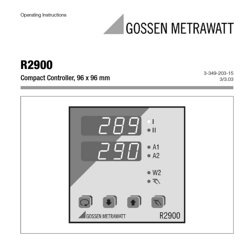
Gossen MetraWatt PROFITEST MF Series User manual

Gossen MetraWatt
Gossen MetraWatt R6000 User manual

Gossen MetraWatt
Gossen MetraWatt R2900 User manual

Gossen MetraWatt
Gossen MetraWatt R2600 User manual

Gossen MetraWatt
Gossen MetraWatt R2080 User manual

Gossen MetraWatt
Gossen MetraWatt SMARTCONTROL ECS User manual

Gossen MetraWatt
Gossen MetraWatt R2700 User manual