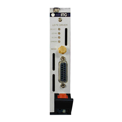
THORLABS ITC8000 User manual

PRO800 / PRO8000 (-4) Series
Modular Combined Laser Current
and Temperature Controllers
ITC8000
Operation Manual
2016

Version:
Date:
Item No.:
3.2
08-Sep-2016
M0009-510-221
Copyright © 2016 Thorlabs

Foreword
Contents 4
1General Information 5
51.1 Safety 61.2 Ordering Codes and Accessories
2Getting Started 7
72.1 Parts List 72.2 Operating Principle 92.3 Operating Elements
3External Connections ITC8xxx 11
123.1 Laser Diode Controller 133.1.1 Connecting the Laser and Monitor Diodes 133.1.2 Connecting Interlock and Status Display 153.2 Temperature Controller 163.2.1 Connecting a Thermistor 163.2.2 Connecting an AD590 163.2.3 Connecting a LM335 163.2.4 Connecting a TEC Element 173.2.5 Polarity Check of the TEC Element 173.2.6 Connecting the Status Display LED
4External Connections ITC8xxxDS15 18
194.1 Connecting the Laser and Monitor Diodes - ITC8000DS15 194.2 Connecting Interlock and Status Display - ITC8000DS15 204.3 Connecting a Thermistor - ITC8000DS15 204.4 Connecting an AD590 - ITC8000DS15 204.5 Connecting a LM335 - ITC8000DS15 214.6 Connecting a TEC Element - ITC8000DS15
5Optimization of Temperature Control 22
225.1 Principle Setup and Function 235.2 PID Adjustment
6Operating Instruction 24
246.1 Pre-Settings 256.2 Functions in the Main Menu 276.3 Functions in the Channel Menu 276.3.1 Display 296.3.2 Changing Parameters 296.3.3 Selecting the Polarity of the Laser and the Monitor Diodes 296.3.4 Calibration of the Monitor Diode 306.3.5 Bias Voltage for the Monitor Diode

306.3.6 Selecting Constant Current or Constant Power Mode 306.3.7 Selecting the Type of the Temperature Sensor 306.3.8 Thermistor Calibration 326.3.9 Temperature Window 326.3.10 Setting the P, I and D Share of the Control Loop 326.4 Switching ON and OFF 346.5 Error Messages
7Communication with a PC 36
367.1 Nomenclature 367.2 Data Format 377.3 Commands and Queries 377.3.1 Select the Module Slot (SLOT) 377.3.2 Query Type of Module (TYPE) 377.3.3 Selecting the Photo Diode Polarity (PDPOL) 377.3.4 Selecting the Operation Mode (MODE) 387.3.5 Programming the BIAS Voltage (VBIAS) 387.3.6 Selecting the Laser Diode Polarity (LDPOL) 397.3.7 Reading the Laser Diode Hardware Limit (LIMCP) 397.3.8 Programming the Laser Diode Software Limit (LIMC) 407.3.9 Setting the Laser Diode Current (ILD) 417.3.10 Setting the Monitor Diode Current (IMD) 427.3.11 Calibrating a Photodiode (CALPD) 427.3.12 Programming the Optical Power (POPT) 437.3.13 Activating the Temperature Protection (TP) 437.3.14 Switching the Laser Output On and Off (LASER) 447.3.15 Reading the Laser Diode Voltage (VLD) 447.3.16 Programming the TEC Current Software Limit (LIMT) 457.3.17 Programming the Temperature (TEMP) 467.3.18 Programming the Temperature Window (TWIN) 467.3.19 Programming the Resistance Window (RWIN) 477.3.20 Selecting the Sensor (SENS) 477.3.21 Programming the Resistance of the Temperature Sensor (RESI) 487.3.22 Thermistor Calibration - Exponential Method 497.3.23 Thermistor Calibration - Steinhart-Hart Method 507.3.24 Programming the PID Shares (SHAREP, SHAREI, SHARED) 507.3.25 Switching the I Share On / Off (INTEG) 517.3.26 Switching the TEC On / Off (TEC) 517.3.27 Reading the TEC Current (ITE) 527.3.28 Reading the TEC Voltage (VTE) 537.4 IEEE Error Messages 557.5 Status Reporting 587.5.1 Standard Event Status Register (ESR)

587.5.2 Standard Event Status Enable Register (ESE) 587.5.3 Status Byte Register (STB) 597.5.4 Service Request Enable Register (SRE) 597.5.5 Reading the STB by Detecting SRQ 597.5.6 Reading the STB by *STB? Command 597.5.7 Reading STB by Serial Poll 597.5.8 Device Error Condition Register (DEC) 607.5.9 Device Error Event Register (DEE) 607.5.10 Device Error Event Enable Register (EDE)
8Maintenance and Service 61
618.1 Troubleshooting
9 Appendix 64
649.1 Technical Data 669.2 Certifications and Compliances 669.3 Literature 679.4 Warranty 689.5 Copyright and Exclusion of Reliability 699.6 Thorlabs 'End of Life' Policy 709.7 List of Acronyms 729.8 Thorlabs Worldwide Contacts

© 2016 Thorlabs
We aim to develop and produce the best solution for your application
in the field of optical measurement technique. To help us to live up to
your expectations and improve our products permanently we need
your ideas and suggestions. Therefore, please let us know about
possible criticism or ideas. We and our international partners are
looking forward to hearing from you.
Thorlabs GmbH
Warning
Sections marked by this symbol explain dangers that might result in
personal injury or death. Always read the associated information
carefully, before performing the indicated procedure.
Please read these advices carefully!
This manual also contains "NOTES" and "HINTS" written in this form.
Attention
Paragraphs preceeded by this symbol explain hazards that could
damage the instrument and the connected equipment or may cause
loss of data.
Note
4

© 2016 Thorlabs
1 General Information
5
1 General Information
The ITC8000 Modules are combined Laser Current and Temperature Controllers that are capable
to control laser diodes and TEC elements (Peltiers) at the same time in order to maintain the
operating parameters of the connected laser diode.
For the PRO8000 mainframe series Thorlabs supplies LabVIEW®- and LabWindows/CVI®-drivers
for Windows 32 bit.
Please refer to http://www.thorlabs.com for latest driver updates.
1.1 Safety
Attention
All statements regarding safety of operation and technical data in this instruction manual will only
applywhenthe unit is operated correctlyas it was designed for.
Prior to applying power to the ITC8000, make sure that the protective conductor of the mains
power cord is correctly connected to the protective earth ground contact of the socket outlet!
Improper grounding cancause electric shock resulting indamage to your healthor evendeath!
Also make sure that your line voltage agrees withthe voltage givenonthe letterplate of the unit and
that the right fuse has beeninserted!
Modules of the ITC8000 Series are allowed to be operated only a mainframe of the PRO8000
series.
To avoid damage to the modules used or to the mainframe, modules must not be installed or
removed whenthe mainframe is switched on.
Allmodules mustbe fixed using the screws provided for this purpose.
The ITC8000 must not be operated inexplosionendangered environments!
Do not remove covers! Do not obstruct the air ventilationslots inthe housing!
Refer servicing to qualified personnel!
Only with written consent from Thorlabs may changes to single components be made or
components not supplied byThorlabs be used.
This precision device is onlyserviceable if properlypacked into the complete original packaging. If
necessary, ask for a replacementpackage prior to return.
Allconnections to the load must be made using shielded cables,unless otherwise stated.
Semiconductor lasers can deliver up to several 100mW of possibly invisible laser radiation!
Improper operation cancause severe eye and healthdamage!
Paystrict attention to the safetyrecommendations of the appropriate laser safetyclass!
Attention
The following statement applies to the products covered in this manual, unless otherwise specified
herein. The statement for other products will appear inthe accompanying documentation.
This equipment has been tested and found to comply with the limits for a Class Adigital device,
pursuantto part15 of the FCC Rules. These limits are designed to provide reasonable protection
against harmful interference when the equipment is operated in a commercial environment. This
equipment generates, uses, and can radiate radio frequency energy and, if not installed and used
in accordance with the instruction manual, may cause harmful interference to radio
communications. Operation of this equipment in a residential area is likely to cause harmful
interference inwhichcase the user will be required to correct the interference at his ownexpense.

© 2016 Thorlabs6
ITC8000
Thorlabs is not responsible for any radio television interference caused by modifications of this
equipment or the substitution or attachment of connecting cables and equipment other than those
specified by Thorlabs. The correction of interference caused by such unauthorized modification,
substitution or attachment will be the responsibilityof the user.
The use of shielded I/O cables is required when connecting this equipment to any and all optional
peripheralor host devices. Failure to do so mayviolate FCC and ICES rules.
Attention
Mobile telephones, cellular phones or other radio transmitters are not to be used withinthe range of
three meters of this unit since the electromagnetic field intensity may then exceed the maximum
allowed disturbance values according to IEC 61326-1.
This product has been tested and found to comply with the limits according to IEC 61326-1 for
using connectioncables shorter than3 meters (9.8 feet).
1.2 Ordering Codes and Accessories
Please refer to the actual catalog or the web for an actual list of available plug in modules and
accessories and for the complete ordering codes.
Ordering Code Short Description
ITC8022 Laser Controller ± 200 mA,
Temperature Controller Module ± 2 A,
9 pinconnector for laser diode, 15 pinconnector for TEC
ITC8022DS15 Laser Controller ± 200 mA,
Temperature Controller Module ± 2 A,
One common15 pinconnector for laser and TEC
ITC8052 Laser Controller ± 500 mA,
Temperature Controller Module ± 2 A,
9 pinconnector for laser diode, 15 pinconnector for TEC
ITC8052DS15 Laser Controller ± 500 mA,
Temperature Controller Module ± 2 A,
One common15 pinconnector for laser and TEC
ITC8102 Laser Controller ± 1 mA,
Temperature Controller Module ± 2 A,
9 pinconnector for laser diode, 15 pinconnector for TEC
ITC8102DS15 Laser Controller ± 1 mA,
Temperature Controller Module ± 2 A,
One common15 pinconnector for laser and TEC
CAB400 Laser Diode Current Controller ConnectionCable for ITC8000 modules, 1.5
m, to connect Thorlabs Laser Diode Mounts
CAB420-15 Temperature Controller ConnectionCable for ITC8000 modules, 1.5 m,to
connect Thorlabs Laser Diode Mounts
CAB430 Laser Diode Current and Temperature Controller ConnectionCable for
ITC8000DS15 modules, 1.5 m, to connect Thorlabs Laser Diode Mounts

© 2016 Thorlabs
2 Getting Started
7
2 Getting Started
2.1 Parts List
Inspect the shipping container for damage.
If the shipping container seems to be damaged, keep it until you have inspected the contents and
youhave inspected the ITC8000 mechanicallyand electrically.
Verifythat youhave received the following items withinthe package:
1. ITC8000 Series Module
2. Operating Manual
2.2 Operating Principle
The ITC8000 modules are bidirectional current sources to control laser diodes that are combined
witha TEC element (Peltier). Different types of temperature sensors are supported. Three types of
modules are available with respect to the maximum laser current, resolution and accuracy (see
Technical Data ).
The ITC8000 modules contain a transimpedance amplifier input for the monitor diode (input
impedance 0 W). Both polarities of the monitor diode are supported. The monitor diode can be
operated either photovoltaic (without bias voltage) or photoconductive, i.e. withbias voltage.
The temperature controller comprises a closed loop amplifier with adjustable settings for P
(proportional), I(integral) and D (differential) share.
Supported temperature sensors
·Standard thermistors (NTC - Negative Temperature CoefficientThermistor) withintwo ranges
- max. 20 kWand max. 200 kW
·IC temperature sensors (AD590, AD592, LM335)
·Pt-100 (RTD - Resistance Temperature Detectors)
Allnecessaryvalue settings are made bythe mainframe operating elements (keypad and rotational
encoder) or via remote control bya computer. The onlyparameter that must be set manually, is the
laser current limit ("absolute hardware limit").
The values for the laser diode current (constant current mode), the monitor diode current (constant
power mode) and the set temperature or set resistance of the ITC8000 modules are set with 16 bit
resolution.
The limit values for the laser diode and TEC current (software limit) as well as for the monitor diode
current(limiting the laser output power) are set witha 12 bit resolution.
The monitor current and the actual temperature (resistance) are read back with16 bit.
The laser diode current, the laser diode voltage, the limit for the laser diode current (hardware
limit),the TEC current and the TEC voltage are read back with15 bit plus sign.
The P, Iand D shares of the analog control loop are set by three independent 12 bit DAC (Digital-
to-Analog Converters)
The built-in mains filter in the mainframe and the careful shielding of the transformer, the micro
processor as wellas the module itself willprovide anexcellentsuppressionof noise and ripple.
64

© 2016 Thorlabs8
ITC8000
Protection Features
To protect the connected laser diode and the TEC element, the ITC8000 modules contain the
following protectioncircuits:
·Soft start when switching on the laser diode current
Protectionfrom capacitive and inductive parasitic elements (switching peaks).
·Software Limits of the laser and TEC current in all operating modes; additional
hardware limit for the laser current.
Protectionfrom destruction.
·Interruption control of the connection cable to the laser diode (interlock)
Protection from accidental operation.
·Contact protection of the laser diode (open circuit)
Protectionfrom cable damage or bad contact.
·Electronic short-circuit switch for the laser diode
Protectionfrom electro-static discharge whentouching the switched-off laser.
·Sensor Protection
Protectionfrom the use of not supported temperature sensors and from interrupted sensor
connection.
·Open-Circuit Protection of the connection cable to the TEC element
Protectionfrom cable damage, bad contact or TEC element withtoo highresistance. When
tripped, a warning is output, but the output remains switched on- the reason is that evena
wrong TEC as still capable to cool the laser diode.
·Separate on and off function for each module
Protectionfrom operating errors.
·Control LED for activated laser and TEC current
Protectionfrom accidental disabling of the temperature control..
·Separate over-temperature protection for each module
Protectionagainst thermal failure of the module.
·Line failure protection
Incase of a line voltage failure the ITC8000 module must be switched onagainmanually.
·Key-operated power switch
Protection against unauthorized or accidental use.
·Action check
After power-up the ITC8000 modules are inLASER OFF mode.

© 2016 Thorlabs
2 Getting Started
9
2.3 Operating Elements
ITC8000 Modules
Operating Elements ITC8000

© 2016 Thorlabs10
ITC8000
ITC8000DS15 Modules
Operating Elements ITC8000DS15

© 2016 Thorlabs
3 External Connections ITC8xxx
11
3 External Connections ITC8xxx
Laser diodes are manufactured inmanydifferent housings. Normally the following components are
installed together inthe housing of the laser:
·Laser diode
·Monitor diode
·TEC element for setting the chip temperature
·Temperature sensor
The laser diode and the TEC element are always sourced against ground by the ITC8000. This is
of a considerable advantage with respect to the protection of the connected devices and to the
current stability.
The modules have a monitor diode input that is set up as a transimpedance amplifier input (input
impedance 0 W). The monitor diode input canbe operated without or withbias voltage (0 V...10 V).
The polarityfor the monitor diode must be set accordingly,see sectionBias Voltage for the Monitor
Diode .
The ITC8000 modules come with separate inputs for laser forward voltage measurement. This
allows a 4-wire connecting scheme that eliminates measurement errors due to the voltage drop
caused bythe injectioncurrent.
The temperature controller sensor input canhandle different types of sensors. A missing sensor or
selectionof a wrong type is detected bythe ITC8000.
30

© 2016 Thorlabs12
ITC8000
3.1 Laser Diode Controller
Pin Assignment of the LD Output Connector
Female 9 pin D-SUB Connector
Pin
Connector
Interlock; Status Display
1
Output Interlock; Status LED - Anode
5
Interlock returnpin; Status LED - Cathode (GND)
Laser Diode
7
LD cathode (withpolarityAG)
8
LD anode (withpolarityCG)
3
LD ground
Monitor Diode
4
Input monitor (photo) diode
2
Ground monitor (photo) diode
Laser Voltage Measurement Input
6
ULD- (cathode)
9
ULD+ (anode)

© 2016 Thorlabs
3 External Connections ITC8xxx
13
3.1.1 Connecting the Laser and Monitor Diodes
We recommend to use separate wires drilled in pairs (twisted pair) in a common shield for laser
diode current, monitor diode current and laser voltage measurement, respectively. The shield must
be connected to ground potential(pin3).
If an external monitor diode is used, it must be connected with a coaxial cable with the outer
conductor to pin2 and the inner conductor to pin4.
Connect laser and monitor diode to the connector jack of the ITC8000 module.
The lines for voltage measurement of the laser diode (pin 6 and pin 9) must be connected as
closelyas possible to the laser diode to avoid measurement errors.
The ground conductor of the monitor diode (pin2) can be connected to the ground conductor of the
laser diode (pin 3). If this is necessary (e.g. laser diodes with integrated monitor diode and
commonground),connect the ground conductors as closelyas possible to the laser diode to avoid
measurement errors whenmeasuring the monitor diode current.
In this case the following pin assignments of the output jack are possible (shown without voltage
measurement):
LD - Laser Diode; PD - Photo (Monitor) Diode
3.1.2 Connecting Interlock and Status Display
Interlock and cable damage monitoring
The interlock function provides a safety feature in order to switch off instantly the laser. Therefore,
the connectionbetweenpin1 and pin5 of the connector jack serves as safetycircuit:
·If the resistance between above mentioned pins is less than 430 W(short circuit allowed), the
laser current is enabled and canbe switched on.
R = 0 to 430 Ω
Note
Using a resistor > 430 Wmay lead to a malfunction as the status of the interlock is then in an
undefined range.
·In the case that the current between the interlock pins is interrupted, the laser controller cannot
be switched on. If this interruption happens during operation, the output will be switched off

© 2016 Thorlabs14
ITC8000
immediately and remains switched off until the interlock circuit is closed again and the laser
current is switched onagain.
Status display
For Laser On/Off status indication, a LED with a 470 Wresistor in parallel can be connected
between the two interlock pins. The LED will light up whenthe laser outputis switched on.
R = 470 Ω
Note
Mispoling the LED may lead to a malfunction as the status of the interlock is then in an undefined
range.

© 2016 Thorlabs
3 External Connections ITC8xxx
15
3.2 Temperature Controller
Pin Assignment of the TEC Output Connector
Female 15 pin D-SUB Connector
Pin
Connector
TEC Element
5, 6
TEC Element +
13, 14, 15
TEC Element - (GND)
Status Display
1
Status LED - Anode
8
Status LED - Cathode (GND)
Temperature Sensor
3
Thermistor - (GND)
4
Thermistor +
10
AD590 - (PT100 for ITC8xxxPT)
11
AD590 + (PT100 for ITC8xxxPT)
Connect the TEC element and the temperature sensor with shielded cables to the TEC connector.
The shielding of the cable mustbe connected to ground (pin13,14,15).

© 2016 Thorlabs16
ITC8000
3.2.1 Connecting a Thermistor
The thermistor is connected betweenpin3 and pin4:
3.2.2 Connecting an AD590
The IC-temperature sensor AD590 is connected betweenpin10 (-) and pin 11 (+).
3.2.3 Connecting a LM335
The IC-temperature sensor LM335 is connected betweenpin10, 11 (+) and pin 8 (-).
3.2.4 Connecting a TEC Element
The TEC element is connected between pins 5, 6 (plus pole) and pins 13, 14, 15 (minus pole).
Connecting a TEC Element
Attention
An reverse poled TEC element may lead to a thermal runaway and destruction of the connected
components. Please refer to sectionPolarityCheck of the TEC Element .
17

© 2016 Thorlabs
3 External Connections ITC8xxx
17
3.2.5 Polarity Check of the TEC Element
Pre-Settings
·Connect TEC element and temperature sensor. The sensor must be ingood thermalcontact
to the active surface of the TEC element.
·Switchonthe PRO8000 (-4) / PRO800 system.
·Select the ITC8000 module.
·Select the correct type of sensor.
·Set the correct value for ITEC, MAX.
Polarity check of the TEC element
Observe TACT (or RACT)and switchonthe module bypressing the key”ON/OFF”
·If TACT (or RACT) runs awayfrom TSET (or RSET), the TEC element is reverse poled. Change
polarityand repeat the procedure.
·If TACT (or RACT) is oscillating around the value TSET (or RSET), the TEC element is connected
correctly, but the P, Iand D share values of the control loop are still incorrect. (Refer to
sectionPID Ajustment )
·If TACT (or RACT) is settling properlyto the value TSET (or RSET), the TEC element has been
connected correctly, the values for the P-,I- and D-share ofthe control loop maystill need
improvement.
3.2.6 Connecting the Status Display LED
To display the operating status of the temperature controller, a standard LED may be used
between pin1 and pin8. The LED will light up whenthe current output is switched on.
Note Not for ITC8000DS15!
23

© 2016 Thorlabs18
ITC8000
4 External Connections ITC8xxxDS15
The ITC8000DS15 Combined Controllers come witha single output connector that accommodates
the external connections for boththe laser current and the temperature controllers. The functionality
is the same, except for the TEC controller status LED. Therefore, in this section are stated the
external connections of the common 15 pin output connector with respect to the different pin
assignment.
Pin Assignment of the Common LD/TEC Output Connector
Female 15 pin D-SUB Connector
Pin
Connector
TEC Element
7
TEC Element +
8
TEC Element - (GND)
Temperature Sensor
14
Thermistor - (GND)
15
Thermistor +
13
AD590 -
6
AD590 +
Laser Diode
10
LD cathode (withpolarityAG)
11
LD anode (withpolarityCG)
3
LD ground
Monitor Diode
4
Monitor (photo) diode anode (or cathode withbias)
2
Monitor (photo) diode ground
Laser Voltage Measurement Input
9
ULD- (cathode)
12
ULD+ (anode)
Interlock; Status Display
1
Output Interlock; Status LED - Anode
5
Interlock returnpin; Status LED - Cathode (GND)
This manual suits for next models
3
Table of contents
Other THORLABS Temperature Controllers manuals
THORLABS
THORLABS TED350 User manual

THORLABS
THORLABS TXP Series User manual

THORLABS
THORLABS MTD415T User manual

THORLABS
THORLABS T-Cube TTC001 User manual

THORLABS
THORLABS TC300 User manual

THORLABS
THORLABS TED4015 User manual

THORLABS
THORLABS TED200C User manual
THORLABS
THORLABS Blueline Series User manual
THORLABS
THORLABS TC200 User manual

THORLABS
THORLABS TCLDM9 User manual