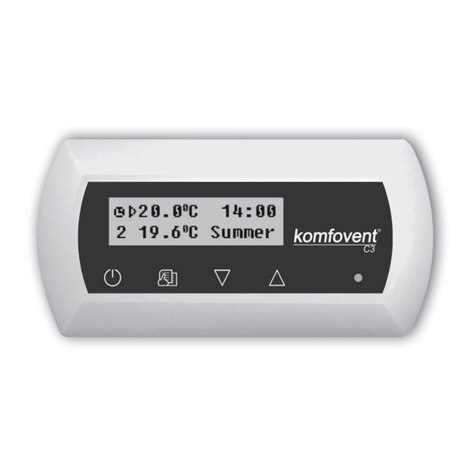
Komfovent C5.1 User manual

C5.1
EN Electrical installation and Operation Manual


UAB KOMFOVENT we reserve the right to make changes without prior notice
C5.1_22- 08 3
Thissymbolindicatesthatthisproductisnottobedisposedofwithyourhouseholdwaste,accordingtothe
WEEEDirective(2002/96/EC)andyournationallaw.Thisproductshouldbehandedovertoadesignated
collection point, or to an authorised collection site for recycling waste electrical and electronic equi-
pment (EEE). Improper handling of this type of waste could have a possible negative impact on the
environment and human health due to potentially hazardous substances that are generally associ-
ated with EEE. At the same time, your cooperation in the correct disposal of this product will contri-
bute to the eective usage of natural resources. For more information about where you can drop o
your waste equipment for recycling, please contact your local city oce, waste authority, approved
WEEE scheme or your household waste disposal service.
Content
1. ELECTRICAL INSTALLATION MANUAL......................................................................................................................4
1.1. Air Handling Units Sections Connection.................................................................................................................4
1.2. Electric Power Supply Connection ...........................................................................................................................4
1.3. External Elements Connection...................................................................................................................................5
1.4. Temperature Sensors Installation..............................................................................................................................6
1.5. Requirements for the installation of the control panel ....................................................................................6
1.6. Control panel connection ............................................................................................................................................6
2. OPERATION MANUAL ........................................................................................................................................................7
2.1. Unit Control........................................................................................................................................................................7
2.2. Control panel indication...............................................................................................................................................7
2.3. Parameters overview .....................................................................................................................................................8
2.4. Operation modes selection.........................................................................................................................................8
2.5. Menu ....................................................................................................................................................................................9
2.5.1. Overview.................................................................................................................................................................9
2.5.1.1. Alarms........................................................................................................................................................9
2.5.1.2. Operation counters .............................................................................................................................9
2.5.1.3. Eciency status....................................................................................................................................9
2.5.1.4. Detailed information ..........................................................................................................................9
2.5.2. Functions..............................................................................................................................................................10
2.5.2.1. Air quality control ..............................................................................................................................10
2.5.2.2. Operation on demand ....................................................................................................................10
2.5.2.3. Outdoor compensated ventilation ............................................................................................11
2.5.2.4. Summer night cooling ....................................................................................................................11
2.5.2.5. Minimum temperature control ...................................................................................................11
2.5.2.6. Override function .............................................................................................................................12
2.5.2.7. Humidity control ...............................................................................................................................12
2.5.3. Scheduling...........................................................................................................................................................13
2.5.3.1. Operation program...........................................................................................................................13
2.5.4. Settings .................................................................................................................................................................13
2.5.3.2. Holidays.................................................................................................................................................13
2.5.4.1. Air handling unit settings ..............................................................................................................14
2.5.4.2. Personalization...................................................................................................................................16
2.6. Control of air handling units through a web browser.....................................................................................16
2.7. Additional control options.........................................................................................................................................17
2.7.1. Combined water coil control .........................................................................................................................17
2.7.2. Inverter direct evaporation cooler control ..............................................................................................17
2.7.3. Multi-level control of direct evaporation cooler ...................................................................................17
2.7.4. Reversal of direct evaporation coolers......................................................................................................17
2.8. Troubleshooting ............................................................................................................................................................18

EN
UAB KOMFOVENT we reserve the right to make changes without prior notice
C5.1_22- 08
4
1. ELECTRICAL INSTALLATION MANUAL
Installation works can be performed only by the specialists that have required qualication. During
installation following requirements must be fullled.
It is recommended to lay control cables separately from power cables, or use
shielded cables. In such case it is necessary to earth cable shielding!
If AHU is used outdoors, all cables and wires, that are routed outside of the unit
must be additionally protected from UV damage; for example it can be mounted
inside of cable tray, corrugated tube or similar.
1.1. Air Handling Units Sections Connection
Afterunitpartshavebeenconnectedtogether(seeunitinstallationinstruction),unitsectionsconnecting
cables and wires are connected.
Connector connection is performed strictly according to numeration given in wir-
ing diagram, or adequate markings (see unit electric scheme).
When disconnecting unit sections, do not pull by connecting wires and cables!
1.2. Electric Power Supply Connection
If the air handling unit voltage is ~230 V; 50 Hz it is necessary to install the socket with grounding of
corresponding capacity (see electric diagram unit). If the voltage is ~400 V; 50 Hz, the cable of electrical
power supply is connected to the main switch, which is located on the unit’s outside wall. It is necessary
to connect earthing! Electrical power supply connection and other cable thicknesses are specied in the
wiring diagram.
Air handling units designed for 400 V AC supply voltage must be connected to
the stationary installation by solid cable. It is recommended to connect AHU to
the mains via automatic circuit breaker with 300 mA current leakage protection
(type B or B+).
Before connecting unit to the electrical power supply, it is necessary to check
whether earthing has been installed properly.

UAB KOMFOVENT we reserve the right to make changes without prior notice
C5.1_22- 08 5
1.3. External Elements Connection
The air handling unit is designed with external connection terminals which are located on the con-
troller box, inside the air handling unit. All external control elements are connected to the terminals.
1
2
1. „Ethernet“ computer network or internet connection
2. Control panel connection
1.3 a Picture. Controller with connection terminals
Total power of all external elements with 24V supply may not exceed 15W.
37 38 39 40 41 42 43 44 45 46 47 48
13 14 15 16 17 18 19 20 21 22
~24V
~24V
~24V
GND
0..10V
0..10V
0..10V
NO
NO
NO
NO
NO
C
C
FG1
DX
Indication
control
Cold water
mixing valve /
DX capacity control
Hot water
Cooling water
Heating water
pump
230V AC, 1A
pump 230V AC, 1A
mixing valve
actuator
Humidifier
Run
Alarm
Common
Common
TG3 TG2 TG1 S1S2
IN5 L
L
N
N
N
N
N
23 24
25 26 27 28 29 30 31 32 33 34 35 36
~24V
~24V
~24V
~24V
0..10V
0..10V
0..10V
0..10V
C
NTC
B5
B9 B8 B7 B6
MODBUS
RS485
connection
OVR control
Common
Return water
Supply air
temperature sensor
temperature sensor
Fire system
External stop
Control input
External control
B1
NTC
A
GND
IN4
IN3
IN2
IN1
B
N
N
N
N
12345678910 11 12
Water pump /
coil alarm
C
DX3 / Heating
DX2 / Cooling
DX1/ Start
Air damper
actuator
Supply air
pressure sensor
Exhaust air
pressure sensor
Air quality sensor
Humidity sensor
1.3 b Picture. External control elements connection

EN
UAB KOMFOVENT we reserve the right to make changes without prior notice
C5.1_22- 08
6
1.4. Temperature Sensors Installation
The supply air temperature sensor B1 (1.4 a Picture) is mounted in the air duct in a projected place for it;
after cooler section (if provided). The minimal distance from the duct connection of the unit up to the sensor
should be not less than double diameter of the circular connection or a diagonal of rectangular connection.
The water temperature sensor B5 (1.4 b Picture) is mounted on the water pipe by screwing it into the
provided hole. The sensor must be thermo insulated!
Supply air temperature sensor B1 Water temperature sensor B5
1.4 a Picture 1.4 b Picture
B
D
≥ 2D
+–
B1
1.5. Requirements for the installation of the control panel
1. The control console should be installed in a room where the following conditions are ensured:
1.1. ambient temperature: 0 ºC ... 40 ºC;
1.2. relative humidity range: 20 % ... 80 %;
1.3. protection against dripping of water (IP X0).
2. Control panel connection is provided through a hole in the back or bottom side.
3. The panel can be mounted on a ush mounting box or in any other place just screwing two holes on
the fastening surface.
Do not use any other type or size screws but those that are packed together for
control panel mounting. Wrong screws may damage electronics board.
1.6. Control panel connection
The control panel is connected to the controller box (see Picture 1.3 a). The length of the cable for
connecting the panel with the unit may not exceed 150 m.
Yellow (A) () White
(+) RedGreen (B)
Yellow(A)
(+)Red
Green(B)
()White Yellow (A) () White
(+) RedGreen (B)
Yellow(A)
(+)Red
Green(B)
()White
1.6 Picture. Control panel connection
Control panel connection and other cable thicknesses are specied in the wiring
diagram!
Remove protective screen tape, before mounting front cover on the control panel!

UAB KOMFOVENT we reserve the right to make changes without prior notice
C5.1_22- 08 7
2.1 Picture. Control panel
2. OPERATION MANUAL
2.1. Unit Control
Air handling units control system ensures control of the physical
processes that are taking place inside the air handling unit.
Control system consists of:
• main controller module;
• circuit breakers and main switch;
• control panel1, which can be installed in the convenient place for
the user;
• pressure and temperature sensors.
Control panel (2.1 Picture) is designed for remote air handling unit
control, setting and display of controller parameters.
2.2. Control panel indication
ECONOMY 1
21,9 °C
21,3 °C
Temperature
16:30
Selection of
operation
modes
Menu
Indication of unit
operation modes and
functions
Main parameters
overview window
Switching between
overview windows
Time
Explanation of the displayed symbols
Air humidier
operation
Summer night cooling
mode
Weekly operation
mode
Holiday operation
mode
„Override“ mode
Alarm signal
Fan operation
Air ow increasing
by activated function
(see chapter Functions)
Air ow decreasing
by activated function
(see chapter Functions)
Energy recovery operation
Air heater operation
Air cooler operation
Supply air temperature
Extract air temperature
Supply air volume
Extract air volume
Supply air humidity
Extract air humidity
Extract (room)
air quality
1 Sold separately.

EN
UAB KOMFOVENT we reserve the right to make changes without prior notice
C5.1_22- 08
8
2.3. Parameters overview
The main parameters of the unit are indicated in four main windows of the panel: temperatures
indication, air ow, air quality (humidity) and energy saving.
All other unit parameters are presented in the menu “Overview” (see 9 page).
ECONOMY 1
16:30
90%
18 kW
Energy saving
ECONOMY 1
60% RH
800 ppm
Air quality
16:30
ECONOMY 1
12500 m3/h
13100 m3/h
Air ow
16:30
ECONOMY 1
21,9 °C
21,3 °C
Temperature
16:30
2.4. Operation modes selection
Six operation modes are possible, one of them user can select directly from control panel main
window:
• Two Comfort and two Economy modes, for each of them the user can set air ow and temperature.
• Special mode allows the user not only to set air ow and temperature, but also to select blocking or
using heating, cooling and other functions.
• OFF mode completely turns o the unit.
Reset settings
ECONOMY 1
Supply air ow
1250 m3/h
Extract air ow
1250 m3/h
Setpoint
20 °C
Operation modes
COMFORT 1
COMFORT 2
ECONOMY 1
ECONOMY 1
SPECIAL
OFF
ECONOMY 1
21,9 °C
21,3 °C
Temperature
16:30
When AHU is stopped, by pressing modes button, it is possible to start the unit on the last active
ventilation mode.
When starting CF type AHU for the rst time, it will be needed to perform heat exchanger calibra-
tion, which is used for frost prevention function (See 2.5.1.3).
Temperature
ON?
OFF
Temperature
Start CF exchanger
calibration?
STARTING

UAB KOMFOVENT we reserve the right to make changes without prior notice
C5.1_22- 08 9
2.5. Menu
Menu of panel consists of the four points:
Functions Settings
Overview Scheduling
Menu
ECONOMY 1
21,9 °C
21,3 °C
Temperature
16:30
Alarms
Operation counters
Eciency status
Detailed information
Overview
2.5.1. Overview
Main air handling unit parameters are presented
in the main windows (Chapter 2.3). All other informa-
tion, relating to the operation of the unit, malfunctions
and eciency status is detailed in overview menu.
2.5.1.1. Alarms
This menu displays the notication of existing
faults.
After failure elimination (see chapter 2.8), mes-
sages are deleted by selecting “Delete”. By clicking on
„History“ can be viewed up to 50 registered alarms.
2.5.1.2. Operation counters
This menu displays operation time of the fans, the
consumed energy of the heater and how much energy
was recovered by the heat exchanger.
2.5.1.3. Eciency status
Menu for the heat exchanger eciency and en-
ergy recovery monitoring in real time.
Also in this menu it is possible to start CF exchang-
er calibration1, if it was not performed during rst start
of AHU. If calibration was successful and “Calibrated”
is shown – there is no need to start calibration again.
During calibration AHU will operate for about 10 min-
utes on dierent ventilation intensities while measur-
ing internal pressure. Thus do not open AHU doors, do
not regulate duct system and do not change any set-
tings during CF calibration. If you wish to stop calibra-
tion – turn o the unit from the control panel.
2.5.1.4. Detailed information
All temperature sensor readings, functioning of
separate air handling unit elements and other de-
tailed information is available in this menu.
1 Only in CF units.
Functions Settings
Overview Scheduling
Menu
Operation counters
Air heater
121 kWh
Supply fan
873 h
Exhaust fan
875 h
Recovered energy
1440 kWh
21A
Electric heater overheating
3B
VAV calibration fail
Alarms
Delete History
Detailed information
Supply air ow
350 m3/h
1 / 3
Supply air temperature
21,9 °C
Extract air temperature
22,1 °C
Outdoor air temperature
16,6 °C
Water temperature
25,3 °C
Calibrated
CF exchanger calibration
Efficiency status
83%
Energy saving
90%
Energy recovery
4,1 kW
Heat exchanger efficiency

EN
UAB KOMFOVENT we reserve the right to make changes without prior notice
C5.1_22- 08
10
2.5.2. Functions
In this menu item, the user can activate and set
additional unit functions.
blank box: function is not activated
gray box: function is activated, but currently not opera-
ting
blue box: currently operating function
2.5.2.1. Air quality control
Air quality control is designed according to:
• CO2sensor1[0...2000 ppm];
• air quality sensor VOCq [0...100 %];
• air pollution sensor VOCp [0...100 %];
• relative humidity sensor [0...100 %];
• temperature sensor [0...50 ºC].
Depending on the type of the selected sensor, the value of the air quality
function to be maintained is set, and the air handling unit intensity will be ad-
justed according to that value. Ventilation intensity will be increased automati-
cally in the case of deviation from the set value and decreased again when it
is approached. For example, if the unit is designed with the CO2maintenance
function and is equipped with a CO2sensor, after setting value 800 ppm, this set
CO2level will be maintained by adjusting ventilation intensity, i.e. ventilation intensity will be increased if
the CO2level grows and will be decreased when it returns to the previous condition.
The function of air quality operates only if no other below function is active at the
same time:
• summer night cooling;
• min. temperature control;
• outdoor compensated ventilation.
2.5.2.2. Operation on demand
The air handling unit start-up function is designed to start the unit which
currently o, when one of the selected parameters has exceeded the critical
limit.
The function provided for the start-up of the unit according to:
• room CO2sensor;
• room air quality sensor VOCq;
• room air pollution sensor VOCp;
• room relative humidity sensor;
• room temperature sensor.
Operation on demand (start-up / shut-down) is performed by the
same sensor which is used in the control of the “Air quality func-
tion”.
A room sensor with the analogue output (0...10 V DC) should be
designed for this function.
1 Factory setting.
Functions
1 / 2
Air quality
control
Operation on
demand
Outdoor compen-
sated ventilation
Summer night
cooling
Minimum tempera-
ture control
Functions Settings
Overview Scheduling
Menu
Reset settings
Enable
Setpoint 1
1000 ppm
Setpoint 2
880 ppm
Mode 1
COMFORT 1
Mode 2
COMFORT 2
Air quality control
Reset settings
Enable
Setpoint
1000 ppm
Operation on demand

UAB KOMFOVENT we reserve the right to make changes without prior notice
C5.1_22- 08 11
2.5.2.3. Outdoor compensated ventilation
The ventilation compensation function adjusts the air volume depending
on the existing outdoor temperature. It is possible to enter four temperature
points, with two of them dening winter conditions and the other two dening
summer conditions. When compensation start and end points for both winter
and summer seasons are entered (it is also possible to enter only one of them,
example only winter compensation; in this case, the start and the end points of
summer compensation should be the same), the current ventilation intensity
will be decreased in proportion according to the outdoor temperature until it
reaches the minimum possible ventilation level of 20 %.
The ventilation compensation function does not operate when
summer night cooling function is active.
F1 – user-selected air ow (actual)
F2 – minimum air ow 20 %
W1 – winter compensation start point
W2 – winter compensation end point
S1 – summer compensation start point
S2 – summer compensation end point
Outdoor
temperature,
C
Ventilation
intensity,
%
2.5.2.4. Summer night cooling
Summer night cooling function is intended for energy saving during the
summer season: by utilizing the outside chill of night hours, it is possible to
cool down heated rooms, i.e. to remove excessive heat that accumulated in the
room during day hours.
Summer night cooling function can start at night (from 00:00 h to 06:00
h a.m.) at any time, even when the air handling unit is not working and is in
standby mode. User can set indoor temperature, at which this function starts
and stops.
When this function is active, the current ventilation level is switched to the
maximum ventilation intensity (100 %) and ventilation is performed only by
means of fans, i.e. at that time neither the air cooling nor the energy recovery
functions operate.
Summer night cooling function has an operating priority over the following func-
tions: outdoor compensated ventilation and the air quality function.
2.5.2.5. Minimum temperature control
In winter time the minimum temperature control function forcibly reduces
the supply and extract air ow set by the user when the heater capacity avail-
able in the unit is insucient and/or heat recovery does not ensure minimally
possible temperature supply to the room. The user can set a separate supply
air temperature value so that when that value is not achieved, the intensity
of the ventilation unit starts to be reduced automatically. The air ow may be
reduced to the minimally possible ventilation intensity of 20 %.
During the summer, when the air handling unit provided with cooler, this
function according to the same user-set value limits the cooling capacity, thus
ensuring the minimum possible temperature supply to the room.
In ventilation intensity control, this function has top priority over
“Outdoor compensated ventilation” and “VAV” functions.
Reset settings
Enable
Winter stop
-15 °C
Summer start
25 °C
Winter start
5 °C
Summer stop
35 °C
Outdoor compensated ...
Reset settings
Enable
Start when indoor
25 °C
Stop when indoor
20 °C
Summer night cooling
Reset settings
Enable
Setpoint
15 °C
Minimum temperature ...

EN
UAB KOMFOVENT we reserve the right to make changes without prior notice
C5.1_22- 08
12
2.5.2.6. Override function
Override (OVR) control of the unit can be performed by the external con-
tact (see Picture 1.3 b) or device (timer, switch, thermostat, etc.). The received
signal from the outside activates the OVR function, which ignores the current
operation modes of the unit and performs one of the selected actions listed
below:
• switches o the air handling unit;
• switches over the unit to operation according to the mode “Comfort1”;
• switches over the unit to operation according to the mode “Comfort2”;
• switches over the unit to operation according to the mode “Economy1”;
• switches over the unit to operation according to the mode “Economy2”;
• switches over the unit to operation according to the mode “Special”;
• switches over the unit to operation according to the weekly schedule.
The OVR function provides for three operation modes selectable depending on the needs of the
user:
1. The mode “When on” – the function will respond to the external control contact only when the air
handling unit is on.
2. The mode “When o” – the function will respond to the external control contact only when the air
handling unit is o.
3. The mode “Always” – the function will respond to the external control contact irrespective of the
operating condition of the unit.
The OVR function has the top priority and, therefore, ignores all previous modes.
The function remains active as long as the external control contact is in the closed
position.
2.5.2.7. Humidity control
Humidity control function is designed for maintenance of air humidity de-
termined by the user. For proper operation of the function one or two addi-
tional humidity sensors shall be connected, depending on where humidity will
be maintained. There are two modes for maintenance of humidity:
• Supply air. The determined humidity of supply air is maintained, using the
supply air duct humidity sensor (B9).
• Room air. The determined humidity of indoor air is maintained, using the
room air or exhaust air duct humidity sensor (B8). The supply air humidity
limit is set using the duct humidity sensor or hydrostat (B9).
One of the below methods can be chosen for maintenance of the deter-
mined humidity:
• Humidication of air. There is a control signal of 0...10 V, directly reecting the capacity of the hu-
midier from 0 to 100 %. If humidication is required, the control is transferred through the output
TG3 of the controller.
• Dehumidication of air. There is a control signal of 0...10 V, directly reecting the capacity of the
dehumidier from 0 to 100 %. If dehumidication is required, the control is transferred through the
output TG3 of the controller.
• Dehumidication of air: cooling-heating. Dehumidication is performed using the coolers and
heaters available in the air handling unit. If there are several coolers and heaters, then it shall be pre-
-determined which of them will be used in the dehumidication process.
• Humidication and dehumidication of air. For humidication of air the control signal of 0...10 V
is used through the output TG3 of the controller, and the dehumidication of air is performed using
the coolers and heaters available in the unit.
Reset settings
Enable
Override
If on
Mode
ECONOMY 1
Override function
Reset settings
Enable
Setpoint 1
55% RH
Mode 1
COMFORT 1
Setpoint 2
30% RH
Mode 2
ECONOMY 2
Humidity control

UAB KOMFOVENT we reserve the right to make changes without prior notice
C5.1_22- 08 13
2.5.3. Scheduling
Menu for planning of the air handling unit op-
eration according to the weekly program and the
annual calendar.
Scheduling
Operation program
Holidays
Functions Settings
Overview Scheduling
Menu
2.5.3.1. Operation program
User can set up to twenty operation programs
for the unit. For each program possible to adjust
the mode of operation, day of the week and the
time interval.
Program 2
Operation mode
COMFORT 1
Weekdays
Mo/Tu/We/Th/Fr/Sa/Su
Start time
00:00
Stop time
24:00
Delete program
Add new program
Enable
Program 1
Operation program
2.5.3.2. Holidays
Holiday schedule species the time period
during which the unit operates under selected
mode. Possible to set up to ten holidays.
Holidays 2
Operation mode
STANDBY
From
12/14
Till
12/26
Delete holiday
Holidays
Holidays 1
Add new holiday
2.5.4. Settings
This menu is for air handling unit and the user
parameter setting.
Air handling unit
Personalization
Settings
Functions Settings
Overview Scheduling
Menu
If the maintenance of the room air humidity is provided for, then the humidity
function will prevail over the air quality and recirculation functions, i.e. when hu-
midication or dehumidication is required, these functions will be blocked.
Humidity control function must be ordered in advance.

EN
UAB KOMFOVENT we reserve the right to make changes without prior notice
C5.1_22- 08
14
2.5.4.1. Air handling unit settings
Temperature control
The air handling unit provides for several tem-
perature control modes:
• Supply. The unit supplies air according to the
temperature preset by the user.
• Extract. Unit automatically supplies air of such
temperature to maintain preset exhaust air
temperature.
• Room. Operation is similar to the mode “ex-
haust” but temperature is maintained by the
sensor mounted in the room (B8).
• Balance. Supply air temperature maintenance value will be determined automatically from the exist-
ing exhaust air temperature, i. e., what temperature air will be removed from the premises, the same
temperature air will be supplied back.
When “Balance” is selected, the temperature setpoint disappears.
Air volume control
Supply and exhaust air volumes control modes have been provided in the unit:
• CAV – constant air volume control mode. The unit will supply and extract a constant air ow which
is preset by the user, irrespective of any changes occurring in the ventilation system;
• VAV – variable air volume control mode. The unit will supply and extract an air ow with regard to
the ventilation needs in dierent rooms. In case of frequently changing ventilation demands this air
volumes maintenance mode signally reduces unit exploitation costs.
It is possible to use a simplied VAV control function, “single-ow VAV control”. It means that the
performance of this function requires only a single air ow pressure sensor, which is installed in
a variable air duct system (e.g. in supply air). This variable system is called the master ventilation
system, according to which control is performed, while the other air ow (in this case, discharged
air) operates as the slave ventilation system and always follows the master one. If the supply air re-
quirement in the ventilation system which is assigned as the master system decreases, the intensity
of discharged air in the slave system is reduced correspondingly by the same percentage.
If the variable air volume control function is mode is selected, the initial calibration
of the control mode must be performed; otherwise, the unit will not operate if the
VAV mode is selected.
Variable air volume control mode calibration:
1. Before start of calibration the air distribution and exhaust devices in ventilation system should be
adjusted, all valves for variable air ow in a way enabling air supply to all ventilated premises should
be opened.
2. After switch on of the unit the VAV mode should be selected and calibration procedure should be
conrmed. After the end of the calibration, depending on the conguration of pressure sensors, VAV
mode status will change to Supply, Extract, Double.
3. After calibration the air handling unit further will operate in the previous mode.
• DCV– direct controlled volume. The air handling unit will operate similarly as in the CAV mode, but
air volumes will be maintained directly in accordance with the values of the B6 and B7 analog input
signals of controller. After giving the signal 0... 10 V to the appropriate input, it will be converted
according to the current determined air volume. For example, if the maximum air ow of the unit is
1000 m3/h, setpoint in the panel – 800 m3/h, and the B6 input value – 7 V, the unit will supply constant
air volume of 560 m3/h, i.e., 70% of the set value. The same applies to the exhaust air only by B7 input.
Air handling unit
Temperature control
Flow control
Air quality
Time/Date
Connectivity
1 / 2
Reset settings
Air handling unit
Panel sensor calibration
2 / 2

UAB KOMFOVENT we reserve the right to make changes without prior notice
C5.1_22- 08 15
Air quality
Selected air quality sensor type is used in AQC, OOD functions.
Sensor type
CO2
VOCq
VOCp
RH
TMP
Time / Date
Time and date is required for air handling unit
operation planning.
Also it is possible to activate automatic daylight
saving time.
Connectivity
• IP address and subnet mask. Setting is required
when air handling unit is connected to PC ne-
twork or Internet.
• Controller ID. Number that identies the cont-
roller, when several air handling units are connected to common network and controlled by one
control panel.
• RS-485. Settings of external RS-485 interface (1, 2, 3 terminals, picture 1.3 b).
Panel sensor calibration
If the temperature and/or relative humidity measured by internal control panel sensors do not
match the parameters measured by other devices, the accuracy of the sensors can be adjusted in this
menu. The measured temperature may be adjusted within ± 5 ° C and the humidity within ± 10% range.
Temperature correction
0,0 °C
Humidity correction
0,0%RH
Panel sensor calibration Panel sensor calibration
Temperature correct...
0,0°C
-5,0 °C
5,0 °C
Panel sensor calibration
Humidity correction
0,0
%RH
-10,0%RH
10,0%RH
Enable
Daylight saving time
Time/Date
Time
09:40
Day/Month
25/05
Year
2019
Daylight saving time
On

EN
UAB KOMFOVENT we reserve the right to make changes without prior notice
C5.1_22- 08
16
2.5.4.2. Personalization
In this item for the user are presented menu language, measurement units
and other control panel settings.
2.6. Control of air handling units through a web browser
You may not only monitor the operation of air handling units and the func-
tionality of their individual components, change settings and activate extra
functions by means of control panel but also by your computer. All you need is
to connect the unit to the computer, local area network or the Internet using
a network cable.
Standard CAT 5 network cable
How to connect the unit directly to your computer:
1. Plug one end of the network cable into the controller port on the unit (see Picture 1.3 a) and the
other end to the computer.
2. Go to the properties of your network card and enter IP address, e.g. 192.168.0.200, and subnet mask
255.255.0.0.
3. Open the web browser on your computer and disable all proxy servers in the settings.
4. In the address bar of your web browser enter the IP address associated with the air handling unit;
the default IP address is 192.168.0.50. You can change it at any time on the control panel or from web
browser (see connection settings).
Note: It is recommended to download the latest version of your web browser before use.
5. If the connection is successful, a window prompting to enter your user name and password appears:
Note: the user name is “user”. The default password is also “user”; after logging in, the user can later change the password
to any other of his/her choice (see user interface settings).
If the user has forgotten the modied password, it can be set to the default. To do
this, user should to restore the factory settings of the air handling unit.
Personalization
Language
English
Flow units
m3/h
Screen saver
On
Panel lock
O
Touch sound
Click

UAB KOMFOVENT we reserve the right to make changes without prior notice
C5.1_22- 08 17
2.7. Additional control options
2.7.1. Combined water coil control
For the air handling unit with the combined water coil (Combi-coil – heater and cooler in one) the
control of the mixing valve actuator is provided both under the air heating and cooling modes. The
actuator is connected to the control terminals of the heating circuit and operates only under the heat-
ing mode by default. However upon transfer of the feedback signal conrming that there is cold water
within the circulation system to the control terminals (IN4) of the external control (e. g., by connecting
additional device: thermostat, switch, etc.), the air cooling function will be activated, and the mixing
valve actuator (TG1) will be controlled under the air cooling mode.
2.7.2. Inverter direct evaporation cooler control
By default all units are provided with inverter type DX cooler control, which allows stepless control
of the compressor. For the inverter unit power control, there is a modulated signal (TG2), as well as sig-
nals: cooler start (DX1), cooling demand DX2, heating demand DX3 (see Pic. 1.3 b).
There are three dierent control methods:
1. Universal control, suitable for most cooler units1.
2. Control adapted to Panasonic cooler units.
3. Control adapted to Daikin cooler units.
2.7.3. Multi-level control of direct evaporation cooler
For air cooling in the air handling unit there is provided 3 control contacts (connection is shown in
Picture 1.3 b). Depending on how much will be cooling steps and how it will be divided on steps, it is rec-
ommended to select theoptimal control method. If the capacity of all steps is the same, then only three
control steps are possible. If cooling capacities of steps are close to ratio 1-2-4 (the capacity of each of
the following steps is double the previous), then cooler control will be realized with seven cooling steps.
Example: To the terminals DX1 is connected 1kW cooler, to DX2 – 2kW and to terminals DX3 con-
nected cooler with 4kW capacity. Control will be in steps:
1: 1 kW; 2: 2 kW; 3: 1 kW + 2 kW; 4: 4 kW; 5: 1 kW + 4 kW; 6: 2 kW + 4 kW; 7: 1 kW + 2 kW + 4 kW.
The function of step rotation is provided, when capacities of coolers are the same.
The number of direct evaporation cooling units must be provided in advance.
2.7.4. Reversal of direct evaporation coolers
There is a reverse option of direct evaporation coolers, i.e. when the cooler is switched to the heat-
ing mode. In such case, there must be only max 3 cooling control steps. There are control terminals DX3
for connection of the cooler reversing signal “Heating” (Pic. 1.3 b.).
The option of reversal of direct evaporation cooling units must be provided in ad-
vance.
1 Factory setting.

EN
UAB KOMFOVENT we reserve the right to make changes without prior notice
C5.1_22- 08
18
2.8. Troubleshooting
If the unit fails to operate:
• Make sure that the unit is connected to the power supply network.
• Check whether the main switch (if designed) is turned on.
• Check all fuses of the automatics. If necessary, replace blown-out fuses with new ones having the
same electrical parameters (the sizes of the fuses are indicated on the schematic electrical diagram).
• Check whether there is any failure message on the control panel. If there is indication, it needs to be
eliminated rst. In order to eliminate the failure, follow the table.
• If nothing is indicated on the control panel, check whether cable connecting control panel with the
unit is not damaged.
2.8 Table. Alarms indicated on the control panel, their possible causes and elimination methods
Code Message Possible cause Elimination
14B Service time
If unit continuous operation
(without breaks) was 12 months,
then periodic inspection message
appears.
After disconnecting the unit from
power supply, it is necessary to
carry out periodic inspection of
the unit, i.e. to check the condition
of the heat exchanger, the heater
and fans.
1B, 19A Low supply air ow Too high resistance of the ventila-
tion system.
Check pressure pipes, air dampers,
air lters and make sure that the
ventilation system is not blocked.
2B, 20A Low extract air ow Too high resistance of the ventila-
tion system.
Check pressure pipes, air dampers,
air lters and make sure that the
ventilation system is not blocked.
3B VAV calibration fail Pressure sensors are not con-
nected or broken.
Check connections of the sensor or
replace the sensor.
4B Change outdoor air
lter The fresh air lter is blocked. Shut down the unit and replace
the lter.
5B Change extract air
lter The extract air lter is blocked. Shut down the unit and replace
the lter.
6B -11B Electric heater o The heater is disconnected due to
too low air volume.
As soon as the heater cools down,
protection resets automatically. It
is recommended to increase the
ventilation intensity level.
113B,114B CF exchanger not
calibrated
CF exchanger calibration not
performed or failed
Make sure that all doors are
closed, there is no obstruc-
tions in the ducts and AHU can
reached airflow setpoint of COM-
FORT 1 mode. Repeat calibration
manually (see2.5.1.3.).
127B Service mode Temporary mode, which can be
activated by the service personnel.
The service mode is switched
o by simply deleting the alert
message.
1A, 2A Supply air tempera-
ture sensor failure
The supply air temperature sensor
is not connected or broken.
Check connections of the sensor or
replace the sensor.
3A, 4A Extract air tempera-
ture sensor failure
The discharged air temperature
sensor is not connected or broken.
Check connections of the sensor or
replace the sensor.

UAB KOMFOVENT we reserve the right to make changes without prior notice
C5.1_22- 08 19
Code Message Possible cause Elimination
5A, 6A Outdoor air tempera-
ture sensor failure
The external air temperature sen-
sor is not connected or broken.
Check connections of the sensor or
replace the sensor.
7A, 8A Exhaust air tempera-
ture sensor failure
The exhaust air temperature sen-
sor is not connected or blocked.
Check connections of the sensor or
replace the sensor.
9A, 10A Water temperature
sensor failure
The water temperature sensor is
not connected or broken.
Check connections of the sensor or
replace the sensor.
11A Return water tem-
perature low
Return water temperature of the
heater dropped below the permis-
sible limit.
Check the status and operation
of the circulation pump, heating
system and mixing valve actuator.
12A Internal re alarm Fire danger in the ventilation
system.
Check the ventilation system. Find
the source of the heat.
13A External re alarm
A re signal has been received
from the re signalization system
of the building.
Delete alarm message and restart
the unit when the re signal disap-
pears.
14A External stop
A signal from an external device
(switch, timer, or sensor) has been
received.
As soon as the auxiliary device is
switched o, the unit will operate
in the previous mode.
15A Heat exchanger
failure
Blocked or not rotating rotor, by-
pass damper failure.
Check the rotor drive, replace the
belt or check the by-pass channel
operation.
16A Heat exchanger icing
Icing may form under a low out-
door temperature and high room
humidity.
Check the operation of the rota-
tion heat exchanger drive or the air
bypass damper of the plate heat
exchanger.
17A Low supply air tem-
perature
The heating equipment fails to op-
erate or its capacity is insucient. Check the heating equipment.
18A High supply air tem-
perature
The heating equipment is not con-
trollable (mixing valve or contactor
is blocked).
Check the heating equipment.
21A-23A Electric heater
overheat
The emergency overheating
protection of the electrical heater
has actuated.
Protection can be reset only by
pressing the RESET press-button
on the heater.
24A, 25A
Evaporator air
temperature sensor
failure
The evaporator air temperature
sensor is not connected or broken.
Check connections of the sensor or
replace the sensor.
46A CF exchanger not
calibrated
CF calibration failed and there is a
risk of exchanger freezing
Make sure that all doors are closed,
there is no obstructions in the
ducts and AHU can reached airow
setpoint of COMFORT 1 mode.
Repeat calibration manually (see
2.5.1.3.).
15B Evaporator icing
The evaporator is iced over due to
excessively high humidity content
in the exhaust air and low outdoor
temperatures.
Check the operation of the evapo-
rator defrost system.

EN
UAB KOMFOVENT we reserve the right to make changes without prior notice
C5.1_22- 08
20
Code Message Possible cause Elimination
12B High pressure on
compressor
Compressor system operated in an
overload mode as a result of too
high temperature in the condens-
ing unit.
Indentify the cause and eliminate
it.
13B Low pressure on
compressor
Compressor system is leaky or
the amount of refrigerant is insuf-
cient.
Indentify the cause and eliminate
it.
16B-18B, 28A-
30A Compressor failure
No power supply.
Check supply voltage on the circuit
breaker and/or make sure whether
it is on.
Supply voltage mismatches.
Check that the supply voltage is
on all three phases, if necessary,
swap the two phase conductor
positions.
Compressor motor failure. Check the compressor motor and
replace it if necessary.
Compressor drive failure.
Check the operation of the
compressor drive and replace it if
necessary.
99A Supply fan drive
failure
A fault signal has been received
from the supply fan drive.
Check the supply fan drive and its
messages.
100A Supply fan drive
overload The supply fan drive is overloaded. Check the condition of the supply
fan drive and its cooling.
101A Supply fan motor
failure The supply fan is broken. Check the supply fan and replace it
if necessary.
102A, 103A Supply fan motor
overload The supply fan is overloaded.
Check the condition of the supply
fan and make sure that the resist-
ance of the ventilation system is
not exceeded.
104A Exhaust fan drive
failure
A fault signal has been received
from exhaust fan drive.
Check the exhaust fan drive and its
messages.
105A Exhaust fan drive
overload
The exhaust fan drive is over-
loaded.
Check the condition of the exhaust
fan drive and its cooling.
106A Exhaust fan motor
failure The exhaust fan is broken. Check the exhaust fan and replace
it if necessary.
107A, 108A Exhaust fan motor
overload The exhaust fan is overloaded.
Check the condition of the exhaust
fan and make sure that the resist-
ance of the ventilation system is
not exceeded.
109A Rotor drive failure A fault signal has been received
from the rotor drive.
Check the rotor drive and its
messages.
110A Rotor drive overload The rotor drive is overloaded. Check the condition of the rotor
drive and its cooling.
111A Rotor motor failure The rotor motor is broken. Check the rotor motor and replace
it if necessary.
Other manuals for C5.1
1
Table of contents
Other Komfovent Temperature Controllers manuals
Popular Temperature Controllers manuals by other brands

Ropex
Ropex Resistron RES-407 operating instructions

Johnson Controls
Johnson Controls A70 Series Installation Sheets Manual

SYStronics
SYStronics TIC-2M user manual

Pentair
Pentair DigiTrace RTD50CS installation instructions

gefran
gefran 850 Installation and instruction manual

Omron
Omron E5 N H - Getting started manual

Suncourt
Suncourt DUCTSTAT DS100 Operation instructions

HANYOUNG NUX
HANYOUNG NUX TD510 Series Operation manual

VALCOBABY
VALCOBABY Vici ITC2 instruction manual

Multitech
Multitech REVEAL RBS305-ATH user guide

Lake Shore
Lake Shore 330 user manual

AutomationDirect
AutomationDirect SOLO SLM Series quick start guide