Gotting HG G-71912-A User manual

Device Description HG G-71912-A | English, Revision 03 | Date: 28.03.2018
3Table of Contents
Content
1 About this Document ............................................................................. 5
2 Introduction............................................................................................. 6
2.1 Interpreter Variants ............................................................................................................ 6
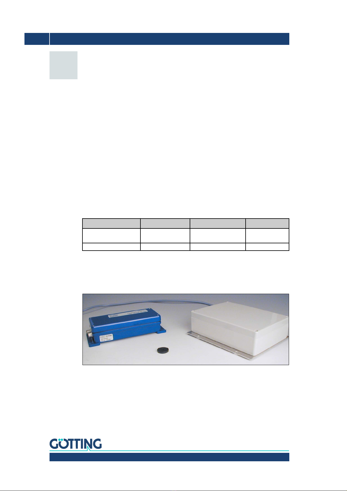
2.2 System Components.......................................................................................................... 6
2.3 Function................................................................................................................................. 7
2.3.1 Surveillance Of The Output Stage.............................................................................................. 7
2.3.2 Switchable reference transponder in the antenna................................................................ 7
2.3.3 Software Update (RS232) ............................................................................................................. 7
3 Mounting ................................................................................................. 8
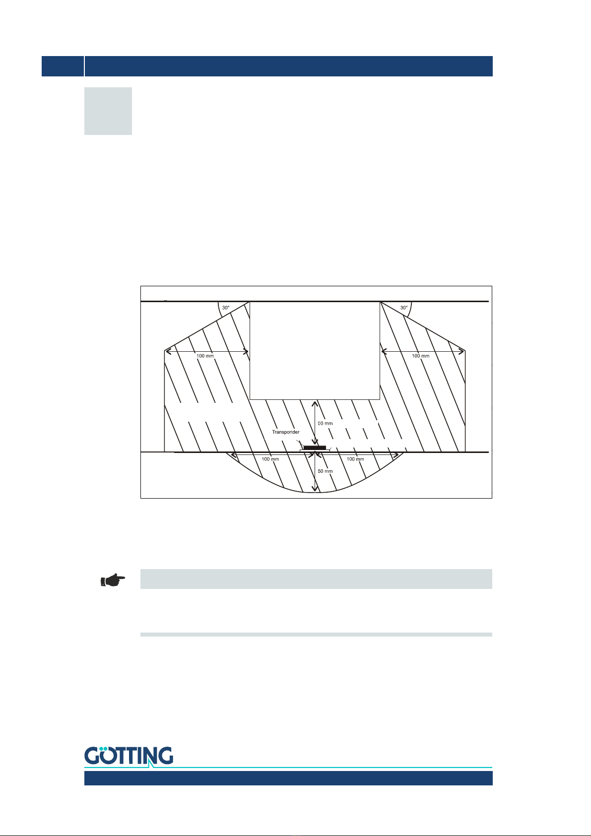
3.1 Transponder ......................................................................................................................... 8
3.2 Interpreter ............................................................................................................................. 9
3.2.1 HG G-71912ZA ................................................................................................................................. 9
3.2.2 HG G-71912YA ................................................................................................................................. 9
3.2.3 HG G-71912XA ...............................................................................................................................10
4 Commissioning ..................................................................................... 11
5 Components and Operation ................................................................ 15
5.1 Underground components .............................................................................................15
5.2 Antenna................................................................................................................................16
5.3 Interpreter HG G-71912-A .............................................................................................16
5.3.1 Pin Allocations / LED ....................................................................................................................17
5.3.1.1 8 pin jack Interpreter <–> Processor....................................................................................17
5.3.1.2 HG G-71912YA: Alloc. of the 26 pin round ribbon cable/ SUB-D connector...........17
5.3.1.3 Control LED..................................................................................................................................18
5.3.2 Interfaces .........................................................................................................................................18
5.3.2.1 RS 232 ...........................................................................................................................................18
5.3.2.1.1 List of System Data that may be Output .....................................................................18
5.3.2.1.2 List Of System Commands ..............................................................................................20
5.3.2.1.3 System Monitor ...................................................................................................................21
5.3.2.2 Positioning Pulse (all Variants) ..............................................................................................21
5.3.2.3 CANopen® (Version HG G-71912ZA/XA)............................................................................21
5.3.2.4 Parallel Port (Version HG G-71912YA) ................................................................................29
6 Software ................................................................................................30
6.1 Terminal Program .............................................................................................................30
6.1.1 Parameter Presetting ...................................................................................................................30
6.2 System Monitor .................................................................................................................31
6.2.1 How to start the monitor program ...........................................................................................31
6.2.1.1 Procedure Monitor Only...........................................................................................................31
6.2.1.2 Procedure 3964R/transparent ...............................................................................................31
6.2.2 How to work with the monitor program.................................................................................32
6.2.2.1 Main Menu ...................................................................................................................................33
6.2.2.2 (W)rite Transponder ..................................................................................................................35
6.2.2.3 (S)erial Interface .........................................................................................................................35
6.2.2.4 P(a)rallel Interface......................................................................................................................37

Device Description HG G-71912-A | English, Revision 03 | Date: 28.03.2018
4Table of Contents
6.2.2.5 (C)AN-Parameters ......................................................................................................................38
6.2.2.6 CAN Terminator ..........................................................................................................................39
6.2.2.7 P(o)sitioning Pulse .....................................................................................................................40
6.2.2.8 D(e)coding ....................................................................................................................................41
6.2.2.9 CS(V) Output................................................................................................................................41
6.2.2.10 (P)assword....................................................................................................................................42
6.2.2.11 Se(t)up Ref.transponder Values .............................................................................................42
6.2.2.12 (U)pdate Firmware .....................................................................................................................42
6.3 Software Update (Antenna Software)........................................................................ 43
6.3.1 Configuring the Update Program..............................................................................................43
6.3.2 Proceeding a Software Update..................................................................................................43
7 Trouble Shooting.................................................................................. 45
8 Technical Data ...................................................................................... 46
9 Appendix ............................................................................................... 47
A Physical Basics.......................................................................................................................................47
A.1 Field Arrangement of the Energy Field.......................................................................................................47
A.2 Field Arrangement of the Transponder’s Return Signal .....................................................................47
A.3 Induced Voltages in Sum and Difference Antenna...............................................................................48
B Procedure 3964R .................................................................................................................................. 48
B.1 Data direction antenna -> PLC .......................................................................................................................48
B.2 Data direction PLC -> Antenna.......................................................................................................................49
C Procedure "transparent"..................................................................................................................... 49
C.1 Data direction antenna -> PLC .......................................................................................................................50
C.2 Data direction PLC -> antenna .......................................................................................................................50
D Parallel Output........................................................................................................................................ 50
E Positioning Pulse...................................................................................................................................50
F Timing-Diagramm of the parallel interface ...............................................................................51
10 List Of Pictures..................................................................................... 52
11 List Of Tables........................................................................................ 53
12 Index ...................................................................................................... 54
13 Copyright and Terms of Liability ........................................................ 56
13.1 Copyright ............................................................................................................................ 56
13.2 Exclusion of Liability ....................................................................................................... 56
13.3 Trade Marks and Company Names............................................................................. 56

Device Description HG G-71912-A | English, Revision 03 | Date: 28.03.2018
5About this Document – Chapter 1
1About this Document
The following symbols and formatting are used in Götting documentations:
Note
Indicates technical information that should be followed when using the device.
ATTENTION!
Indicates dangers that may lead to damages or the destruction of the device.
BEWARE!
Indicates dangers that may lead to injuries or severe damage of property.
WARNING!
Indicates dangers that may lead to injuries, potentially with loss of life, or severe damage of
property.
Tip
Indicates information that makes handling of the device easier.
Link
Indicates additional information in the internet, e.g. on our homepage www.goetting-
agv.com. Those links are clickable in the PDF version of this documentation.
Program texts and variables are indicated through the use of a fixed width
font.
Whenever the pressing of letter keys is required for program entries, the required
etter eys are indicated as such (for any programs of Götting KG small and capital
letters are equally valid).

Device Description HG G-71912-A | English, Revision 03 | Date: 28.03.2018
6Chapter 2 – Introduction
2Introduction
The herein described system is especially suited for indoor areas. The electronic units are
not sealed within the antenna cases, but varnished. Therefore it is possible to effect all im-
portant settings and adjustable values after manufacturing. This leads to fair priced sys-
tems. Software updates can be effected using a serial interface.
The interpreter HG G-71912-A supplies the transponder code as a serial signal or parallel
signal as well as a midpoint crossover pulse when crossing over a transponder, which is re-
producible very exactly.
The transponders used in this system are HW DEV00095/HW DEV00098 or HG G-71325XA
(read / write). These transponders are fair priced and especially suited for the applications
of this system (track guided or rail-mounted vehicles with fairly small reading distances).
This manual refers to equipment with software version 1.08.
2.1 Interpreter Variants
The interpreter is available in three different variants:
2.2 System Components
The following components which all match the evaluation unit (see no. 3) are offered:
Figure 1 System components
1. Transmitting/receiving antenna HG G-98767ZA (different antennas can be used in
this system)
2. Transponder HW DEV00095/HW DEV00098 or Götting HG G-71325XA (on the track)
3. Interpreter HG G-71912-A
4. Optional programming device for transponders HG 81830YA (not shown in picture)
Variant HG G-71912 ZA YA XA
Output serial
CANopen®parallel
serial
serial
CANopen®
Mounting Aluminium flange Aluminium flange Plastic plate
Table 1 Variants: interpreter HG G-71912

Device Description HG G-71912-A | English, Revision 03 | Date: 28.03.2018
7Introduction – Chapter 2
2.3 Function
As the antenna passes over the transponder, it energizes the latter with an energy field of
128 kHz. The transponder returns its code at half of this frequency.
The transponder position in relation to the antenna surface is measured by a coil with ori-
entation in direction of travel. The interpreter decodes the transponder code. Each crossing
of the coordinate axis in driving direction generates a positioning pulse with an adjustable
duration.
The serial output signal is a non-voltaic RS 232. Alternatively it is possible to use a CAN bus.
The positioning pulse is not galvanically separated but available as a +24 V (20 mA) opera-
tional voltage switched output. Optional a 15 bit parallel output for the code (24 Volt
switched, non current limiting) can be effected.
Transponders may also be programmed. Therefore the transponder has to be located within
the antenna field at least 30 ms after starting the programming cycle.
2.3.1 Surveillance Of The Output Stage
The output stage is surveilled concerning the following errors:
– capacity of oscillatory circuit, short circuit, idling, detuning
– oscillator breakdown 128 kHz, frequency deviation
– short-circuit transmitting conductor, idling
– power transistor is defect
By this surveillance with a certain probability the function can be detected. Defective con-
tacts or ripped-off cables between interpreter and antenna are checked constantly. A non-
authorized change in parameters leads to the setting of a bit in the system status (see also
Tabelle 7 auf Seite 19).
ATTENTION!
Also the crossing of a massive steel plate may possibly trigger the surveillance!
After programming the transponder an error bit is set, as the surveillance circuit reacts to
the altitude modulation (AM) of the output stage, which is created for programming the
transponder. The error bit is deleted by a successful reference transponder test.
2.3.2 Switchable reference transponder in the antenna
It is recommended that in front of each starting and each change of driving direction a ref-
erence transponder test is proceeded via a serial command. That way, the complete func-
tion of the antenna and of the interpreter is checked cyclically. If the test has been success-
ful, a positioning pulse is output.
2.3.3 Software Update (RS232)
Until up to 10 seconds after turning on the device, an update can be started by using a spe-
cial PC program without opening the system monitor. Additionally, there is a submenu for
the software update in the system monitor (see also chapter 6.3 on page 43).

Device Description HG G-71912-A | English, Revision 03 | Date: 28.03.2018
8Chapter 3 – Mounting
3Mounting
3.1 Transponder
The maximum reading distance for all transponders can only be achieved when the mini-
mum distance to metal surfaces is maintained. There are some transponder types especial-
ly optimized for the mounting directly on metal. To clarify the configuration, it is essential to
carry out tests!
As mentioned above, it is recommendable to maintain the minimum distances within the
metal-free area (Figure 2). The impact on positioning accuracy and range also depends on
the size and distance of metal parts.
Figure 2 Minimum spacings around the transponders (on-track mounting) and the antenna HG G-
98767ZA
Alternatively the transponder can be mounted level with the road. In this case, the antenna
has to be placed into an accordingly lower position to ensure the nominal reading distance.
Note
Electric power lines (for example for charging points) may not be passed in this area, as the
reading of the code will be complicated or the code will be falsified by pulses which may
occur.
Antenna
metal-free area
reading distance
isolation and distance plate (optional)
vehicle
track

Device Description HG G-71912-A | English, Revision 03 | Date: 28.03.2018
10 Chapter 3 – Mounting
3.2.3 HG G-71912XA
Figure 5 Dimensions: interpreter HG G-71912XA
180 mm
85 mm
44 mm
GÖTTING KG
Celler Str. 5, 3 1275 Lehrt e
PWR
CD
POS
ERR
DATA
TAG R/W-Unit
HG 71912-A
196 mm
65 mm
220 mm
105 mm
10 mm
7,5 mm
Ø 5,5 mm
Ø 12 mm
Isolationsplatte
54 mm

Device Description HG G-71912-A | English, Revision 03 | Date: 28.03.2018
11Commissioning – Chapter 4
4Commissioning
Note
Check the operating voltage before connecting! Although the RS 232 interface reacts large-
ly insensitive to interferences, the cable should not be located directly beside power supply
cables.
Connect all necessary cables. For the next commissioning steps connect a laptop with the
antenna. Then start the monitor program as described in section 6.2 on page 31.
1. Move the transponder below the antenna
In the status line the voltage S has to rise significantly. The code has to be detected
immediately and the number of readings has to be counted up to 255 constantly.
When the transponder crosses the center axis of the antenna in driving direction, a
positioning pulse has to be generated.
2. Remove the transponder from below the antenna
If there is no transponder in the field, the voltage S has to fall to extremely small val-
ues. The code display and an possible display of the number of readings remain. If
that is not the case, interferences in a frequency range of 64 kHz are induced.If no
errors occurred, the monitor program can be closed. Remember to save possibly
altered values. After changing certain parameters, a system reset is required (turn-
ing off and on the antenna). This procedure is explained in the corresponding chapter
of the monitor program (see chapter 6.2 „System Monitor“ on page 31).
3. Now proceed an one-time reference transponder setup by transmitting the corre-
sponding serial command (see Tabelle 5.3.2.1.2 auf Seite 20) or by using the corre-
sponding submenu in the monitor program (see Tabelle 6.2.1 auf Seite 31).
Note
This command may only be carried out once during the commissioning, as otherwise
changes in the accuracy of the antenna remain undiscovered, as they are included in the
reference values each time a setup of the reference transponders is proceeded!
The new reference values, found during the reference transponder setup (sum. and differ-
ence voltage), are saved automatically to the parameter E2PROM when applying the serial
command.
4. Now, it is recommended to protocol a complete drive. Depending on the antenna ver-
sion there are different possibilities:
Parallel interface (in the interpreter version HG G-71912YA)
Here, a logging is possible via a serial interface (see chapter 6.2.2.9 on page 41).
CAN-Bus (in the interpreter version HG G-71912ZA, XA)
Here, a logging is possible via a serial interface (see chapter 6.2.2.9 on page 41).

Device Description HG G-71912-A | English, Revision 03 | Date: 28.03.2018
12 Chapter 4 – Commissioning
In the following diagrams examples for registered data are shown:
Figure 6 Diagram: commissioning protocol / low interference; sum voltage over track
In the diagram the sum voltage over the track is shown. The noise (interference) level is lo-
cated at 50 samples, the signal at 950. The decoding of the transponder is faultless, as also
shown in the following picture.
Figure 7 Diagram: commissioning protocol / undisturbed decoding of the transponder
When crossing a transponder the sum voltage rises. After exceeding the Threshold for De-
coding the bit TRANS_IN_FIELD is set. After 4 x 8 ms ( = four data points) is transponder
code is decoded. The duration depends on the settings made under Number of Equal Codes
in the submenu Time & Code. In this example 2is chosen, that means that the input code
is compared with the two precedent codes.
Low interference level
Undisturbed decoding of the transponder

Device Description HG G-71912-A | English, Revision 03 | Date: 28.03.2018
13Commissioning – Chapter 4
After crossing the center of the antenna the POSI pulse is triggered. Its duration is termi-
nable. The bits TRANS_IN_FIELD and CODE_OK are deleted, as soon as the sum voltage
falls below the Threshold for Decoding. In this example a reserve from 6 x 8 ms for trigger-
ing the POSI-Puls is left. The crossing velocity is approx. 0.87 m/s (140 mm length of anten-
na / 20 x 8 ms).
In the following protocols the impacts of a high interference level can be seen.
Figure 8 Diagram: commissioning protocol / high interference; sum voltage over track
The interference level reaches up to 300 samples. At transponder 207 the noise is due to a
charging station so high, that it even influences the transponder signal. As an impact it takes
9x 8 ms until the transponder 203 is decoded (see Figure 9 on page 14). This is sufficient
for a slow crossing velocity of 0.5 m/s (140 mm / 33 x 8 ms) to generate a POSI pulse, in
contrast a velocity of 1 m/s is to high, this transponder cannot be crossed with such a ve-
locity.
High interferece level

Device Description HG G-71912-A | English, Revision 03 | Date: 28.03.2018
14 Chapter 4 – Commissioning
Figure 9 Diagram: commissioning protocol / disturbed decoding (but still functional)
In the following diagram it is shown how a false set Threshold for Decoding or Threshold for
Positioning can cause erroneous POSI pulses.
Figure 10 Diagram: commissioning protocol/POSI-Pulse triggered by noise & too high Thresh.
In this example the thresholds are set to 100 samples. The bit TRANS_IN_FIELD is set con-
stantly. After a successful decoding a correct POSI pulse is triggered. As the software does
not know, that the antenna field is left then, each further zero crossing of the difference sum
generates a new POSI pulse.
Disturbed decoding (function still available)
POSI-Pulse triggered by noise & too high threshold

Device Description HG G-71912-A | English, Revision 03 | Date: 28.03.2018
15Components and Operation – Chapter 5
5Components and Operation
5.1 Underground components
Transponders of the type HW DEV00095/HW DEV00098 or HG G-71325XA may be used as
reference points. All described RW transponders can be programmed using the reading an-
tennas or an optional programming device of the type HG G-81830YA.
Range and accuracy of the system are influenced by:
– any large metal pieces (sheets) on the ground
– proximity of any floor reinforcement (see chapter 3 „Mounting“ on page 8, section 3.1
„Transponder“ on page 8)
– Inductive loops, as they are created e.g. by steel building mats have a great influence.
Individual metal poles have little effect. Those may be partly within the metal-free
area (see Figure 2 on page 8).
– Cable with pulsed currents with spectral parts between 64 kHz ±4 kHz
– The following environmental conditions have no effect on the system:
–Snow,ice,water
– Oil, tar, earth, dirt, etc.
Code structure
The code length is 20 bit of useful data. The system decodes and outputs the entire code
string; when using the parallel interface only the 15 lowest bits are output. The data protec-
tion within the trovan™ transponders is done by line (of 3 bit each) and column parity. To
achieve a better data protection, it is therefore recommended to implement an additional
code check when using RW transponders. The transmission duration for one complete tele-
gram is 8 ms for both types.

Device Description HG G-71912-A | English, Revision 03 | Date: 28.03.2018
16 Chapter 5 – Components and Operation
5.2 Antenna
In general, different antennas which are all described within their own device descriptions
can be used with this interpreter (the right device description has been delivered with the
system), but at the moment, there is only one matching type:
– HG 98767ZA - this antenna has an effective antenna surface of 130 x 180 mm and
allows a crossing velocity of 2 m/s (with positioning pulse)
5.3 Interpreter HG G-71912-A
Figure 11 Interpreter HG 71912-A (shown: version HG 71912ZA with serial interface)
The electronics of the interpreter are cased in a aluminium housing (206 x 87 x 48 mm incl.
fastenings clips). The antenna can be connected via a 9 pin jack. The interpreter can also be
connected to the processor of the device via a 8 pin plug. The connections can be found on
the front end of the device. Concerning the interfaces and cables the following variants are
available:
Variant Description
HG G-71912ZA serial interface & CAN bus with 8 pin panel jack
HG G-71912YA Parallel and serial interface with cable and 25 pin Sub-D plug
HG G-71912XA like variant ZA, but fastening via plastic plate
Table 2 Overview variants: Interpreter HG G-71912-A

Device Description HG G-71912-A | English, Revision 03 | Date: 28.03.2018
17Components and Operation – Chapter 5
5.3.1 Pin Allocations / LED
5.3.1.1 8 pin jack Interpreter <–> Processor
5.3.1.2 HG G-71912YA: Alloc. of the 26 pin round ribbon cable/ SUB-D connector
Note
The metal parts of the Sub-D connecter are connected to the shielding of the cable and the
casing and should be positioned.
The contacts are allocated as follows:
No. Colour Description
1white +24 V
2brown GND
3green CAN H
4yellow CAN L
5grey POSI
6pink TxD (RS232)
7blue RxD (RS232)
8 – shielding
Table 3 Allocation 8 pin jack Interpreter <–> Processor
Lead # Contact #
(SUB-D)
Allocation
(SUB-D)
1 1 Data Ready
214 D14
3 2 D13
415 D12
5 3 D11
616 D10
7 4 D9
817 D8
9 5 D7
10 18 D6
11 6D5
12 19 D4
13 7D3
14 20 D2
15 8D1
16 21 D0
17 9TxD (RS232)
18 22 RxD (RS232)
19 10 POSI
20 23 not connected
21 11 +24V
22 24 +24V
23 12 GND
Table 4 Alloc. of the 26 pin round ribbon cable/of the SUB-D connector (part 1 of 2)

Device Description HG G-71912-A | English, Revision 03 | Date: 28.03.2018
18 Chapter 5 – Components and Operation
5.3.1.3 Control LED
There are five control LEDs.
5.3.2 Interfaces
5.3.2.1 RS 232
The serial output may be configured in several ways. The transmission rate is adjustable be-
tween 9600 and 19200 Baud, the output protocol may be chosen as either "transparent" or
"3964 R" (see also sections B on page 48 and C on page 49). Apart from that, the content
of the telegrams is configurable, as the user may choose from a list of parameters. Serial
commands are used for activating a system monitor.
5.3.2.1.1 List of System Data that may be Output
A telegram of the serial RS 232 output consists of max. 13 bytes.
The minimum update rate at 9.6 KB is then calculated as follows:
Figure 12 Formula: Minimum update rate
As the transmission is binary, it is possible – when using the 3964R procedure – to add fur-
ther (DLE) characters by this procedure.
All multiple byte variables are output either with the highest byte or the lowest byte first (ad-
justable)! The 8 bit check sum is only output when using the transparent protocol. It then
includes the start character. The start character, as well as the check sum (transparent pro-
tocol) cannot be removed from the data block.
24 25 GND
25 13 Chassis
26 - Chassis
LED Colour Function
PWR yellow shows the current operating voltage
CD yellow lit, when the receiving voltage exceeds <Threshold for Decoding>
DATA yellow Blinks, if transponder approaches (also at noise), is lit constantly
when the transponder is read reliable
POS green represents the positioning output
ERR red is lit when the error bits DEC_HW_ERR, PARAM_ERROR or
ANTENNA_ERR are set or when the reference transponder test
was unsuccessful
(see also Table 7 on page 19)
additional CANopen®-Function:
- lit: permanent CAN bus error (bus offline)
- blinks slowly: CANopen®state preoperational
- blinks quick: CANopen®state stop
Table 5 Control LED
Lead # Contact #
(SUB-D)
Allocation
(SUB-D)
Table 4 Alloc. of the 26 pin round ribbon cable/of the SUB-D connector (part 2 of 2)
13 Byte
Telegramm
------------------------------11 Bit
Byte
------------9600Bit
s
-------
14 9 ms
Telegramm
------------------------------
=.

Device Description HG G-71912-A | English, Revision 03 | Date: 28.03.2018
19Components and Operation – Chapter 5
The protocol is adjustable, irrespective of whether telegrams are put out permanently by an
adjustable update rate or whether one transponder is located within the field.
Table listing the data words of a telegram of 12 (13) byte length:
The following table shows a list of the binary codes used to describe the system status (for
bytes # 11 and 12 from Table 6):
*)
Example:
Error 0006 means CODE_ERROR and PARAM_ERROR.
Byte # Length Valuehex Type Description
11 Byte 1unsigned char start sign ASCII-061: "="
2,3,4,5 4 Byte 2unsigned long 32 bit transponder code
6,7 2 Byte 4unsigned int voltage generated by transponder in frame
antenna in samples
8,9 2 Byte 8signed int voltage generated by transponder in differ-
ence antenna in samples
10 1 Byte 10 unsigned char number of code readings of last transponder
crossing
11,12 2 Byte 20 unsigned int systems status in binary coding
(13) 1 Byte unsigned char check sum (only at transparent protocol)
Table 6 Data words of a telegr. w. 13 byte length (equals 12 data bytes)
Value Name Description
0001 DEC_HW_ERROR hardware of code decoder erroneous
0002 CODE_ERROR transponder code received with check sum error
0004 PARAM_ERROR checks sum of parameters in E²PROM not correct
0008 ANTENNA_ERR voltage/frequency at antenna inductor outside specifica-
tion *).
0010 REF_TRANS_ON hint, that the reference transponder is active (test in pro-
cess)
0020 REF_TEST_OK reference transponder test was successful **)
0040
0080 TOGGEL see description "CANopen®" in chapter 6.2.2.5 on page 38
0100 RW_TRANSPONDER transponder is writable
0200 TRANS_IN_FIELD transponder is being detected ***)
0400 CODE_OK code decoded without errors ***)
0800 SEG- transponder below connected half of antenna
1000 POSIPULS transponder crossed center of antenna ***)
2000
4000
8000 RESET PowerOn or Watchdog Reset proceeded ****)
– *) Is deleted, as soon as voltage and frequency correspond to the specifications.
– **) The values for code, Us and Ud equal the saved values. The bit remains set until
the next test and is deleted by unsuccessful reference transponder test.
– ***) These bits are deleted as soon as the transponder leaves the antenna field.
– ****) Is deleted at the first call of the reference transponder test.
Table 7 Possible system notes / error messages

Device Description HG G-71912-A | English, Revision 03 | Date: 28.03.2018
20 Chapter 5 – Components and Operation
Note
Error 0002 may also occur during ordinary transponder crossings, if the code transmission
is aborted due to decreasing power output level.
5.3.2.1.2 List Of System Commands
A Command telegram always consists of four bytes, including the command itself, its pa-
rameters and at last the check sum (XOR relation of all bytes with starting sign). When
choosing the procedure "transparent" (see also appendix, see page C on page 49) also a
start sign has to be sent.
Four commands are defined:
Note
No. 1:The monitor mode should not be used in normal mode (for example from a PLC) as
the following data output will not be realized in transparent or 3964R mode. It is suited for
the VT52 terminal, which can be used to alter parameters.
Note
No. 4: The comparative values (sum and difference voltage) are saved automatically in the
parameter E²PROM. This command should only be proceeded once during commissioning,
as otherwise changes in the exactness of the antenna may not be noticed as at every setup
of the reference transponder test the reference values are considered!
No. Meaning Procedure Start
sign Command byte Parameter Check
sum
1
Switch to monitor mode
(described in 6.2 „Sys-
tem Monitor“ on page
31)
3964R HEX 4D16 4F164E164916
ASCII MONI
transpar-
ent
HEX 3D16 4D16 4F164E164916 3816
ASCII = M ONI 8
2
Programming the code
ttttt
x= reserved for future
applications, at the
moment variable
3964R HEX 5016 Code in the Form
xt16tt16tt16
For the Code
"12345" e.g.
011623164516
transpar-
ent
HEX 3D16 5016 0A16
3Start reference tran-
sponder test
3964R HEX 5216 541631163116
ASCII RT11
transpar-
ent
HEX 3D16 5216 541631163116 3B16
ASCII = R T11 ;
4
start reference tran-
sponder test (see also
NOTE!)
3964R HEX 5216 541653165316
ASCII RTSS
transpar-
ent
HEX 3D16 5216 541653165316 3B16
ASCII = R TSS ;
Table 8 List of system commands
Table of contents
Other Gotting Media Converter manuals