Procentec VPGate User manual

VPGate Manual
PROFINET to Serial

VPGate PROFINET to serial user manual | June 2017 | ©PROCENTEC 2/104
Content
1. PROPERTIES................................................................................................ 5
1.1 General properties.............................................................................................................................5
1.2 Electrical properties...........................................................................................................................7
1.3 Mechanical properties.......................................................................................................................8
2. Hardware installation................................................................................. 9
2.1 Connector technology .......................................................................................................................9
2.1.1 Power connector ...............................................................................................................................9
2.1.2 SERIAL connector...............................................................................................................................9
2.1.3 2 ETHERNET ports, 10/100 Mbps ....................................................................................................10
2.1.4 Digital Input .....................................................................................................................................10
2.1.5 Digital output...................................................................................................................................10
2.2 Front panel indicators......................................................................................................................11
2.3 DIP switches.....................................................................................................................................11
2.3.1 Default configuration.......................................................................................................................11
2.3.2 Selecting the RS-232/RS-485 modes ...............................................................................................12
2.3.3 Termination resistance....................................................................................................................13
3. SOFTWARE CONFIGURATION ................................................................... 14
3.1 Configuration tools of the PROFINET IO controller .........................................................................14
3.2 Integrating VPGate into a project....................................................................................................14
3.2.1 Importing a GSDML file into the engineering tool...........................................................................14
3.2.2 Integrating VPGate ..........................................................................................................................14
3.3 General configuration of VPGate.....................................................................................................16
3.3.1 General parameters.........................................................................................................................16
3.4 Configuration in TRANSPARENT mode ............................................................................................18
3.4.1 Inserting and configuring modules in the TRANSPARENT mode.....................................................21
3.5 Configuration in MODBUS Master mode ........................................................................................24
3.5.1 Inserting and configuring modules in the MODBUS Master mode .................................................25
3.5.2 Behaviour of the MODBUS Master according to PROFINET status .................................................29
3.6 Configuration in the MODBUS Slave mode .....................................................................................30
3.6.1 Inserting and configuring modules in the MODBUS Slave mode ....................................................32
4. Diagnostic................................................................................................. 34
4.1 Diagnostic on the UDP 5628810 port ...............................................................................................34
4.2 PROFINET diagnostic........................................................................................................................35
4.3 Diagnostic Digital output .................................................................................................................36
5. Digital inputs/outputs .............................................................................. 38
5.1Digital output...................................................................................................................................38
5.2 Digital input .....................................................................................................................................38
6. IP address configuration........................................................................... 40
6.1 Configuration via the DCP protocol .................................................................................................40
6.2 Default configuration.......................................................................................................................41
7. MRP redundancy...................................................................................... 43
7.1 Functioning in the MRP Client .........................................................................................................43

VPGate PROFINET to serial user manual | June 2017 | ©PROCENTEC 3/104
7.2 Configuration...................................................................................................................................43
8. Modbus/TCP ............................................................................................ 44
8.1 Operating principle..........................................................................................................................44
8.2 Fault management ..........................................................................................................................45
8.3 MODBUS/TCP GATEWAY TO MODBUS SERIAL mode......................................................................45
8.3.1 Operating principle..........................................................................................................................45
8.3.2 Fault management ..........................................................................................................................46
9. Web server............................................................................................... 47
9.1 Configuration web page ..................................................................................................................47
9.2 Account management on the web server .......................................................................................48
9.3 System information menu ...............................................................................................................49
9.4 Network settings menu ...................................................................................................................49
9.5 SNMP information menu.................................................................................................................50
9.6 Ethernet statistics menu..................................................................................................................50
9.7 PROFINET menu...............................................................................................................................53
9.8 MODBUS menu................................................................................................................................54
9.9 File system menu.............................................................................................................................55
9.10 Firmware upload menu ...................................................................................................................56
9.11 Reboot menu ...................................................................................................................................57
9.12 Passwords menu..............................................................................................................................57
9.13 Logout menu....................................................................................................................................58
9.14 Customized WEB pages ...................................................................................................................58
9.15 Accessing data via personalised WEB pages ...................................................................................58
9.16 An example of customised WEB pages............................................................................................59
10. FTP SERVER .............................................................................................. 61
11. SNMP agent ............................................................................................. 62
12. Appendices............................................................................................... 64
13. Other PROCENTEC products..................................................................... 95
14. Sales offices and distributors.................................................................... 97
15. About PROCENTEC ................................................................................. 102
16. Notes...................................................................................................... 103

VPGate PROFINET to serial user manual | June 2017 | ©PROCENTEC 4/104
Document version
Version
Date
Description
A
08-2012
Creation. Preliminary version
B
01-2013
Updates after proofreading and tests
C
02-2014
Updates, updated appendixes, I/O is no longer an option,
D
05-2014
Updated SNMP, appendix E on SNMP MIB2, added behaviours on
PROFINET stop, link-down and startup, FSU deleted as not tested
E
09-2014
Remove µSD and CAN options, updated web server chapter and GSD
pictures
F
06-2015
Added new explanation for the Interchars timeout and interframes
silence
Added web server current page auto refresh information
Corrected default FTP Login/Password
Added MODBUS web menu description
G
11-2015
Inverted Ethernet connector LEDs
H
6-2017
Corrected:
•Switch 1 to 2 on page 10
•Resistor value of 120Ωto 150Ω on page 12 and 13
•Interframe silence change from 0 to 20 ms
•Minor textual changes

VPGate PROFINET to serial user manual | June 2017 | ©PROCENTEC 5/104
1. PROPERTIES
1.1 General properties
ETHERNET LINK
Bandwidth
10/100 Mbps, auto-negotiation, auto-polarity, auto MDI/MDIX
LEDs
Active Link (orange) and activity (green)
Distances
Maximum 100 m
Cable
Shielded Industrial Ethernet (at least of category 5E)
Connectors
2 RJ-45 connectors, insulated by a transformer and shield connection
Supported protocols
PROFINET, MODBUS/TCP, SNMP V1, HTTP, FTP
Switch
2 port integrated switch
Redundancy
MRP Client
PROFINET IO Device
Conformance class
CC-B
IP address control
DCP (PROFINET) or switch in the front
Services
SNMP V1, LLDP Sender/Receiver, MRP, I&M
GSDML file
Configuration file of the device that can be downloaded from the embedded web
server or the FTP server.
Max. number of input
bytes
512 bytes
Max. number of output
bytes
512 bytes
Minimum cycle time
2 ms

VPGate PROFINET to serial user manual | June 2017 | ©PROCENTEC 6/104
MODBUS/TCP
Operating mode
Server or gateway
Gateway mode
Direct access to devices on the serial network
Max. number of
simultaneous TCP
connections
3
Port
502
MODBUS/TCP
Bandwidth
1200, 2400, 9600, 19200, 38400, 57600, 115200 baud
Data bits
7 or 8 bits
Interface
RS-232 or RS-485. Select using the switch
Distance in RS-485
Maximum of 1200 m without a repeater (depends on the bandwidth and the cable)
Cable
Shielded twisted pair
Connector
3-contact, female plug-in terminal board
Termination resistance
On the RS-485 link: 150 Ω; can be set by switch
Polarisation
On the RS-485 link: polarised line when termination resistance is activated
TRANSPARENT MODE
End frame delimiter
End of frame character, known length, on the timeout
MODBUS MODE
Bus access
End of frame character, known length, on the timeout
Protocol
MODBUS RTU or ASCII
Transmission
Half Duplex, asynchronous
Accepted functions
1, 2, 3, 4, 5, 6, 7, 15, 16, 23
MODBUS MODE

VPGate PROFINET to serial user manual | June 2017 | ©PROCENTEC 7/104
Number of addressable
slaves in the master
mode
50 MODBUS slaves
Address range
1 - 247
Number of accessible
MODBUS registers
1 - 125 registers in read-only mode
1 - 123 registers in write mode
Frequency of sending
frames
Cyclic, when changed
Local I/O
Digital input
1 insulated Digital input
Digital output
1 configurable Digital output (output from the Ethernet or Alarm output)
File system
Free space
10 MB
Access
FTP, HTTP
1.2 Electrical properties
Power supply
Supply voltage
24V DC ±10%
Consumption
1.7 W
Connector
3-contact (VCC, 0V, EARTH) female plug-in terminal board
Protection from polarity
reversals
Yes
Protection from short-
circuits
Yes

VPGate PROFINET to serial user manual | June 2017 | ©PROCENTEC 8/104
1.3 Mechanical properties
Mechanical properties
Case type
Plastic with a hatch on the front side.
IP20 –DIN rail fastening
Dimensions
120 x 100 x 23 mm (L x W x H)
Weight
130 g
Storage temperature
-25 °C .. +70 °C
Operating temperature
0 °C to +55 °C
Relative air humidity
Max. 80%

VPGate PROFINET to serial user manual | June 2017 | ©PROCENTEC 9/104
2. Hardware installation
2.1 Connector technology
Ethernet
RS-485 / RS-232
Power supply
Figure 1: Connectors on the top of the case
2.1.1 Power connector
Pin
Name
Description
1
24 V DC
Power supply 24 V ± 10%
2
0 V DC
Grounding
3
Earth
Earth
2.1.2 SERIAL connector
Pin
Name
Description
1
Rx
Rx RS-232 (VPGate < device)
2
Tx
Tx RS-232 (VPgate > device)
3
GND
RS-232 grounding
4
Shield
Earth
5
Data -
Signal Data - RS-485
6
Data +
Signal Data + RS-485
The shield of the SERIAL cable must be connected to the earth at each end in order to ensure its
resistance to electromagnetic disturbances. Pin 4 of the connector may be used. However, it is
better to use a shield connection jumper, fixed at each end of the serial cable on a grounding rod or
a bottom plate of a cabinet.

VPGate PROFINET to serial user manual | June 2017 | ©PROCENTEC 10/104
2.1.3 2 ETHERNET ports, 10/100 Mbps
Pin
Name
Description
1
Tx+
2
Tx-
3
Rx+
6
Rx-
The shield of the ETHERNET cable must be connected to the earth at each end in order to ensure its
resistance to electromagnetic disturbances. The connector body may be used. However, it is better
to use a shield connection jumper, fixed at each end of the serial cable on a grounding rod or a
bottom plate of a cabinet.
Digital OUT
Digital IN
Figure 2: Connectors at the bottom of the case
2.1.4 Digital Input
IEC61131-2 compliant, type 1:
2.1.5 Digital output
IEC61131-2 compliant:
Breaking capacity: 0.5 A
Maximum permissible current: 1.2 A
Pin
Name
Description
1
IN +
Insulated Digital input (15-24 V)
2
IN -
Insulated Digital input, ground return
Pin
Name
Description
1
OUT
Relay contact
2
OUT
Relay contact
OUT
2
1
IN
2
1
+
-

VPGate PROFINET to serial user manual | June 2017 | ©PROCENTEC 11/104
2.2 Front panel indicators
1ON: is lit when the gateway is live.
2Net1 : is lit and steady if communication has not been established on PROFINET (Bus Failure). Flashes if
there is a communication error (Diagnostic).
3Net2 : is lit and steady if communication has not been established on the serial link. Flashes if there is a
communication error (Timeout).
4RUN: flashes at 1 Hz if the program has been executed correctly. Flashes at 4Hz if the “DCP blink” command
(PROFINET command for requesting the flashing) is currently being processed.
5Tx: indicates that a frame is currently being transmitted on the serial link.
6Rx: indicates that a frame is currently being received on the serial link.
2.3 DIP switches
DIP switches enable:
•activating a default IP configuration (192.168.10.20)
•selecting the physical support of the serial link: RS-232 or RS-485
•activating a termination resistance and line polarisation
Figure 3: DIP switches
2.3.1 Default configuration
A switch enables resetting to a default configuration (@IP 192.168.10.20, mask 255.255.255.0) when the
VPGATE Ethernet is switched on. The configuration takes place as follows:
1
ON
2
Net1
3
Net2
4
RUN
5
Tx (serial link)
6
Rx (serial link)

VPGate PROFINET to serial user manual | June 2017 | ©PROCENTEC 12/104
A PROFINET IO controller might replace the IP address when VPGate is switched on if its station
name corresponds to the PLC program, even if the default IP configuration switch is activated.
2.3.2 Selecting the RS-232/RS-485 modes
A switch enables specifying the operating mode of the serial link in RS-232 or RS-485 (when delivered, VPGATE
is preset to RS-485):
RS-232 mode:
Figure 4: Serial network in RS-232 mode
This mode can only be used in case of communication between 2 individual devices (point-to-point
connection). The maximum distance in RS-232 is 15 m at 19200 baud.
RS-485 mode:
Figure 5: Serial network in RS-485 mode
This mode is used more often as it allows connection of several slaves on the bus. It also has other advantages
such as immunity to EMC disturbances and a greater inter-device distance than in RS-232. The maximum
distance in RS-485 is 1000 m.
Switch
Name
Description
1
ON
Default IP configuration
OFF
User-defined IP configuration
Switch
Name
Description
2
ON
RS-232
OFF
RS-485
150 Ω
150 Ω

VPGate PROFINET to serial user manual | June 2017 | ©PROCENTEC 13/104
2.3.3 Termination resistance
If the communication mode used is RS-485, there must be a termination resistance of 150Ω at both ends of the
network. A termination resistance is connected using DIP switches 3 and 4 (when delivered (VPGate is preset
without a termination resistance):
To ensure proper functioning of the termination, switches 3 and 4 must be in the same position.
Internal schema of the resistance and polarisation of the RS-485 bus:
Figure 6: Termination resistance and polarisation of the RS-485 bus
Switch
Position
Description
3 –4
(activation of the termination
resistance + line polarisation)
ON
Termination & polarisation
OFF
No termination & no
polarisation

VPGate PROFINET to serial user manual | June 2017 | ©PROCENTEC 14/104
3. SOFTWARE CONFIGURATION
3.1 Configuration tools of the PROFINET IO controller
VPGate PROFINET –SERIAL can be configured via the PROFINET network configuration software and is sent by
the PROFINET IO controller when the network is initialised.
The following detailed configuration was carried out using the "HW Config" configuration software of SIEMENS.
Nevertheless, the procedure is the same for all configuration software.
3.2 Integrating VPGate into a project
Before proceeding further, a project must be created in the engineering tool with a hardware configuration that
contains at least one PROFINET network and one IO controller.
3.2.1 Importing a GSDML file into the engineering tool
The GSD file allows using VPGate as a PROFINET IO device. It is called GSDML-V2-3-VPGate-20160412.xml and
can be found in the VPGate CD provided with the device.
The GSD file can also be accessed via the web server of VPGate (refer to paragraph 10).
This GSD must be imported via the PROFINET network configurator for VPGate to appear in the catalogue of
devices that can be inserted in the network.
Figure 7: Importing the GSD into the device catalogue
3.2.2 Integrating VPGate
The steps are as follows:
•Integrate VPGate into the network from the PROFINET device catalogue. The head module to be integrated
depends on the desired operating mode:
•MODBUS MASTER mode
•MODBUS SLAVE mode
•TRANSPARENT mode
VPGate PROFINET to serial user manual | June 2017 | ©PROCENTEC 15/104
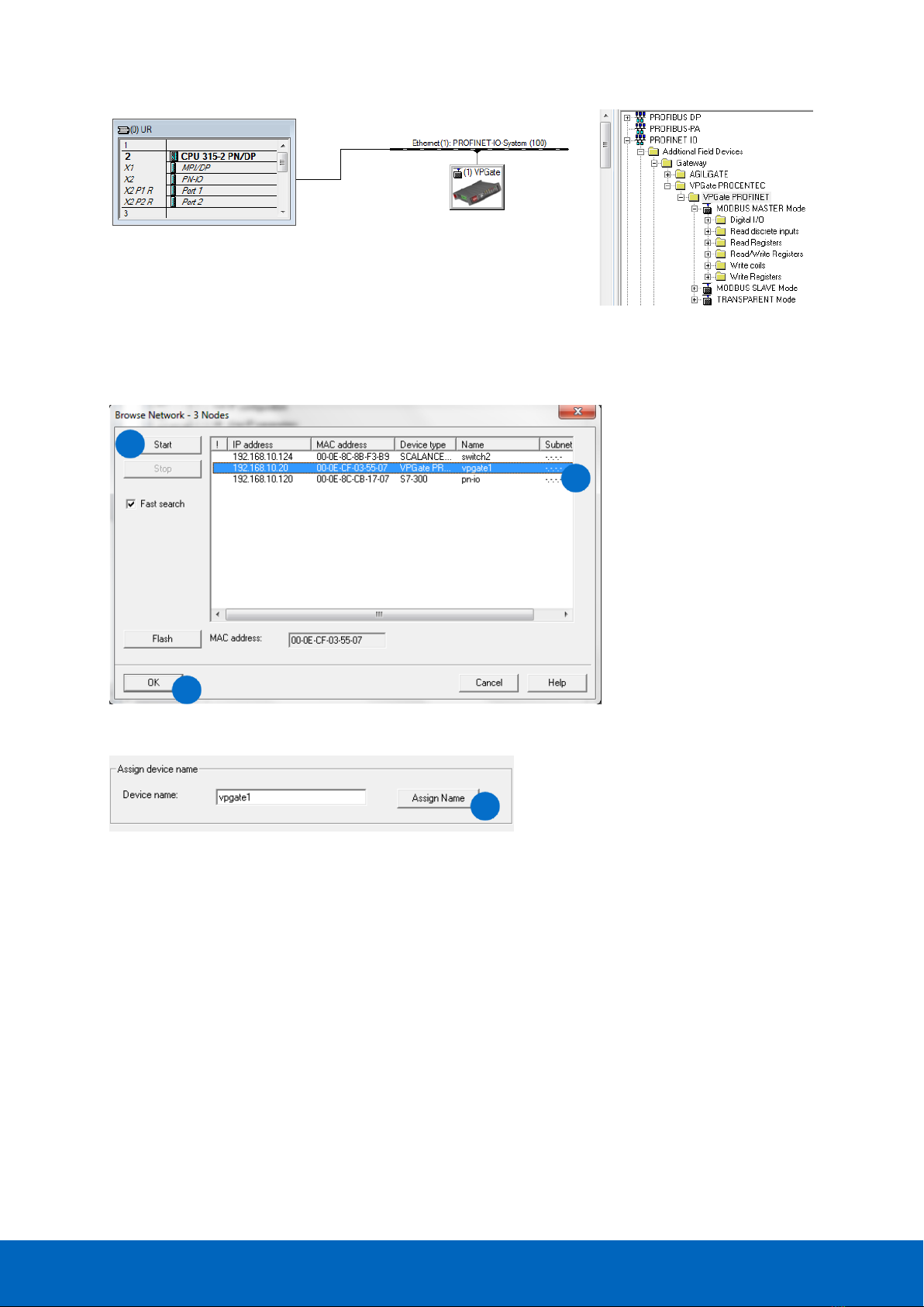
Figure 8: Integrating VPGate into the network
•Configure the desired PROFINET name (this value is configured via the DCP in VPGate). This name allows the
IO controller to identify the device when the network is switched on.
Figure 9: List of devices that can be accessed via DCP
Figure 10: Naming a device via DCP
In the device properties in the network configuration tool, define the same PROFINET name that was previously
configured in VPGate:
1
2
3
4

VPGate PROFINET to serial user manual | June 2017 | ©PROCENTEC 16/104
Figure 11:Configuring the device name in the configuration tool
The cycle time for each device in the PROFINET network is determined at the level of the IO
controller. The possible cycle times are 2, 4, 8, 16, 32, 64, 128, 256 and 512 ms.
3.3 General configuration of VPGate
3 head modules are available, each corresponding to a communication mode on the serial link:
Gateway configuration in the TRANSPARENT mode
Gateway configuration in the MODBUS Master mode
Gateway configuration in the MODBUS Slave mode
3.3.1 General parameters
The parameters described below are common for all 3 head modules.
Once VPGate is inserted in the PROFINET network, the serial link must be configured using the following
parameters:
Figure 12: Common parameters of the serial link
1
2

VPGate PROFINET to serial user manual | June 2017 | ©PROCENTEC 17/104
(*) MODBUS RTU has 8-bit data. MODBUS ASCII has 7-bit data.
Name
Description
Possible values
Baud rate
Communication speed of the serial link (in bits/s)
1200
2400
9600
19200
38400
57600
115200
Parity
Presence or absence of a parity bit
None
Even
Odd
Stop bits
Number of stop bits
1
2
Data bits (*)
Number of data bits
7
8
Timeout
Time delay before signalling the absence of data
received on the serial link
default: 1000 ms
20 –65535 ms
Interchars
timeout
Maximum time between 2 characters of a frame.
1.5 characters +
0 to 65535 ms
Interframe
silence
Time delay to be complied with after receiving a
frame, before it can be re-issued.
3.5 characters
+ 20 to 65535 ms

VPGate PROFINET to serial user manual | June 2017 | ©PROCENTEC 18/104
Defining the diagnostic management:
Figure 23: MODBUS MASTER mode diagnostic
(1): In the “Disabled” mode, the Digital output may be controlled by the “Digital Output” module if it is plugged
in.
(2): In these modes, the relay will be closed if there is a fault in the selected network:
•“On PROFINET SF” when communication with the PROFINET controller is lost.
•“On serial Link” when there is a communication error on the serial link.
•“On PROFINET and serial link SF” in case of both.
3.4 Configuration in TRANSPARENT mode
In this mode, data exchange is full duplex, without the master/slave concept. It is required to define the size of
frame received/sent by using the modules provided with the transparent mode.
The frames detected on the serial link are immediately copied in the “inputs bytes” modules plugged in
VPGate.
Similarly, if the format of a serial frame is detected in the PROFINET outputs, this frame is immediately sent on
the serial link.
For this, it is required to define the trigger for reading/sending frames in the head module “TRANSPARENT
MODE”.
Name
Description
Possible values
Diagnostic alarms
Enable or disable alarms sent by VPGate on PROFINET to the
IO controller.
Yes
No
Digital output mode
Defines the behaviour of the Digital output if the “Digital
Output” module is not plugged into an VPGate slot.
Disabled (1)
On PROFINET SF (2)
On serial link SF (2)
On PROFINET and
serial link SF (2)

VPGate PROFINET to serial user manual | June 2017 | ©PROCENTEC 19/104
For VPGate to function in the transparent mode:
•Insert the “TRANSPARENT mode” head module:
Figure 14: Inserting the “TRANSPARENT Mode” head module
•Then adapt the different parameters of the transparent mode:
Figure 15:TRANSPARENT Mode parameters

VPGate PROFINET to serial user manual | June 2017 | ©PROCENTEC 20/104
(1): If this parameter is set to User defined, the end of frame character taken into account is the one specified
by the “User defined EOF” parameter. If it is set to “on timeout”, the reception timeout taken into account is
the one defined in the configuration of the serial link.
(2): If the parameter “EOF delimiter” is set to “on timeout”, only the frames received on the serial link will be
detected on timeout. On the PROFINET side, the 1st byte must is used to specify the length of the sent/received
frame (refer to paragraph 3.4.1). This byte is not transferred on the serial link.
(3): If the parameter “EOF delimiter” is set to “length in 1st byte” or to “on timeout”, the padding value is 0x00.
(4): This counter is used as a trigger:
•If this parameter is activated, the 1st byte of the PROFINET outputs must be a counter which is incremented
each time data is available and is to be sent. The usable data starts from the 2nd byte. If there is no counter,
the frame is re-copied from the 1st byte as soon as a change in the PROFINET outputs is detected.
Name
Description
Possible values
EOF delimiter (1)
Defines how an end of frame will be detected
NULL (0x00)
SPACE (0x20)
LF (0x0A)
CR (0x0D)
CR LF
User defined
Length in 1st byte (3)
On timeout (2) (3)
User defined EOF
ASCII code of the end of frame character (where
“EOF delimiter” = User defined)
0 to 255
Add frames counter (4)
Defines whether a frame counter is added at the
start of the PROFINET input and output frames.
Enabled
Disabled
Add and control CRC 16
Specifies whether a CRC16 should be controlled in
the data received on a serial link and added at the
end of the data sent to the device on the serial
link.
Enabled
Disabled
Timeout (in ms) (5)
Time that enables detecting an end of frame when
the EOF Delimiter parameter is set to “On
timeout”.
def: 1000 ms
0 to 65535 ms
Other manuals for VPGate
3
Table of contents


