Gotting HG G-31500-A User manual

Device Description HG G-31500-A | English, Revision 02 | Date: 10.06.2021
2Overview
Basic characteristics of the audio player HG G-31500-A:
Audio player for automated guided vehicles (AGV)
Control via CAN / digital inputs
(PLC) / serial (RS 232) / buttons (function test)
Voltage supply range: 10 – 30 VDC
Supported formats: MP3/WAV
Slot for an USB stick with audio files, up to 255 files usable in the memory
medium‘s root directory
Nominal output: 2 x 10 watt @ 4 Ohm (peak output max. 2 x 25 watt, to be
taken into consideration when selecting loudspeakers)
Potentiometer for limiting the maximum volume
Configuration of interface parameters
Installation via mounting lugs / optionally top-hat rail mounting (s. Variants, sec-
tion 3.1 on page 8)
© 2021 Götting KG, errors and modifications reserved.
The Götting KG in D-31275 Lehrte has
a certified quality management system
according to ISO 9001.

Device Description HG G-31500-A | English, Revision 02 | Date: 10.06.2021
3
Table of Contents
Contents
1 About this Document........................................................................ 4
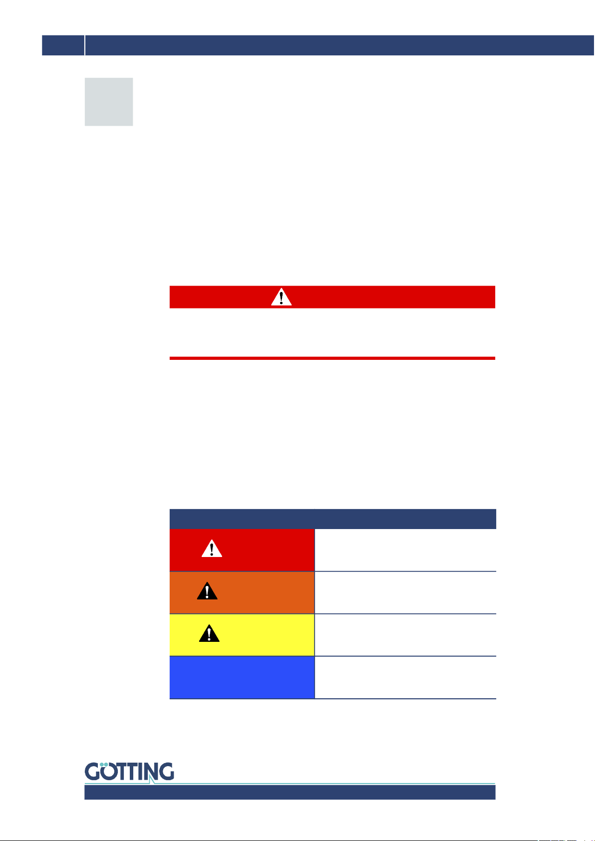
1.1 Warning Notices.................................................................................................................... 4
1.2 Symbols ................................................................................................................................... 5
2 Introduction....................................................................................... 6
2.1 Connection Overview .......................................................................................................... 6
2.2 Interfaces................................................................................................................................. 6
3 Hardware ........................................................................................... 8
3.1 Variants .................................................................................................................................... 8
3.2 Factory Settings .................................................................................................................... 8
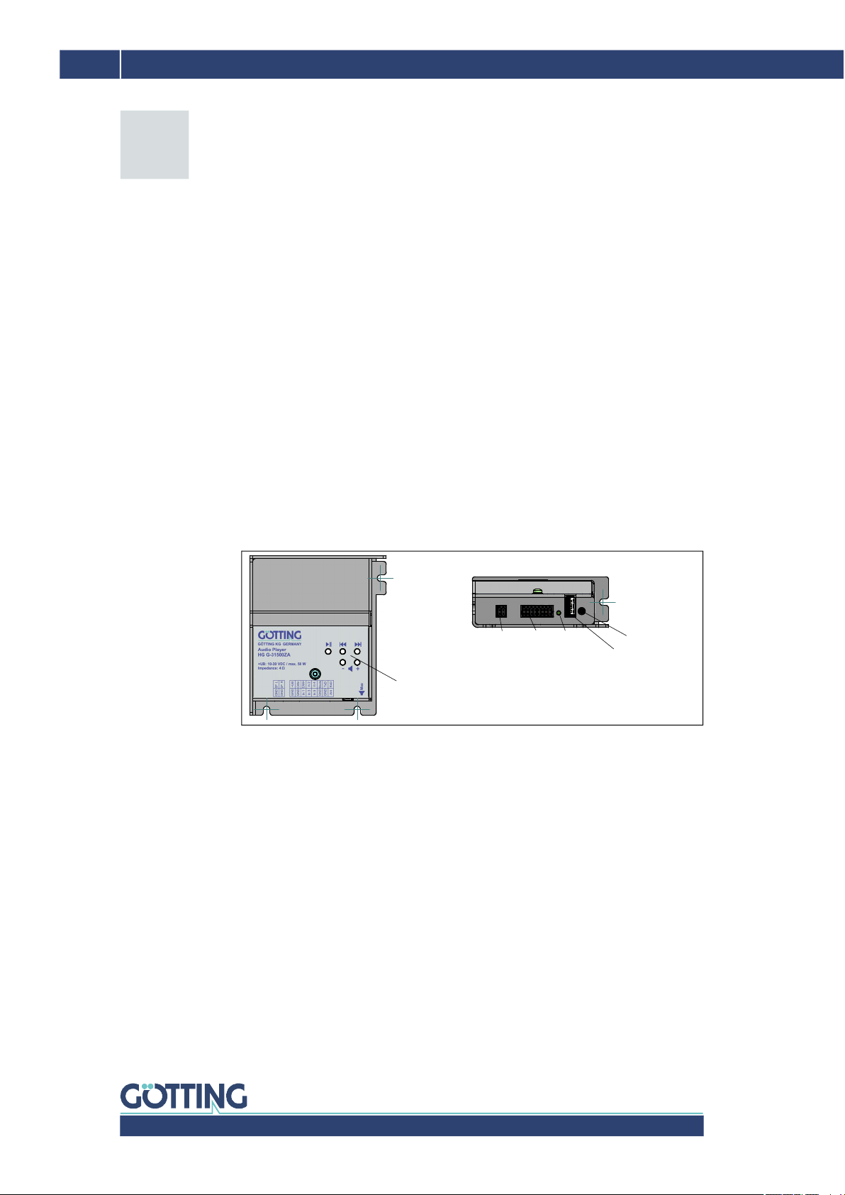
3.3 Operating Elements / Connectors ................................................................................... 8
3.4 LED ............................................................................................................................................ 9
3.5 Pin Assignments ST 1 & ST 2 ........................................................................................... 9
3.5.1 ST 1 Loudspeaker............................................................................................................. 9
3.5.2 ST 2 Supply & Interfaces ............................................................................................... 9
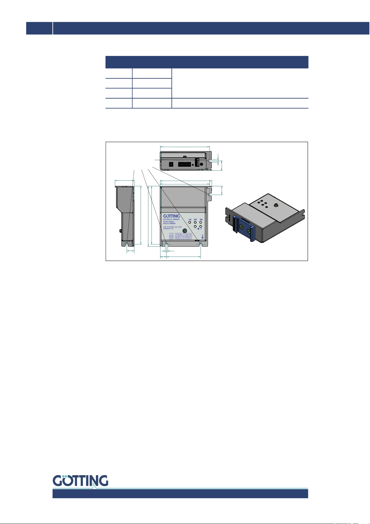
3.6 Mounting ...............................................................................................................................10
3.7 Audio Amplifier....................................................................................................................10
3.8 Selection Mono/Stereo .....................................................................................................10
3.9 Potentiometer ......................................................................................................................10
3.10 Standby Mode......................................................................................................................11
3.11 Commissioning ....................................................................................................................11
4 Audio Control: Interfaces, Telegrams & Buttons.......................... 12
4.1 Audio Files on the USB Storage Medium .................................................................... 12
4.2 Digital Inputs ........................................................................................................................12
4.3 Serial Interface RS 232 .....................................................................................................13
4.4 CAN Bus.................................................................................................................................13
4.5 Bit Coded Control Byte (Serial & CAN Bus) ................................................................14
4.6 Button Panel.........................................................................................................................14
5 Configuration / Firmware Update .................................................. 15
5.1 Release Notes ......................................................................................................................15
5.2 Configuration via CONFIG.INI .........................................................................................15
5.3 Firmware Update/Downgrade ........................................................................................16
6 Technical Data ................................................................................ 17
7 List of Figures ................................................................................. 18
8 List of Tables................................................................................... 19
9 Index ................................................................................................ 20
10 Copyright and Terms of Liability ................................................... 21
10.1 Copyright ...............................................................................................................................21
10.2 Exclusion of Liability ..........................................................................................................21
10.3 Trade Marks and Company Names ............................................................................... 21

Device Description HG G-31500-A | English, Revision 02 | Date: 10.06.2021
4Chapter 1 – About this Document
1About this Document
For you to be able to use your product simply and safely this device description uses
consistent warning notices, symbols, terms and abbreviations. Those are described
in the following sections.
1.1 Warning Notices
In this device description warning notices appear before sequences of actions that
may lead to damage to persons or property. The listed actions for the danger preven-
tion have to be observed.
Warning notices have the following structure:
The warning symbol (warning triangle) indicates danger to life or risk of injury.
The signal word indicates the severity of the danger.
The paragraph kind or source of the danger names the kind or source of the
danger.
The paragraph consequences describes the consequences of not observing
the warning notice.
The paragraphs for danger prevention explain, how to avoid the danger.
The signal words have the following meanings:
SIGNAL WORD
Kind or source of the danger
Consequences
Danger prevention
Table 1 Hazard classification according to ANSI Z535.6-2006
Warning Symbol, Signal Word Meaning
DANGER
DANGER indicates a hazardous situation
which, if not avoided, will result in death or
serious injury.
WARNING
WARNING indicates a hazardous situation
which, if not avoided, could result in death or
serious injury.
CAUTION
CAUTION indicates a hazardous situation
which, if not avoided, could result in minor or
moderate injury.
NOTICE
NOTICE indicates property damage: The
product or the environment could be dam-
aged.

Device Description HG G-31500-A | English, Revision 02 | Date: 10.06.2021
5
About this Document – Chapter 1
1.2 Symbols
In this device description the following symbols and formatting are used:
If this information is ignored,
the product may not be operated in an optimal way.
Indicates one or more links to the Internet.
–www.goetting.de/xxx
–www.goetting.de/yyy
Indicates tips for easier
operation of the product.
The check mark lists a requirement.
The arrow shows an action step.
The indentation shows the result of an action or an action sequence.
Program texts and variables are indicated through the use of a fixed width
font.
Menu items and parameters are shown in cursive characters.
Whenever the pressing of letter keys is required for program entries, the
required etter eys are indicated as such (for most programs by Götting
small and capital letters are equally working).

Device Description HG G-31500-A | English, Revision 02 | Date: 10.06.2021
6Chapter 2 – Introduction
2Introduction
During the operation of automated guided vehicles (AGV) there often is a demand to
let the vehicles play notification sounds at certain positions throughout the track. For
this purpose the audio player HG G- 31500 was developed. Various interfaces make
system integration easy. An audio amplifier for direct connection of loudspeakers is
already integrated.
The audio player does not have internal speakers. External speakers and USB stor-
age medium are not included in the scope of delivery.
2.1 Connection Overview
The following picture shows the usual connection options for the audio player.
Figure 1 Connection options
2.2 Interfaces
The audio player is characterized in particular by its large number of inputs, which
can be used to control the selection and playback of audio files. The supply voltage
range of 10 – 30 V was also designed so that the player can be easily integrated into
a vehicle.
NOTICE
Damage to USB storage media and/or loudspeakers
USB storage media and loudspeakers are available in versions for different
operating temperature ranges. The audio player can cover a wide operating
temperature range. If it is operated in a temperature range for which the USB
storage medium and speakers are not specified, they may be damaged.
The USB storage medium and speakers must be selected so that they match
the temperature range in which the audio player is operated.
Audio Player
USB memory med.
with audio files
e.g. stickUSB
Potentiometer
(max. volume)
man. control panel
(for testing)
loud-
speakers
digital
inputs
alternatively one of
the interfaces
CAN bus serial
power
supply
+–
Vehicle
PLC / industrial computer / vehicle controller

Device Description HG G-31500-A | English, Revision 02 | Date: 10.06.2021
7
Introduction – Chapter 2
CAN interface for integration into the vehicle's own CAN bus, selection of one
of up to 255 audio files. Control of playback and volume.
Serial interface (RS232) for selection of one of up to 255 audio files. Control of
playback and volume.
Five digital inputs, which can be used, for example, by a PLC to select the first
five audio files on the stick.

Device Description HG G-31500-A | English, Revision 02 | Date: 10.06.2021
8Chapter 3 – Hardware
3Hardware
3.1 Variants
The audio player is available in two variants, which differ in the mounting options:
Order no.: HG G-31500ZA
Mounting lugs (s. Figure 3 on page 10)
Order no.: HG G-31500YA
Mounting lugs and an adapter for top-hat rail mounting (s. Figure 3 on page 10)
3.2 Factory Settings
Mode: Stereo (s. section 3.8 on page 10)
Potentiometer: Maximum position (s. section 3.9 on page 10)
Interface parameters s. Table 10 on page 17 / adjusting s. section 5.2 on page
15
3.3 Operating Elements / Connectors
Figure 2 Operating elements
The audio player has the following operating elements:
A control panel on the front panel for manual operation for function tests, s. sec-
tion 4.6 on page 14.
Two connectors ST 1 and ST 2 (pin assignment s. section 3.5 on page 9).
One LED for function control, s. section 3.4 on page 9.
A USB Typ B slot for connecting a USB storage medium with the audio files, s.
section 4.1 on page 12.
A potentiometer for limiting the maximum volume, see section 3.9 on page 10.
ST 1 ST 2 LED
USB Connector
Potentiometer
manual control panel
(for testing, operate e.g.
with a pen tip)

Device Description HG G-31500-A | English, Revision 02 | Date: 10.06.2021
9
Hardware – Chapter 3
3.4 LED
The green LED indicates operating states:
3.5 Pin Assignments ST 1 & ST 2
The pin assignments are shown on the identification plate on the front panel. The
available pins have the following functions.
3.5.1 ST 1 Loudspeaker
3.5.2 ST 2 Supply & Interfaces
Table 2 LED: Operating states
LED Meaning
Off no voltage supply
Flashes quickly (T = 0,2 s) Initialization phase
Lit up continuously idle mode
Dims slowly (T = 1,5 s) Playback active
Flashes slowly (T = 1,5 s) Standby active
Flashes very quickly (T < 0,1 s) Firmware is programmed, see section 5.3 on
page 16
Table 3 Pin assignment ST 1
Pin Loudspeaker
1 SP L Loudspeaker left
2 GND Loudspeaker left
3 SP R Loudspeaker right
4 GND Loudspeaker right
Table 4 Pin assignment ST 2 (part 1 of 2)
Pin Function
1 +UB Supply
2 GND Ground
3 CAN-
CAN bus (telegram structure s. section 4.4 on page 13)4 GND
5 CAN+
6 In 1
Digital inputs (PLC)
7 In 2
8 In 3
9 In 4
10 In 5
11 Mode Mono / Stereo (s. section 3.8 on page 10)
12 GND

Device Description HG G-31500-A | English, Revision 02 | Date: 10.06.2021
10 Chapter 3 – Hardware
3.6 Mounting
Figure 3 Mounting: Lugs / top-hat rail mounting (variant) / casing dimensions
3.7 Audio Amplifier
The integrated audio amplifier has a nominal power of 2 x 10 watts into 4 ohms. The
peak power is up to 2 x 25 watts, which should be taken into account when selecting
the speakers.
The maximum achievable power values depend on the level of the supply voltage
as well as the level of the audio files. The mentioned power values are reached from
the nominal voltage of 24 volts and a file level of 95 dB.
3.8 Selection Mono/Stereo
The audio player supports the playback of stereo files. If only one speaker is to be
connected to the device, it is recommended to select the Mono mode. For this pur-
pose, either mono audio files can simply be used, or mono operation is forced by ap-
plying ground potential to input Mode of connector ST 2 (connector ST 2: connect
pin 11 with pin 12, s. section 3.5.2 on page 9).
3.9 Potentiometer
The potentiometer is used to set the maximum volume. This value then corresponds
to 100 %. The adjustable volume is thus in the range from 0 % (silence) to 100 %
(potentiometer value).
For the adjustment, an audio file with a volume of 100 % must be played back. This
can be achieved as follows:
13 TxD
serial interface RS 232 (telegram structure s. section
4.3 on page 13)
14 GND
15 RxD
16 Ant —
Table 4 Pin assignment ST 2 (part 2 of 2)
Pin Function
62,511,5
90
15,5
106
4,5
94
110
17,5
4,5
90
13,5
35
106
Mounting lugs
for fastening with screws
in different alignments
Version
G-31500
with adapter for
top-hat rail mounting
(highlighted blue)
HG YA

Device Description HG G-31500-A | English, Revision 02 | Date: 10.06.2021
11
Hardware – Chapter 3
The transfer value for the volume in the telegram is set to 100.
Playback is started via the control inputs (always 100 %).
Playback is started via the manual button field. The volume must be set to the
maximum value with the + key.
3.10 Standby Mode
The standby bit can be used to activate or deactivate the power saving mode. In ac-
tivated standby mode, the current consumption of the audio player is 0.02A at 24V.
The wake-up time from standby mode is approx. 1 second. Any audio playback al-
ready in progress is terminated when the standby mode is activated. The standby bit
can be set serially and via CAN bus in the control byte, see section 4.5 on page 14.
3.11 Commissioning
Commissioning includes the following steps:
Mount the device at the desired location (s. section 3.6 on page 10).
Connect one or two loudspeakers to ST 1 (see section 3.5.1 on page 9).
Connect the desired interface to the corresponding pins of ST 2 (see section
3.5.2 on page 9).
Insert a USB storage device with the audio files on it into the USB port. For for-
mat and location of the audio files see section 4.1 on page 12.
Connect supply voltage and ground to the corresponding pins of ST 2 (see sec-
tion 3.5.2 on page 9).
Use the desired interface to control play/pause/stop playback of the audio files
(see chapter 4 on page 12).
When the device is switched on for the first time or when a USB storage medium is
connected which has not been used with the audio player before, some files/direc-
tories are created on the USB storage medium, see chapter 5 on page 15.

Device Description HG G-31500-A | English, Revision 02 | Date: 10.06.2021
12 Chapter 4 – Audio Control: Interfaces, Telegrams & Buttons
4Audio Control: Interfaces, Telegrams &
Buttons
4.1 Audio Files on the USB Storage Medium
The audio files are read from a USB storage medium and must be in MP3 or WAV
format. A maximum of 255 files can be managed, which must be located in the root
directory of the USB storage medium. Subdirectories are not supported. The files are
sorted in ascending alphabetical order.
For a more convenient overview, the file name can be preceded by an index:
Figure 4 Example: File names with index for easier assignment
001_FileName1.mp3
002_FileName2.mp3
003_FileName3.mp3
…
Thus, the index would also correspond to the audio file number used when con-
trolling the audio player.
To unify the volume of all audio files, it is recommended to normalize the files with
a program such as mp3gain®.
mp3gain home page: https://sourceforge.net/projects/mp3gain/
Furthermore, pauses at the beginning of the audio files should be removed to avoid
unnecessary delays during playback. A suitable program for this purpose would be
e.g. Audacity®.
Audacity home page: https://www.audacityteam.org/
4.2 Digital Inputs
With active digital inputs, control via telegrams (serial/CAN) is not possible.
Five digital inputs are available. The digital inputs are active when a voltage in the
range of +5 volts to +30 volts is applied. For deactivation, the voltage must be in the
range of 0 volts to +1 volts.
The first five audio files are selected directly from the respective digital input and are
played as long as the digital input is active. If several digital inputs are activated, the
first recognized digital input remains valid until it is released again. Only then are the
other digital inputs processed. The playback takes place with maximum volume
(100%), whereby the limitation is carried out by the potentiometer.

Device Description HG G-31500-A | English, Revision 02 | Date: 10.06.2021
13
Audio Control: Interfaces, Telegrams & Buttons – Chapter 4
4.3 Serial Interface RS 232
Factory settings of the interface parameters see Table 10 on page 17. Adjustment
via CONFIG.INI (s. section 5.2 on page 15).
The serial RS-232 interface can be used to control the audio player. For this purpose,
a data block with the following content is transmitted:
The decimal values are transmitted ASCII coded with leading zeros.
Example: Play file 2 for 5 seconds with 80 % volume
ASCII: [STX] 0 0 2 0 0 5 0 8 0 0 0 1 [ETX] 0 8 5
HEX: 02 30 30 32 30 30 35 30 38 30 30 30 31 03 30 38 35
4.4 CAN Bus
Factory settings of the interface parameters see Table 10 on page 17. Adjustment
via CONFIG.INI (s. section 5.2 on page 15). A terminating resistor is not implemented.
The audio player can also be controlled via the CAN bus interface. The data field
comprises 8 bytes with the following content:
Table 5 Structure of the serial telegram
Function Value /
value range Description
Start character 2 STX, ASCII 2
Number of the audio file 000..255 0 = random selection
Playback duration [s] 000..255 0 = complete file
Volume [%] 000..100
Control byte 000..255 Bit coded, see section 4.5 on page 14
End character 3 ETX, ASCII 3
Check sum 000..255 Sum of the individual bytes incl. STX
and ETX modulo 256
Table 6 Structure of the CAN bus telegram
Index [Byte] Function Value range Description
0 Number of the audio file 0..255 0 = random selection
1 Playback duration [s] 0..255 0 = complete file
2 Volume [%] 0..100
3 Control byte 0..255 Bit coded, see section
4.5 on page 14
4 –
5 –
6 –
7 –

Device Description HG G-31500-A | English, Revision 02 | Date: 10.06.2021
14 Chapter 4 – Audio Control: Interfaces, Telegrams & Buttons
4.5 Bit Coded Control Byte (Serial & CAN Bus)
The control byte is used to influence states during the playback of audio files:
4.6 Button Panel
For test purposes, the audio player can be controlled via buttons on the top. The last
selected volume setting is permanently stored in the device.
Table 7 Control byte (bit coded, serial & CAN-Bus)
Bit Function
7 Toggle bit: The telegram is only accepted when the bit toggles
6 Standby: 0 = off, 1 = on
5 –
4 –
3 –
2 Repeat: 0 = off, 1 = on
1 Pause: 0 = no, 1 = yes
0 Playback: 0 = Stop, 1 = Play
Table 8 Buttons of the button panel and their function
Taster Symbol Function
1 >II Start/Stop
2 I<< One file backwards
3 >>I One file forward
4 – Decrease volume
5 + Increase volume
6 Reset Reset (only internally)

Device Description HG G-31500-A | English, Revision 02 | Date: 10.06.2021
15
Configuration / Firmware Update – Chapter 5
5Configuration / Firmware Update
When the device is switched on, the directory SYSTEM is created on a connected
USB storage medium. This directory is used exclusively for system maintenance and
configuration and can contain the following files:
5.1 Release Notes
The file INFO.TXT contains information about the installed software.
5.2 Configuration via CONFIG.INI
The factory interface settings can be changed by the user. For this purpose, a text
file CONFIG.INI must be created with the desired settings. Comment lines start with
the # character. Numbers are interpreted decimally or hexadecimally (by prefixing
them with 0x). In case of missing or invalid entries, the respective factory default val-
ues (see Table 10 on page 17) are taken for setting.
The following settings are possible:
Figure 5 Example: Structure of a CONFIG.INI file
#Config file for audio player HG G-31500A
#CAN
CanExtended = no
CanId = 0x64
CanBitRate = 500000
#UART
UartBitRate = 115200
UartDataBits = 8
UartParity = none
UartStopBits = 1
Table 9 Interface parameters that can be adjusted via CONFIG.INI
Interface Parameter Possible values Unit
CAN Bus CanExtended no, yes
CanId All valid identifiers except 0
CanBitRate 1000000, 500000, 250000, 125000,
50000, 20000
[bit/s]
Serial (RS 232) UartBitRate 115200, 57600, 38400, 19200, 9600 [bit/s]
UartDataBits 7, 8 [bit]
UartParity none, even, odd
UartStopBits 1, 2 [bit]

Device Description HG G-31500-A | English, Revision 02 | Date: 10.06.2021
16 Chapter 5 – Configuration / Firmware Update
5.3 Firmware Update/Downgrade
The firmware 31500AA of the audio player can be updated by the user. New firm-
ware files are made available for download on the product page of the audio player:
http://www.goetting-agv.com/components/31500
To update the firmware, the downloaded firmware file 31500AAx.x.x.bin must be
saved in the system directory of the USB storage medium. The file is checked the
next time the device is switched on. If the version identifier is different to the in-
stalled firmware, the firmware is programmed from the USB storage medium. Thus,
both updates and downgrades are possible. The programming process is indicated
by the very fast flashing of the LED.
Afterwards, the audio player restarts and is ready for operation again.

Device Description HG G-31500-A | English, Revision 02 | Date: 10.06.2021
17
Technical Data – Chapter 6
6Technical Data
Table 10 Technical Data
Technical Data
Dimensions 94 mm x 110 mm x 35 mm (W x H x D without
top-hat rail adapter)
Casing Aluminum plate
Weight approx. 185g (without top-hat rail adapter)
Protection class IP 20
Relative humidity 95% @ 25° C (without condensation)
Temperature ranges –Operation: +0° C to +70° C / on request: -25° C
to +70° C
–Storage: -40° to +85° C
Voltage supply 10 - 30 VDC, nominal voltage 24 VDC
Output power –Nominal output 2 x 10 W @ 4 Ohm
–Peak output 2 x 25 W @ 4 Ohm (potentiometer
set to max, nominal voltage or higher, volume
set to 100%, audio file modulation >= 95 db)
Current consumption Operation 0.07 A to 2 A / standby 0.02 A (see sec-
tion 3.10 on page 11)
Connectors 1x 4 pin loudspeakers, 1x 16 pin interfaces,
nominal wire cross section connection cable
0.5 mm², pin assignment s. section 3.5 on page 9
Interfaces
factory settings
can be changed via the con-
figuration file CONFIG.INI on
the stick (s. section 5.2 on
page 15)
–CAN-Bus: CAN Basic/Extended, without termi-
nator, Node ID 100dez (all valid IDs except 0),
Bit rate 1000, 500, 250, 125, 50, 20 kbit/s
–serial RS232: Baud rate 115200, 57600, 38400,
19200, 9600 Baud,
–Data bits: 7/8, Parity: None/Even/Odd, Stop
Bits: 1/2, no handshake
–USB 2.0 for memory medium
–Digital inputs (see below)
Digital inputs 5x – as long as a digital input is active no telegrams
are processed
–Low level: 0 to +1 VDC
–High level: +5 to +30 VDC
File formats WAV, MP3 up to 320 kbit/s
Operating elements 5 buttons, 1 LED, potentiometer for limiting the
maximum volume
Operation modes Standard: Stereo / optional: Mono (s. section 3.8 on
page 10)

Device Description HG G-31500-A | English, Revision 02 | Date: 10.06.2021
18 Chapter 7 – List of Figures
7List of Figures
Figure 1 Connection options........................................................................................................................... 6
Figure 2 Operating elements.......................................................................................................................... 8
Figure 3 Mounting: Lugs / top-hat rail mounting (variant) / casing dimensions ...................10
Figure 4 Example: File names with index for easier assignment .................................................12
Figure 5 Example: Structure of a CONFIG.INI file................................................................................15

Device Description HG G-31500-A | English, Revision 02 | Date: 10.06.2021
19
List of Tables – Chapter 8
8List of Tables
Table 1 Hazard classification according to ANSI Z535.6-2006......................................................4
Table 2 LED: Operating states.......................................................................................................................9
Table 3 Pin assignment ST 1.........................................................................................................................9
Table 4 Pin assignment ST 2.........................................................................................................................9
Table 5 Structure of the serial telegram................................................................................................13
Table 6 Structure of the CAN bus telegram.........................................................................................13
Table 7 Control byte (bit coded, serial & CAN-Bus)..........................................................................14
Table 8 Buttons of the button panel and their function .................................................................14
Table 9 Interface parameters that can be adjusted via CONFIG.INI.........................................15
Table 10 Technical Data..................................................................................................................................17

Device Description HG G-31500-A | English, Revision 02 | Date: 10.06.2021
20 Chapter 9 – Index
9Index
A
AGV.........................................................................................................6
audio amplifier................................................................................10
audio editing....................................................................................12
audio files..........................................................................................12
automated guided vehicles .........................................................6
B
button panel.....................................................................................14
C
CAN bus........................................................................................9, 13
commissioning ...............................................................................11
Company names............................................................................21
CONFIG.INI...............................................................................15, 17
configuration ...................................................................................15
connection options..........................................................................6
connectors...........................................................................................8
Control................................................................................................12
Control Byte.....................................................................................14
control panel.......................................................................................8
Copyright...........................................................................................21
D
digital inputs ...............................................................................9, 12
dimensions.......................................................................................17
E
Exclusion of Liability ....................................................................21
F
factory settings..........................................................................8, 17
File names with index .................................................................12
Firmware-Downgrade.................................................................16
Firmware-Update..........................................................................16
H
Hardware..............................................................................................8
Hazard classification.......................................................................4
I
INFO.TXT...........................................................................................15
Interfaces .............................................................................................9
L
LED ....................................................................................................8, 9
loudspeaker.........................................................................................9
M
Mono..............................................................................................9, 10
mounting...........................................................................................10
mounting lugs.................................................................................10
N
nominal power................................................................................10
normalize...........................................................................................12
O
operating elements......................................................................... 8
operating states................................................................................ 9
P
pin assignments............................................................................... 9
PLC......................................................................................................... 9
potentiometer ............................................................................8, 10
R
release notes ...................................................................................15
RS 232........................................................................................10, 13
S
serial interface.........................................................................10, 13
speakers............................................................................................... 6
ST 1........................................................................................................ 9
ST 2........................................................................................................ 9
Standby..............................................................................................11
Stereo.............................................................................................9, 10
supply.................................................................................................... 9
Symbols ............................................................................................... 5
T
technical data..................................................................................17
Technische Daten..........................................................................17
telegram
CAN Bus....................................................................................13
serial............................................................................................13
top-hat rail mounting..............................................................8, 10
Trade marks.....................................................................................21
U
USB........................................................................................................ 8
USB storage medium ..................................................................12
V
variants................................................................................................. 8
W
Warning Notices .............................................................................. 4
Table of contents