Device Description HG G-84300ZC | English, Revision 08 | Date: 28.05.2020
3
Table of Contents
Content
1 About this Document........................................................................ 5
1.0.1 Warning Notices ............................................................................................................... 5
1.0.2 Symbols ............................................................................................................................... 6
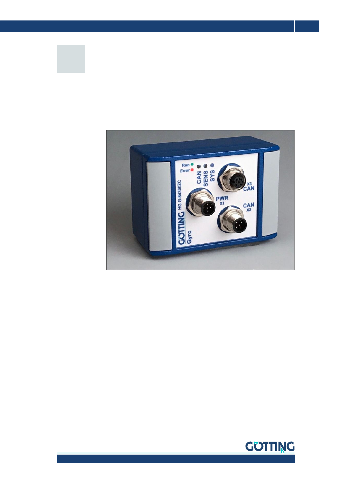
2 Introduction....................................................................................... 7
3 Hardware ........................................................................................... 8
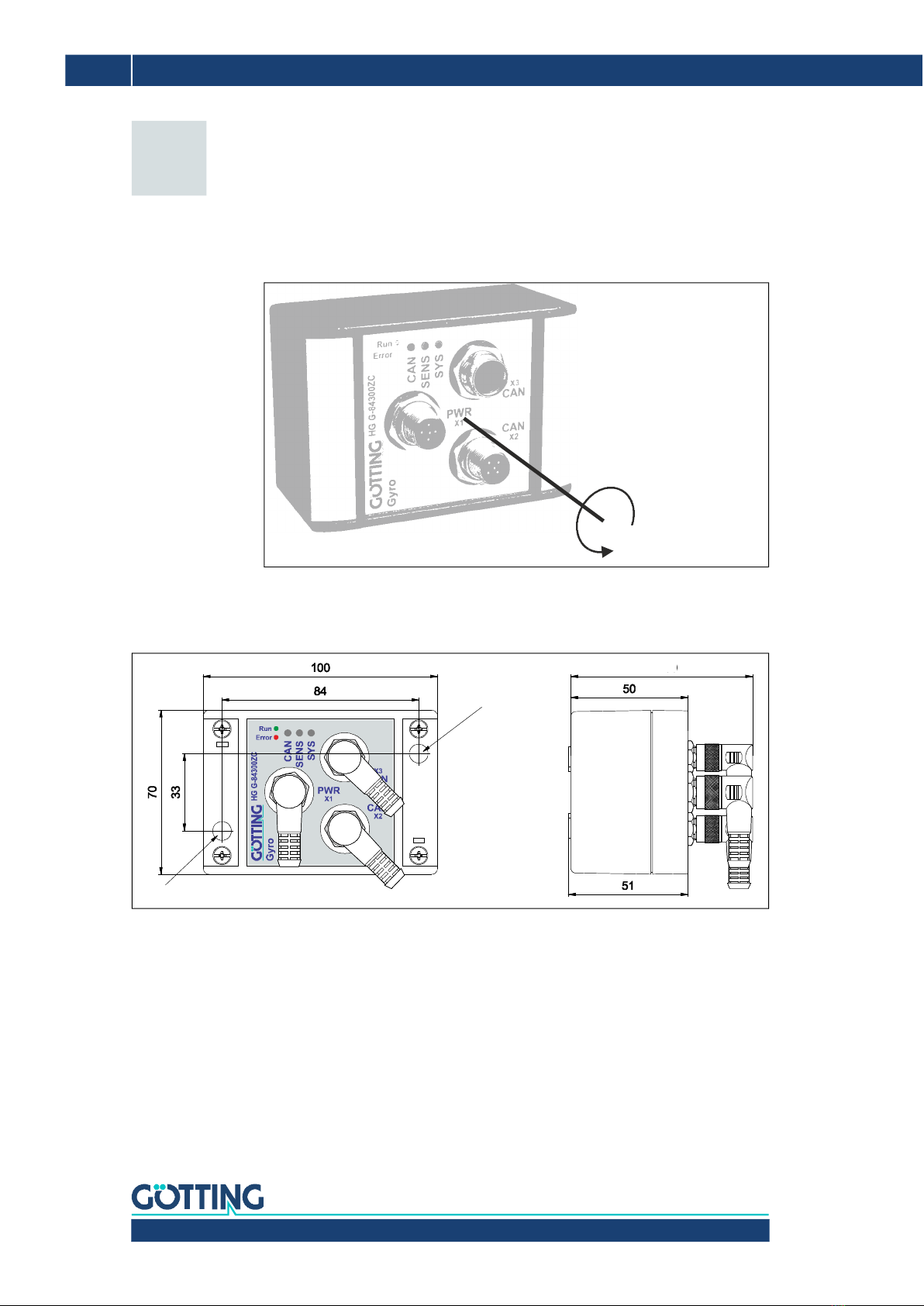
3.1 Alignment of the Measuring Axis..................................................................................... 8
3.2 Dimensions ............................................................................................................................. 8
3.3 Mounting ................................................................................................................................. 8
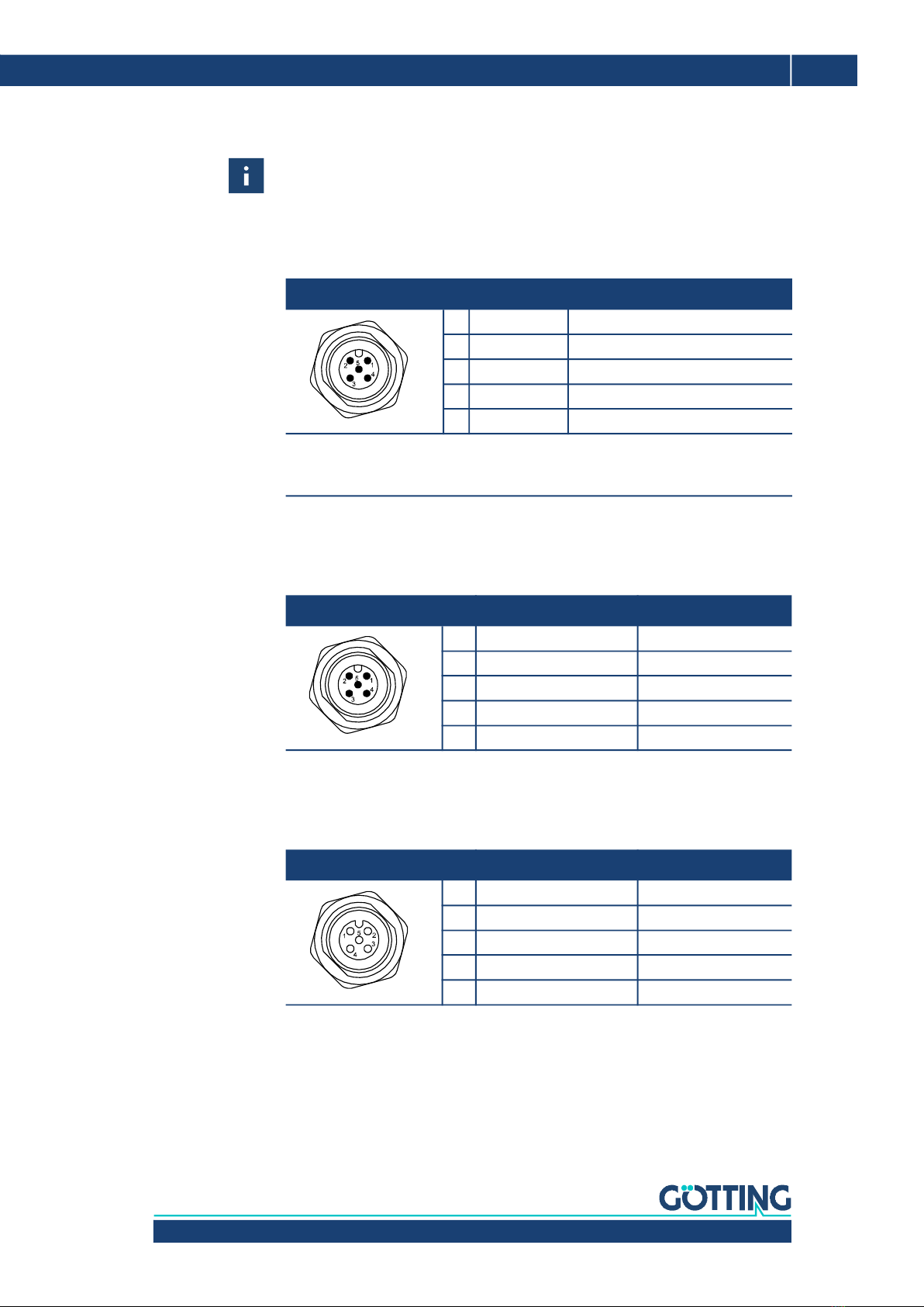
3.4 Pin Assignment...................................................................................................................... 9
3.4.1 X1 (PWR/USB) ................................................................................................................... 9
3.4.2 X2 (CAN).............................................................................................................................. 9
3.4.3 X3 (CAN).............................................................................................................................. 9
3.5 LEDs ........................................................................................................................................10
3.6 Error Messages ....................................................................................................................11
4 Drift Compensation / Angle Reset ................................................. 12
4.1 Drift Compensation ............................................................................................................12
4.2 Angle reset............................................................................................................................13
5 Configuration via USB .................................................................... 14
5.1 USB Interface .......................................................................................................................14
5.2 Terminal Program ...............................................................................................................14
5.3 Terminal Output In Monitor Mode ................................................................................. 15
5.3.1 Terminal Output for CAN Standard .......................................................................... 15
5.3.2 Terminal Output for CANopen®................................................................................. 16
5.4 Logging (CSV) ......................................................................................................................17
5.5 Firmware Update ................................................................................................................17
6 CAN Bus Interface .......................................................................... 20
6.1 Receiving Box ......................................................................................................................20
6.2 Transmitter Box...................................................................................................................21
7 CANopen® Interface ....................................................................... 22
7.1 Description of the Process Data Objects (PDOs) ......................................................22
7.1.1 Transmission Objects ....................................................................................................22
7.1.2 Reception Object ............................................................................................................23
7.2 Heartbeat...............................................................................................................................23
7.3 Description of the Service Data Objects (SDOs).......................................................24
7.4 Object Directory ..................................................................................................................24
7.4.1 Communication Specific Entries ...............................................................................24
7.4.2 Standardized Device Profile Range .......................................................................... 26
7.4.3 CANopen® Object Dictionary .....................................................................................26
7.4.3.1 Device Type .................................................................................................................26
7.4.3.2 Error Register ..............................................................................................................26
7.4.3.3 COB-ID SYNC message............................................................................................27
7.4.3.4 Device Name ............................................................................................................... 27
7.4.3.5 Hardware Version.......................................................................................................27
7.4.3.6 Software Version........................................................................................................27
7.4.3.7 Producer Heartbeat Time ........................................................................................27
7.4.3.8 Identity Object.............................................................................................................27
7.4.3.9 Receive PDO Parameter...........................................................................................28
7.4.3.10 Mapping RPDO_1.......................................................................................................28
7.4.3.11 Transmit PDO_1 Parameter....................................................................................28