Gottlieb PINK PANTHER 664 User manual

::r,l;1, 1 i.1?1. a
)-_=s
È---r:--L
Ë'a gl '+-/:9-
--q -zr ÿ
Lr'''--/
l---r-/,
à
EIi
-
--1
1
--.i
ffiottlieD
AMUSEMENT GAMES
165 W, Loke Street Norihloke, lL 60164
(312) 562. 7 400 letex 7 2. 8463
A Columbio Pictures lnduslries Compon, 6l

PINK PANTHER
INSTRUCTION MANUAL
TABLE OF CONTENTS
r. INSTRUCTTONS FOR PINK PANTHER (GAME #6641
II. INSTALLATION
III. GAME ADJUSTMENTS
IV. GAME OPERATION
V. BOOKKEEPING AND SELF-TEST
VI. OPTIONAL ELECTRO.MECHANICALCOIN COUNTERS
VII. SWITCH AND LAMP ASSIGNMENT
VI!I. PLAYBOARD INFORMATION
tX. P.C. BOARD CONNECTOR AND CABLE PLUG WIRE ASSIGNMENTS
X. WIRING AND SCHEMATIC DIAGRAMS
PINK PANTHER PROMS
GAME#6æ
ARE MARKED AS FOLLOWS:
GAME PROM 1 is 664/1
GAME PROM 2 IS NOT USED
SOUND PROM IS 664
INSERT PROMS WITH
INDENT NOTCH UP
CONTROL BOARD
#P803-D107-001
TM & O 1980 United Artists
ALL RIGHTS RESERVED

TOP ROLLOVERS
INSTRUCTIONS FOR PINK PANTHER (cAtrtE #6641
TOP POP BUMPERS
WHEN LIT: SCORE 5000 PTS. (3-BALL) OR so0o pTS. (S-BALL). LTGHT
CORRESPONDING BOTTOM ROLLOVER. LIGHT COR.
RESPONDING BLUE DIAMOND.
WHEN UNLIT: SCORE s00.
SEQUENCE COMPLETE LIGHTS EXTRA BALL. LAUNCH CAPTIVE BALLS
WHEN THIRD BALL HITS SWITCH.
SCORE 1000 PTS. (3-BALL) or 100 PTS. (S-BALL). ALTERNATE EXTRA BALL
LIGHT IN FIVE BALLONLY.
10 POINTSWITCHES SCORË 10 PTS.
AND BOTTOM
POP BUMPER
F
.L
;
!
t
I
!
,
I
I
;
Ë
È
*
t
!:
é
F:
E
BOTTOM
ROLLOVERS
BLACK DROP
TARGETS
WHITE DROP
ÏARGETS
1ST SPOT
TARGET
WHEN LIT: SCORE 5000 PTS.
ADD BLUE DIAMOND.
WHEN UNLIT: SCORE s00 PTS.
SCORE 5OO PTS.
SEQUENCE COMPLETE:
ADDS TO BLUE DUAMOND
PLAYFIELD
RESET BANK AND ADD BONUS. LIGHTS LEFT
HOLE FOR CAPTURE. AWARDS SPECIAL
WHEN L!T.
TOTAL WHEN MUIJIPLE BALLS ARE ON THE
WHEN LIT: 3000 PTS. AND ADD BONUS.
WHEN UNLIT: 500 PTS.
SEQUENCE COMPLETE: RESET BANK AND ADD BONUS. LIGHTS RIGHT
HOLE FOR CAPTURE.
WHEN LIT: SCORE 3000 PTS. AND ADD BONUS.
WHEN UNLIT: SCORE 500 PTS. AND LIcHT PINK. ADDS TO BLUE
DIAMOND TOTAL WHEN MULTIPLE BALLS ARE ON
PLAYFIELD.

SPOTTARGETS
LEFTCAPTIVE
HOLE
RIGHTCAPTIVE
HOLE
NONE LIT: SCORE 500 PTS. AND LIGHT PINK.
PINK LIT: SCORE 3000 PTS. AND LIGHT BLUE. TURN OFF PINK AND
ADD BONIJS.
BLUE LIT: SCORE 3000 PTS., LIGHT PINK, AND ADD BONUS.
BOTH LIT: COLLECT BONUS AND TURN OFF PINKAND BLUE.
sPoTS CORRESPONDTNG WH|TE DROP TAHGETS (2ND AND 3RD SPOT
TARGET). ADDS TO BLUE DIAMOND TOTAL DURING MULTIPLE BALL PLAY.
SCORE 5OOO PTS.
WHEN LIT: CAPTURE BALL AND RELEASE NEXT BALL TO SHOOTER.
SCORE 5OOO PTS.
WHEN LIT: CAPTURE BALLAND RELEASE BALLTO SHOOTER.
LOWER RIGHT HOLE SCORE 5OOO PTS. ADD A BLUE DIAMOND. AWARD EXTRA BALLWHEN LIT.
OUTHOLESWITCH COLLECTBONUSTIMESMULTIPLIER.
MULTIBALL UPON CAPTURING BALLS IN BOTH THE LEFT AND RIGHT HOLES, THE
CLOSUBE OF A TOP ROLLOVER WITH THE THIRD BALL WILL RELEASE
FIRST THE LEFT BALL, THEN THE RIGHT. AT THIS POINT ALL SPOT
TARGETS WILL HAVE ONLY THEIR BLUE DIAMONDS LIT. HITTING TI-IE
SPOT TARGETS WHILE IN THIS STATE WILL SCORE 3OOO PTS. AND ADD
BONUS AND ADD TO THE BLUE DIAMOND TOTAL SHOWN IN THE LIGHT.
BOX. HITTING ANY BLACK DROP TARGET WILL ALSO ADD TO THE BLUE
DIAMOND TOTAL. THE REST OF THE SWITCHES SCORE AS BEFORE
BUÏ NOW NO PINK LIGHTS CAN BE LIT. WHEN TWO BALLS HAVE
RETURNED TO THE OUTHOLE, THE GAME REVERTS BACK ÏO ORIGINAL
SCORING AND CONTROL.
AFTER COLLECTING BONUS, THE NUMBER OF BLUE DIAMONDS WON (lF
ANY) ON THAT BALLARE CHECKEDAGAINSTTHE PREVIOUS HIGH. IFTHE
PREVIOUS HIGH HAS BEEN EXCEEDED, THEN THE PLAYER IS AWARDED
A SPECIAL AND HIS TOTAL BECOMES THE NEW HIGH.
THE CURRENT BLUE DIAMOND TOTAL TO DATE IS STORED IN BOOK-
KEEPING. IT IS HELD AND SHOWN IN THE FIRST HIGH SCORE LEVEL
MEMORY IN THE UNIT§ AND TEN'S DIGIT POSITIONS. THIS IS STEP
11 IN THE TEST MODE. IT CAN BE ZEROED BY USING THE FRONT
DOOR SWITCH.
SWITCH #32 WILL CONTROL THE MAXIMUM BLUE DIAMOND TOTAL. AT
THE START OF A GAME, IF THE BLUE DIAMOND TOTAL IS AT THE
MAXIMUM, IT WILLAUTOMATICALLY BE RESETTO 18.
SWITCH #32 ON _ MAXIMUM TOTAL IS 50.
SWITCH #32 OFF _ MAXIMUM TOTAL IS 40.

SPECIAL
EXÏRA BALL
BONUS MULTIPLIER
HIGH GAME TO DATE
AWARDED 2 WAYS. DURING MULTI.BALL, EACH SPOTTARGETAND BLACK
TARGET HIT SCORES 1 DIAMOND. EXCEEDING "TOTAL TO BEAT" AWARDS
SPECIAL. ALSO, COMPLETING BLACK TARGET BANK AWARDS SPECIAL
WHEN LIT.
THE SPECIAL LIGHT WILL COME ON ONLY WHEN THERE HAVE BEEN
THREE BALLS RELEASED ON THE P]ÂYFIELD. IT WILL REMAIN ON FOR A
TIME DETERMINED BY SWITCH #31 OR UNTIL TWO BALLS HAVE LEFT
THE PLAYFIELD, WHICHEVER OCCURS FIRST.
WHEN LII WILL ALTERNATE OFF THE TOP POP BUMPERS DUR]NG FIVE
BALL PLAY.
EACH SPOT TARGET BECOMES A MULTIPLIER WHEN BOTH PINK AND
BLUE LIGHTS ARE LIT. AT THE END OF BALL PLAY BONUS TIMES MUL-
TIPLTER (ONE PLUS NUMBER OF MULTtPLIER).
IF THE HGTD SCOHE IS 99O,OOO OR GREATER AT THE START OF A GAME,
THEN IT WILL AUTOMATICALLY BE RESET TO THE PROM DEFAULT VALUE
oF HGTD (740,000).
II. INSTALLATION
To assemble the game, first bolt the legs to the cabinet. Feed the line cord through the slot provided in the
pedestal. Place the lightbox atop the pedestal and engage the holding brackets.
To remove glass, insert key and unlock. Lift glass up and swing bottom out. Loosen and lower the shipping
bracket at top center of lightbox insert panel. Lift panel up and then swing out. Secure lightbox to câ$inel
with the four bolts and washers provided.
Connect allcables and secure with cable ctamps provided. lnspect the following before plugging in the
line cord:
1 . Check that cables are clear of moving parts.
2. Look for any disconnected wires.
3. Check switches for loose solder or other foreign matter.
4. Be certain allfuses are firmly seated.
5. Check the transformers for foreign matter across the terminals.
6. Be sure that the transformer wiring corresponds to the supply voltage.
7. Check the setting of the tilt switch on the underside of the playfield. One blade of this switch is free-
floating with a weight on the end.
After.leveling the. machine, adjust the plum-bob tilt (on left side of cabinet near front door) to the
sensitivity desired.

III. GAME ADJUSTMENTS
A. CONTROL BOARD SWITCH ADJUSTMENTS
There are 32 switches on the control board which
permit adjustment of the game parameters. These
switches are contained in four packages of eight
switches each, as shown below:
S1_S8 s9- s1 6s17- S24 s25- S32
COIN CHUTE
SWITCHES ADJUSTilEilTS
S1 S2 S3 S4HChute
SWITCH l3-EXTRA CREDITS
ON . .. ... ... Addsgcreditstocentercoinchutesetting
OFF ........ Noeffect
NOTE: FOR GERMAN GAMES ONLy Switch .t3 adds g credits to
the right coin chute setting, when ON.
SWITCH laHOtN CHUTE CONTROL
ON ......... Leftand RightChutessame
OFF ........ Leftand Rightchutesseparate
NOTE: FOR GERMAN GAMES ONLY Switch 14 controts the left
and center coin chutes.
SWTCHES
15 I+MAXIMUICREDITS
oFF OFF 8
oFF oN ...... :.. :.::....::..::. ::::.:. ..... 10
ON OFF .. . .. .. . ... 15
oN oN .. . ..... .... 2s
swtTcH l7-BALLS PEH GAME
oN ... g
oFF .. 5
swlTcH I8-MATCH FEATURE
oN.... .......... oN
oFF... ......... oFF
SWITCH 19
-REpLAy
LtMtT
ON ... ..... . Limitseach playertoone replay pergame
OFF ........ Noreplaytimit
SWITCH 2O-NOVELTY MODE
ON ......... Ptayfietd SPECTAL and EXTRA BALL fea-
tures award 50,000 points and 5 knocks.
High score, high game to date, and match
features disabled.
OFF . .. . .. . . Normal game mode
NOTE: SWITCH 20 overrides SWTTCH 21.
SW]TCHâ MODE
ON ......... ExtraBall
OFF .. ... ... Reptay
NOTE: lF SWITCH 21 is ON, the high game to date and match
awards are disabled. -
SWITCH 22
-PLAYFTELD
SPECIAL
ON ......... AwardsExtraBall
OFF ........ AwardsSpecial
SWITCHES H|GH GAME TO DATE
23 24
OFF OFF .... Notdisplayed-noaward
OFF ON ..... Displayed-noaward
gry gFF .. Disptayed-awards2reptays
ON ON ..... Displayed-awards3replaÿs
SwlTCH 2S-SOUND WHEN SCORTNG?
oN ... . ... .. ... . Yes
OFF ... .......... No
SWITCH 2Ç-REpLAy BUTTON TUNE?
oN...
OFF ... .. ..... .. . yes
swlTcH2z """""...èô*r*,r"rtr"Ii
ON ... .. .. .. ,.. . yes
oFF ... .......... No
SWTTCH 28#REDITS DtSpLAyED?
ON ... . .. . .... .. yes
oFF ... .......... No
swrTcH29 TILT PENALTY
ON ......... Balt inptayonly
OFF......... Gameover
swtTcH 3o-ATTRACT FEATURES
oN.... .......... oN
OFF..: ......... OFF
swrTcH3l
ON.... ....... Liberal
oFF . .. conservative
swtTcH32
ON ... . Conservative
oFF... ....... Liberal
s5 s6 57 S8_Right chure
Sg S10 S1 1 Sl2fleriIerChute
NOTE: FOR GERMAN GAMES ONLy switches S5-SB adjustttre
center chute and switches S9-S12 adjust the right chute.
cotNs/cREIXTS
oFF OFF OFF OFF. . -.. - 1/1
-oFF OFF OFF ON ....... 1/2
oFF OFF ON OFF. . . ... 1/s
oFF OFF ON ON.... ... 1/4
oFF ON OFF ON ....... 1/6
' ON OFF OFF ON..........., ...2/1*
ON OFF ON OFF. . . . .. z/2.
oN oFF ON ON.. .. ... 2/g,
' ON ON OFF OFF ...... 2/4*
oN oN oFF ON . ...... 2/5*
ON ON ON OFF . . .. . 1/1 and2/3
oN oN ON ON.. . . ... s/1*
-NO CREDITS UNTIL LAST COIN IS INSERTED.

tv.
LI BERAL.CONSERVATIVE ADJUSTMENT
Switch 31 in the liberal position allows plaÿield specialto be on 20% longer than conservative position.
Switch 32 controls the maximum Blue Diamond Total. The conservative position sets maximum to 50.
The liberal position sets maximum to 40. .
B. ELECTRONIC SOUND ADJUSTMENTS
There are two switches on the SOUND BOARD which allowvariation:
swrTcH s1
MUST REMAIN IN OFF POSITION
swrTcH s2
oFF ...
oN .... NO ATTRACTTUNE
ATTRACTTUNE PLAYED EVERY6 MINUTES
The volume control is on the bottom panel in the cabinet and is accessible from the front door opening.
Switch 53 is a test switoh. Pushing 33 will generate a short tune if switches 51 and S2 are in opposite
states. No tune will be played if switches 51 and 52 are in the same state. This enables the oper-
ator to test the condition of both switches and to verify that the audio-output portion of the sound
board is functional.
C. POST ADJUSTMENT SEE PAGE 9.
GAME OPERATION
!Vi!n tne line cord unplugged drop a coin into one of the chutes. lt should be rejected. Plug the line cord
ONLY into a properly grounded 3-wire receptacle of the correct voltage. Turn on ihe game b-y pressing the
main switch located on the cabinet bottom near the front right corner.
After a five second delay the relays will pulse and the score displays will light and show all zeros. The credit
display will show the number of credits remaining and the ball in play display will be blank. lf the credits fail
to light, turn off the game and inspect the front door slam switch. lt is normàlly closed.
Five seconds after the score displays light, they will flash the High Game to Date score for one second. This
cycle continues untilthe game is started. A number of playfield lights controlled by the MPU will be flashed
to create an attract mode.
lnsert coins into each chute and note that the correct number of credits are added on the credit display
according to the information on the coin entrance plate. Press the ieplay button to reset the game; the'bail
should now be at the shooter. (Note: All balls must be in trough to start !ame.) The first playù score reads
zero and flashes, indicatingthat that player is now scoring. the other player itisplays aie btanf and a one
appears on the ballin play display. Additional players are indicated by azero shôwing in each correspond-
ing player display. After the maximum number of players has been added, or when thé credit display reads
zero, the replay.button has no effect.
Additional players can be added at any time the first ball is still in play.
When the ball enters the outhole the bonus is scored, the ball is kicked to the shooter, and the display of the
player now scoring begins to flash and continues to flash until a score is made. When the ShootAgain light
is lit neither the player designation (flashing display) nor the ball in play display changes wfreÀtne nalt
enters the outhole. Oàly one extra ball per ball in play can be given.
The number of balls per game is adjustable. When the last ball enters the outhole, the Game Over and
Number to Match lights come on. A random number appears in the ball in play display and if this number
matches the last two digits in any player's score a replay is awarded. At this time a High êame to Date score
is periodically flashed in all player displays. When a score higher than this is achieveà, an award dependent
on switches 23 and 24 is given.
Tilting the game results in a penalty depending on the setting of switch 29. There is a normally closed
switch on the front door. lf this switch opens from pounding the front door, the entire game is ended. The
Game Over light comes on and for three seconds the entirè switch matrix is inactive.
BOOKKEEPING AND SELF.TEST
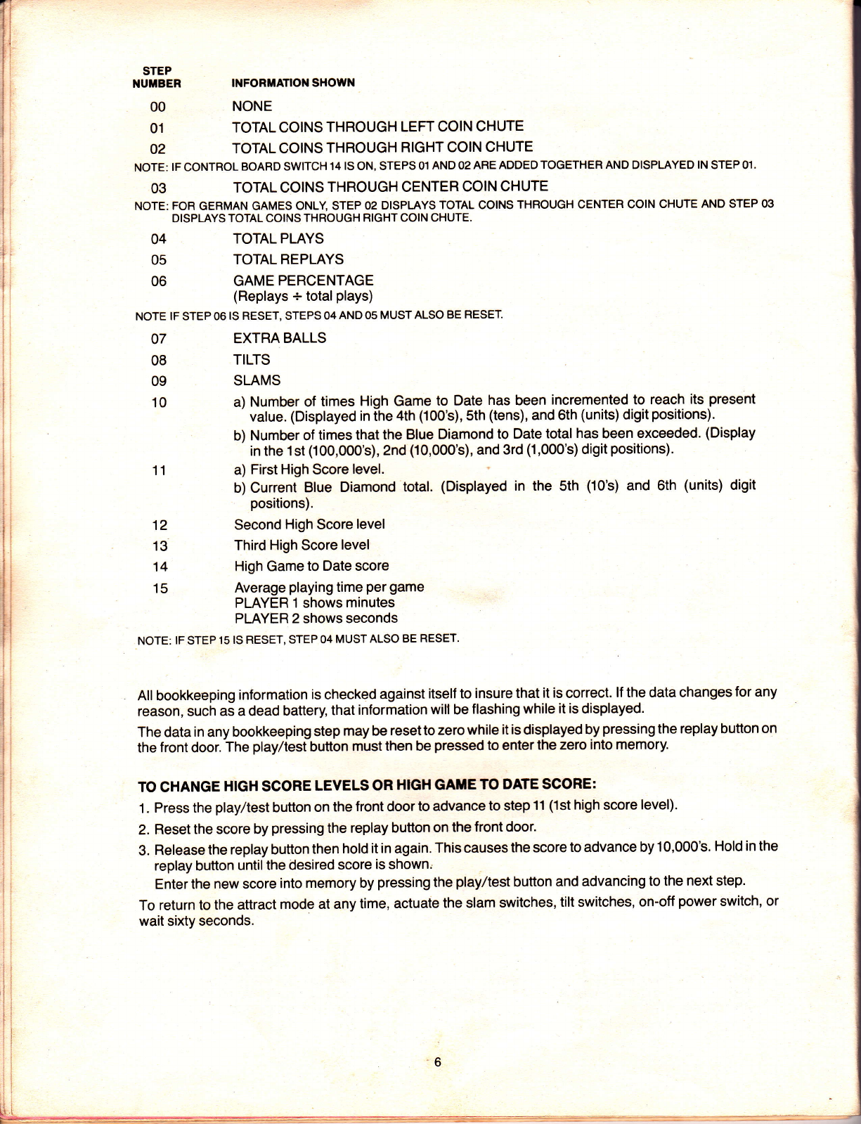
T.he circuitry in this game helps the operator perform many bookkeeping functions. The information is
shown one step at a time on the first player score display while the step number is shown in the credit
display. Pressing the play/test button on the front door begins the bookkeeping and advances it to the next
step each time the button is pressed. lf the button is notpressed within sixtÿ seconds of each step, the
game returns to the attract mode.
V.
ts--*..'.

STEP
1'UTBER
00
01
02
INFORTIATIOi' SHOIYN
NONE
TOTAL COINS THROUGH LEFT COIN CHUTE
TOTAL COINS THROUGH RIGHT COIN CHUTE
NOTE: IF CONTROL BOARD SWITCH 14 IS ON, STEPS O1 AND 02 AHE ADDED TOGETHER AND DISPLAYED IN STEP 01.
03 TOTAL COTNS THROUGH CENTEH COIN CHUTE
NQTE: FOR GERMAN GAMES ONLY STEP 02 DISPLAYS TOTAL COINS THROUGH CENTER COIN CHUTE AND STEP 03
DISPLAYS TOTAL COINS THROUGH RIGHT COIN CHUTE.
TOTAL PLAYS
TOTAL REPLAYS
GAME PERCENTAGE
(Replays + totalplays)
NOTE IF STEP 06 IS RESET, STEPS 04 AND 05 MUST ALSO BE RESEÎ
EXTRA BALLS
TILTS
SLAMS
a) Number of times High Game to Date has been incremented to reach its.present
value. (Displayed in the 4th (100's), Sth (tens), and 6th (units) digit positions).
b) Number of times that the Blue Diamond to Date total has been exceeded. (Display
in the 1st (100,0O0's),2nd (10,0O0's), and 3rd (1,000's) digit positions)'
a) First High Score level.
b) Current Blue Diamond total. (Displayed in the Sth (10's) and 6th (units) digit
positions).
Second High Score level
Third High Score level
High Game to Date score
Average playing time per game
PLAYEH 1 shows minutes
PLAYER 2 shows seconds
NOTE: lF STEP 15 lS RESET, STEP 04 MUST ALSO BE RESET.
All bookkeeping information is checked against itself to insure that it is correct. lf the data changes for any
reason, such ai a dead battery, that information will be flashing while it is displayed.
The data in any bookkeeping step may be reset to zero while it is displayed by pressing the replay button on
the front door. The play/test button must then be pressed to enter the zero into memory.
TO CHANGE HIGH SCORE LEVELS OR HIG}I GATE TO DATE SCORE:
1 . Press the play/test button on the front door to advance to step 11 (lst high score level).
2. Reset the score by pressing the replay button on the front door.
3. Release the replay button then hold it in again. This causes the score to advance by 10,000's. Hold in the
replay button until the desired score is shown.
Enter the new score into memory by pressing the play/test button and advancing to the next step.
To return to the attract mode at any time, actuate the slam switches, tilt switches, on-off power switch, or
wait sixty seconds.
04
05
06
07
08
09
10
11
12
13
14
15

SELF.TEST FEATURES:
The self-test routine begins with STEI_1p. To bypass the bookkeeping functions and advance direcily to
self-test, press the Replay button in STÊP 00.
STEP
NUMBER
16 LAMP ÎEST
Relays and coin lockout coil are pulsed, then all controlled lamps are turned on in sequence.
17 SOLENOID TEST
Each controlled solenoid is pulsed while its number æpears on the status display.
SOLENOID ASSIGNiIENIS
NUUBER FUNCTION
1 Lower Right Hote Kicker
2 Center DropTarget Bank
3 Left Coin Chute counterÊ
4 Flight Coin Chute counter.
5 Left DropTarget Bank
6 Trough Switch
7 Center Coin Chute counter*
8 Knocker
9 Outhole
'Coin counters are optional and are t{OT pulsed during SOLENOID TEST.
NOTE: FOR GERMAN GAMES ONLY SOLENOID #4 is assigned to the centercoin chute counter and SOLENOID #7 is assigned
to the right coin chute counter.
18 SWITCH TEST
All switches on the switch rnatrix are inspected. lf all switches are open, 99 is displayed
on the status display. lf one or more switches are closed, their numbers will appear'onihe
status displays.
CAUTION: TURN POWER OFF BEFORË MAKING ANY STIVITCH ADJUSTMENTS!
19 DISPLAY ÎEST
Each digit of each display is turned on individually and all numbers 0-g are sequenced.
20 MEIIORYTEST
Each control board mêmory device is ihspected. Any defective devices are indicated by part
number on the PHYER 1 score display. lf all memory devices are okay, 9g is displayôd on
' the status display.
Any of the tests in steps 16 through 2O may be repeated any number of times by pressing thê replay button
immediately afterthe test is completed.
VI. OPTIONALELECTRO.MECHAHICALCOINCOUNTEBS
Electro-mechanical coin counters may be installed on the bottom board, if desired. Direcfly behind
the seven position fuse block, solder lugs are provided which will connect the counters to ihe elec-
tronic circuitry.
1. Position the counter and secure it to the bottom board. Mounting holes are spotted in the bottom board
for rnost standard 24 vollcounters.
2. CAUTION: A 1N4004 diode must be connected across each counterwith the cathode endconnected to
the solder lug with the RED-BLACK-BLACK wire.
3. Connect one counter lead to each of the two solder lugs provided for each counter.
4. The counter should increment once when the respective coin chute switch is closed.
Er-=

F.
VI!. SWITCH MATRIX AND LAMP LOCATION ASSIGNMENT
SWITCH MATRIX AND LAMP LOCATION
sw. rATRlx
NUIIBER
00
01
.02
03
.t0
11
12
.13
20
21
22
23
30
31
32
STYITCH ASSIGXXIENÎ
#1 Whit€Target
#5 WhiteTarget
#1 Top Rollover
Hight Return Rollover
#2 WhiteTarget
#6WhiteTarçt
#2 Top Rollover
Extra Ball Hole Sw.
#3 WhiteTârget
#7 WhiteTarget
#3 Top Rollover
Top Pop Bumper (3)
#4 WhiteTarget
#SwhiteTarget
#4 Top Rollover
#1 Black DropTarget
#9 WhiteTarget
Left Return Roltover
Lett Captive Hole
#2 Black DropTarget
#1 white DropTarget
Right Captive Hole
#3 Black DropTarget
#2 White DropTarget
Left Outside Rollover
Outhole
#4 Black DroPTarget
#3 White DropTarget
BightOutside Rollover
Trough
#4WhiteTarget
#5 WhiteTarget
#6 WhitêTarget
#7 WhitêTarget
#8 WhiteTarget
#9WhiteTarget
Lett Captivê Hole
Extra Ball
Special
Right Captive
1 Carat
2 Carat
3 Carat
4 carât
5 Carat
6 Carat
7 Caral
I Carat
I Carat
10 Carat
20 Carat
Left Outside Rollover
Lett Return Rollover
Right Return Rollover
Right Outside Rollover
#1 Top Rollover
#2 Top Rollover
#3 Top Rollover
#4 Top Rollover
*_7t
rÀ ,/\
ïu
ï
t
@
ô
rltl
l
I
È
t
r
r:
F
i
fBonom Pop Bump€r
rr -1 10 Point sÛitchss
40
41
42
43
50
51
53
60
61
62
63
70
71
72
73
123
w4
L25
L26
L27
128
L29
130
131
L32
133
L34
135
136
137
138
139
L40
L41
L42
143
L44
L45
L46
L47
L48
149
L50
L51
LATP
HUTBËR LATPA§§IGNTENÎ
0 Game Over Relay (Located Under
Playlield)
1 Tilt Relay (Locatêd Under
Playlield)
2 Coin Lockout Coil (Located On
Front Dooo
3 Same Player Shoots Again
(Light Box ând Playfield)
10 High Game To Date t Located
11 Game Over J in Lightbox
L12 1 x Multipliêr
L13 1 x Multiplier
L14 1 x Multiplier
L15 1 x Multipliêr
L16 1 x Multiplier
L17 1 x Multiplier
L18 1 x Multiplier
L19 1 x Multiplier
t#l WhiteTaroet
Lzu
-[*t white Dro-pÎarget
f #2 WhiteTaroet
ut
-t#2 white Dro,-pTarçt
f#3 WhiteTaroet
*' -1 *g white oro'p Target

VIII. PLAYBOARO INFORMATION
oo
"n"( "J,"[l,(. )
U\-*JUI I
o vo ^\ÿ
Oelv
uo
o
ô
"n(\o&
"lJ I l"l,.l a
^t-b-, ^[
o^\
Orl \
//\v (r
\ u^o \
) uo\
I / \ 3'
./ (J z--r ,
\/
oâ
o-
^o
,---.( ) -
(., -
la
o
o
8
o
a
o
EE
PLAYBOARD INFORMATION
RUBBER RINGS
A-A-10217 s/rc (11)
B - A-10218 3h (1)
c - A-10219 1u (3)
O-A-10220 1V2' (2)
E-A-10221 z',(1)
F-A-10222 zYz' (2)
G-A-10223 3u (2)
H - A-13151 (3)
r-A-15705 (10)
PARTS LIST
1. A-19645 BallGuide Right.
2. A-19æ6 BallGuide Left.
3. D-2O478 Plastic Shield Set.
4. Blue Pop Bumper A-2O577 and A-20586
Cap in Blue. (2)
5. Blue Pop Bumper A-20577 and A-20588
Cap in Blue. (1)
6. Blue Pop Bumper A-2O577 and A-20590
7.
8.
9.
10.
11.
12.
13.
14.
15.
16.
17.
18.
19.
20.
21.
22.
23.
24.
25.
26.
27.
28.
Cap in Blue. (1)
Blue Pop Bumper Skirt. (4)
A-2O522 PlasticTarget in Pink. (9)
A-2O524 Black DropTarget in Blue. (4)
A-20647 White DropTarget in Pink. (3)
A-4831 BallGuide Rail. (4)
A-4832 BallGuide Rail. (2)
A-4833 BallGuide Rail.
A-6931 BallGuide Rail. (4)
A-13798 BallSnubber Rail. (2)
A-1 6991 Ball Guide Rail.
A-17650 Ball Guide Rail. (2)
A-18070 BallGuide Rail. (6)
A-1 8563 Ball Guide Rail.
A-1 9995 Ball Guide Rail.
A-19996 Ball Guide Rail.
A-1 4389 Metal Flat Rail.
C-20453 Metal Flat Rail.
A-15636 Left Kicking Rubber.
A-15638 Right Kicking Rubber.
A-17300 Roll Under Gate.
C-13150 Jumbo White Flipper. (3)
A-20362 Flat RailClip. (2)
C-11561 Clear 1" High Post. (4Q):
C-1 1562 Clear 13/ro" High Post;,{2,}
CON. =CONSERVATIVE.
LlB. =LIBERAL.
+'---

tx. P.C. BOARD BOIIHECTOR AT.ID CABLE PLUG WIRE ASSIGNTIENTS
The followirts lists provide wire color and function inlormation for each wire of each connector in the game.
Wire colOrs are shOrn as numbers. USe the chart below to corwert to colors.
0 Black
1 Brown
2 Red
3 Orange
4 Yellow
5 Green
6 Blue
7 Purple
I Slate
I White
For erample, 688 is a BLUE-SLATE-SLATE striped wirc.
Printed Circuit Board connectors are sholn as AX-JX.
uqe the followins chart to determine i"j#i il::j board appries :
îC PowerSuPPlY
4q QriverBoard
A4 Sære DisPlaYs (4)
AS Status DisolaY
A6 SoundBoard
AB PoPBumPerDriverBoard
For example, ASJ3 isconrector.tgtrt Üte drtverboard
There are eight male/female cable connectors in tàe game. Ihese are shown as A7-JXIPX.
- TherE are three male/fenrale cableconnectors to interænnect the status display on the playboard to the
control board in the lightbox. They are listed on page 14 as AI&JVPX'
. '.:' I ..i '

Plt{
1
2
3
4
5
1
2
3
4
5
6
7
I
PIN COLOR
A1..rl
WIRE
COLOR
*688
*688
*54
'54 A1\,2
wlRE
coLon
300
311
322
333
344
3s5
366
377
600
611
622
633
644
655
666
677
800
811
822
833
8M'
855
866
877
A1-.t3
WIRE
400
411
422
433
444
455
466
477
700
7'.t1
722
733
744
755
FUracTloN
+5VDC
+5VDC
SPARE
GROUND
GROUND
FUXCTIO|{
AA
bA
CA
dA
EA
fA
gA
hA
AB
bB
CB
dB
EB
fB
gB
hB
ac
bc
cc
dc
ec
fc
gc
hc
FUt{CTrOt{
D1
D2
D3
D4
D5
D6
D7
D8
D9
D1o
Dl1
012
D13
Dl3
Dl5
Dl6
SPARE
At-.r4
WIRE
COLOR
*s
'688
I
I
I
9
_
:
:
I
I
9
i
I
I
I
I
9
9
I
I
I
I
9
I
I
9
i
FUNCTION
GROUND
+5VDC
DS2
LD3
LD4
LDz
LD1
SPARE
SPARE
SPARE
SPARE
SPARE
SPARE
SPARE
SPARE
SPABE
SPARE
KEY
SPARE
SPARE
KNOCKER
3RD COUNTER
2ND COUNTER'
lSTCOUNTER
SPARE
SPABE
DS1
DS4
DS3
DS6
DS5
DS8
DS7
DSlO
DS9
DSl1
DS12
SOLENOID 5
SOLENOID 1
OUTHOLE
SOLENOID 6
(KEY)
SPARE
SOLENOID 2
SOUND 8
SOUND 4
SOUND 2
SOUND 1
Ptx
1
2
3
4
5
6
7
I
I
10
11
12
13
14
15
16
17
18
19
æ
21
22
23
24
I
10
11
12
13
14
15
16
17
P|lt
1
2
3
4
5
6
7
I
9
10
't1
12
13
14
15
16
17
18
19
20
21
22
23
24
A
B
c
D
E
F
H
J
K
L
M
N
P
R
S
T
U
V
W
x
Y
z
À
6
;
I
9
I
I
766
777
ALL W|RES #22GAVGE UNLESS SPECTFIED. (18 GA.)
+
11

PIN
1
2
3
4
5
6
7
8
I
10
PIN
1
2
3
4
5
6
7
I
I
10
11
12
13
14
15
16
17
18
19
WtRE
COLOR
677
400
411
422
433
*444
455
666
477
700
A1.J6
WIRE
COLOR
400
411
422
433
444
455
466
477
I
611
622
633
yo
FUNCTION
RETURN 7
STROBE O
STROBE 1
STROBE 2
STROBE3
STROBE 4
STROBE 5
RETURN 6
STROBE 7
SLAM SW.
FUNCTION
STROBE O
STROBE 1
STROBE 2
STROBE 3
STROBE 4
STROBE 5
STROBE 6
STROBE 7
GROUND
RETURN O
RETURN 1
RETURN 2
RETURN 3
RETURN 4
SPARE
SPARE
RETURN 7
+5VDC
SPARE
42.J3
WIRE
COLOR
044
055
54
54
688
A3..Jl
WIRE
COLOR
*54
*688
I
9
I
9
I
FUNCTION
+60vDc
(KEY)
+42VDC
GROUND
GROUND
SPARE
+5VDC
FUNCT|ON
GROUND
+5VDC
DS2
LD3
LD4
LD2
LD1
SPARE
SPARE
SPARE
SPARE
SPARE
SPARE
SPARE
SPARE
SPARE
SPARE
SPARE
(KEY)
SPARE
KNOCKER
3RD COUNÏER
2ND COUNTER
1 ST COUNTER
SPARE
SPARE
DS1
DS4
DS3
DS6
DS5
DS8
DS7
DSlO
DS9
DS1 1
DS12
SOLENOID 5
SOLENOID 1
OUTHOLE
SOLENOID 6
SPARE
(KEY)
SOLENOID 2
SOUND B
SOUND 4
SOUND 2
SOUND 1
PIN
1
2
3
4
5
6
7
I
I
o
o
;
9
9
I
9
PIN
1
2
3
4
5
6
7
I
I
PIN
1
2
3
4
5
6
A2*rI
WIRE
COLOR FUNCTION
(#16GA) 12VDC
200
(#16GA)
PIN
1
2
3
4
5
6
7
8
I
10
11
12
13
14
15
16
17
18
19
20
21
22
23
24
A
B
c
D
E
F
H
J
K
L
M
N
P
R
S
T
U
V
W
x
Y
z
À
B
;
I
I
9
I
9
9
I
9
9
I
I
I
9
I
v
688
166
100
1't1
133
GROUND
SPARE
(KEY)
+5VDC
+SVDC offset
6OVAC
6OVAC RETURN
+8VDC offset
A,2.J2
WIRE
COLOH FUNCTION
*688 +sVDC
*688 +sVDC
*54 GROUND
*54 GROUND
(KEY)
SPARE
ALLWIRES #zzGAUGÉ.
UNLESS SPECIFIED- (18 GA)
12

PIN
1
2
3
4
5
6
7
I
I
10
PIN
1
2
3
4
5
6
7
8
I
10
11
12
13
14
15
16
17
18
19
20
21
22
23
24
25
A
B
c
D
E
F
H
J
K
L
M
N
P
R
A3-.r2
WIRE
COLOB
588
500
511
533
522
*54
577
566
555
544A3.J3
WIRE
COLOR
777
755
744,
544
555
577
344
355
377
366
144
155
177
166
A3d3 continued
W!RE
COLOR FUNCTION
FUNCTION
SHOOTAGAIN LAMP
PLAYER 1 LAMP
PLAYER2 LAMP
PLAYER 4 LAMP
PLAYER3 LAMP
GROUND
HIGH GAME TO DATE LAMP
GAME OVER LAMP
L9
L8
FUNCTION
SPARE
L43
L4'.l
L40
L32
133
135
KEY
L24
L25
L27
L26
L16
L17
L19
L18
) Hr"
Ptt
S
T
U
V
w
x
Y
Z
A
E
c
PIN
1
2
3
4
5
6
7
I
9
10
11
12
13
14
15
'il
766
5æ
5ۃl
511
5(n
m
277
588
722
711
744
888
(16GA) 54 GROUND (128-135)
GROUND (140-143)
L42
L30
L31
L29
t28
GAMEOVER RELAY
TILTRELAY
SHOOTAGAIN LAMP
SPARE
SOUND 2
SOUND 1
SOUND 8
KNOCKER
(16G4)S GROUND (112-L1e)
A3-J4
U'IRE
coloR Fut{cTroil
700 L36
711 L37
733 L39
722 138
*54 GROUND (L36-139)
*2',t1 SOLENOID 5
*266 SOLENOID 1
*244 OUTHOLE (SOL.9)
*54 GROUND (SOL. 1, 9)
*s4 GROUND (SOL.2)
*s4 GROUND (SOL.6)
*233 SOLENOID 6
*200 SoLENOID 2
*54 GROUND (SOL.5)
SPARE
A3.J5
WIRE
OOLOR FUNGTION
733 SOUND4
877 COIN LOCKOUTCOIL
54 GROUND (KNOCKER)
(16GA) 54 GROUND (L20-27)
322 t22
333 L23
311 121
300 L20
122
133
111
100
1',
566
ess
Ll4
Ll5
L13
L12
SPARE
SPARE
GROUND (144-151)
L44
SPARE
L45
SPARE
KEY
134
SPARE
L47
SPARE
146
150
PIN
1
2
3
4
5
6
7
I
PIN
1
2
3
4
A3.J6
WIRE
COLOR FUNCTION
633 2NDCOUNTER
644 3RDCOUNTER
655 lSTCOUNTER
54 GROUND
822
866
ALL WIRES #22GAUGE UNLESS SPECIFIED* (18 GA.)
13

w
144-.J1
WIRE
COLOR
455
444
433
422
411
400
377
366
355
344
333
322
311
300
122
144
o44
54
2A4.11
WIRE
COLOR
733
722
711
700
477
466
377
366
355
344
333
322
311
300
122
144
o:o
54
344-J1
WIRE
COLOR
455
444
433
422
411
400
677
666
655
344{l continued
PIN
1
2
3
4
5
6
7
I
I
10
11
12
13
14
15
16
17
18
19
FUNCTION
D6
D5
D4
D3
D2
D1
hA
gA
fA
CA
dA
CA
bA
AA
5VAC
5VAC RETURN
+60vDc
SPARE
GROUND
FlrilCTloll
tl2
Dl1
D10
D9
D8
D7
hA
gA
fA
EA
dA
CA
bA
AA
5VAC
sVAC RETURN
+60vDc
SPARE
GROUND
FUNCTION
D6
D5
ù4
D3
D2
D1
hB
gB
fB
wlRE
COLOR
644
633
622
611
600
't22
1M
044
54
4A4-J1
WIRE
COLOR
733
722
711
700
477
466
677
666
655
644
6*l
622
611
600
122
144
044
54
544-.rl
WIRE
COLOR
455
yo
411
400
822
81I
877
866
8s5
844
833
155
't77
05s
-
FUNCNON
EB
dB
CB
bB
AB
5VAC
5VAC RETURN
+6OVDC
SPARE
GROUND
PIN
,10
11
12
13
14
15
16
17
18
19
PIN
1
2
3
4
5
6
7
I
I
10
11
12
13
14
15
16
17
18
19
PIN
1
2
3
4
5
6
7
I
I
10
11
12
13
14
15
16
17
18
19
FUNCTION
P.12
D11
D10
D9
D8
d7
hB
gB
fB
EB
dB
CB
bB
AB
5VAC
5VAC RËTURN
+60vDc
SPARE
GROUND
SVAC RETURN
+60vDc
SPARE
GROUND
PIN
1
2
3
4
5
6
7
I
I
PlN
1
2
3
4
5
6
7
I
I
10
11
12
13
14
15
16
17
18
19
FUNCTION
D6
D5
SPARE
SPARE
D2
D1
hC
gC
fC
eC
dc
cC
bc
aC
SVAC
ALLWIRES #22GAUGE UNLESS SPEOIFIED. (18 GA.)
14

45.J1
WIRE,
COLOB
777
766
755
744
822
811
877
866
855
844
833
800
155
177
055
688
s4
A7-,r2/P2
WRE
COLOR
Pll'l
1
2
3
,4
5
6
7
8
9
10
11
12
13
14
15
16
17
18
19
FUNCTION
SPARE
SPARE
D16
D15
D14
Dls
cc
bc
hc
gc
fc
ec
dc
ac
SVAC
3VAC RETURN
+42VOC
+5VDC
GROUNE
RETURN 7
STROBE O
STROBE 1
STROBE 2
STROBE 3
STROBE 4
STROBE 5
SPARE
SPARE
ANT|-CHEATSW. (SLAM)
ANTr-CHEATSW. (GND)
EARTH GROUND
1 *066
2 *æ0
3 '055
4 '3gg
5 222
6 877
FU}ICTION
COIN CHUTE LIGHTS
COIN CHUTE LIGHTS RETURN
LEFT FLIPPER SW]TCH
FLIPPER SWITCH RETURN
+24VDC
COIN LOCKOUT
FUXCNON
5VAC
sVAC RETURN
3VAC
3VAC RETURN
LAMPGROUND
SPARE
PIN
1
2
3
4
5
6
7
8
I
A7-.8/n
WRE
COLOR
*122
'144
155
177
*54
PIN
1
2
3
4
5
6
7
I
I
10
11
12
PIN
1
2
3
4
5
6
7
B
I
10
11
12
A6-J1
WIRE
COLOR FUNCTION
200
333
344
688
54
011
711
722
733
744
+12VDC
SPARE
AC
AC RETURN
+5VDC
GROUND
SPEAKER OUTPUT
SOUND 1
SOUND2
SPARE
SOUND4
SOUNDS
*54
*54
*54
*54
*54
*54
*54
*54
*54
*54
'1
PIN
1
2
3
4
5
6
7
I
I
10
11
12
1
2
3
4
5
6
7
I
9
10
't1
12
13
't4
15
(16GA) 077 6.3VAC
(16G4) 000 6.3VAC RETURN
*255
A7-J4/P4
WIRE
COLOR
^7-J5/P5
wlRE
côlôn FUNcroN
(16GA) 25s +6VDC
(16GA)54 GROUND
(16GA) 54 GROUND
(16GA) 54 GROUND
(16G4) 54 GROUND
(16GA) 222 +24VDC
+6VDC
FUNCTION
GROUND
GROUND
GROUND
GROUND
GROUND
GROUND
GROUND
GROUND
GROUND
GROUND
GROUND
SPARE
A7-t1/P1
WIRE
COLOR' . FUNCTION
677
500
511
533
522
544
555
700
9
*54
*388
*388
*055
*o44
(16GA) 066 6.3VAC
(16G4) 000 6.3VAC RETURN
FLIPPER SW. RETURN
FLIPPER S\It/. RETURN
LEFT FLIPPER SWITCH
RIGHT FLIPPER SWITCH
25VAC
2sVAC
*277
*288
ALL WIRES #22GAUGÊ. UNLESS SPEC|F|ED* (18 cA.)
(16GA)366 +38VDC

PIN
1
2
3
4
5
6
PIN
1
2
3
4
PIN
1
2
3
4
5
6
a22
688
o
PIN
1
2
3
4
PIN
1
2
3
4
PIN
1
2
3
4
5
6
PIN
1
2
3
4
5
6
PIN
1
2
3
4
5
6
A7-.r6lP6
WIRE
COLOF
o22
544
5ss
A7-J8/P8
WIRE
COLOR
o22
*54
*54
1A8-J1
WIRE
COLOR
'1 88
*54
477
688
I248{1
WFE
COLOR
*489
*54
011
688
I3A8-J1
WIRE
COLOR
*888
*54
WIRE
COLOR
122
144
155
177
A10-J2/P2
wlRE
COLOR
777
766
755
744
822
811
877
866
855
844
833
800
A10-J3/P3
WIRE
COLOR
155
177
055
688
54
FUNCTION
sVAC
sVAC RETURN
SVAC
SVAC RETURN
FUNCTION
D16
D15
D14
D13
cc
bc
hc
gc
fc
ec
dc
ac
FUNCTION
3VAC
SVAC RETURN
+42VDC
+5VDC
GROUND
SPARE
FUNCÎION
TILT LIGHT
L8
L9
SPARE
FUNCTION
SPËAKER
GROUND
EARTH GROUND
SPARE
FUNCTION
coll #1
GROUND
KEY
SWITCH #1
+5VDC
DC GROUND
FUNCTION
cotL #2
GROUND
KEY
swrTcH #2
+5VDC
DC GROUND
FUNCTION
corL #3
GROUND
KËY
SWITCH #3
+5VDC
DC GROUND
448-.11
WIRE
COLOR FUNCTION
277 coll #4
*54 GROUND
KEY
033 swlTcH #4
688 +sVDC
9 DCGROUND
A10-J1/Pl
PIN
1
2
3
4
5
6
7
I
I
1o
11
12
ALL WTRES #22GAUGË. UNLESS SPECIFIED. (18 GA)
16

X. WIRING AND SCHEMATIC DIAGBAi'S
A. COMPONENT LOCATION DIAGRAM
B. BOTTOMBOARDSCHEMAT]C
C. BOTTOM BOARD AND LIGHTBOX SCHEMATIC
D. SWITCH MATR]XASSIGNMENTDIAGRAM
E. PLAYBOARD SOLENOID SCHEMATIC DIAGRAM
F. PLAYBOARD ]LLUMINATION SCHEMATIC DIAGRAM
G. LIGHTBOX CABLE SCHEMATIC DIAGRAM
H. CONTROL BOARD PARTS LIST
I. CONTROL BOARD COMPONENT LOCATION DIAGRAM
J. CONTROL BOARD SCHEMAf,IC DIAGRAM 1OF 2
K. CONTROL BOARD SCHEMATIC DIAGRAM 2OF 2
L. DRIVER BOARD COMPONENT LOCATION D]AGRAM AND PARTS LIST
M. DRIVER BOARD SCHEMATIC DIAGRAM
N. 6 DIGIT DISPI.AY SCHEMATIC AND COMPONENT LOCATION DIAGRAM AND PARTS LIST
O. 4 DIGIT DISPIâY SCHEMATIC AND COMPONENT LOCATON DIAGRAM AND PARTS LIST
P. POWER SUPPLY SCHEMATIC DIAGRAM AND COMPONENT LOCATION DIAGRAM
O. POWER SUPPLY PARTS LIST
R. SOUND BOARD SCHEMATIC DIAGRAM
S. SOUND BOARD COMPONENT LOCATION DIAGRAM AND PARTS LIST
T. POP BUMPER DRIVER BOARD SCHEMATIC DIAGRAM
E=!,.-+.--jæ
17

x. A. COMPONENT LOGATION DIAGRAM
SPEAKER
PLUIUIB BOB TILT
PLAY/TEST SW.
BOTTOi/t
P.qNEL WITH
VOLUME
CONTHOL
LEG LEVELEB
ADJUSTMENT
ROLL
ASSEUBLY
18
Table of contents
Other Gottlieb Pinball Machine manuals