GoVideo CCTV28 User manual

Pages from GoVideo Test-CCTV28 User Manual
www.allthings.com.au
Introduction
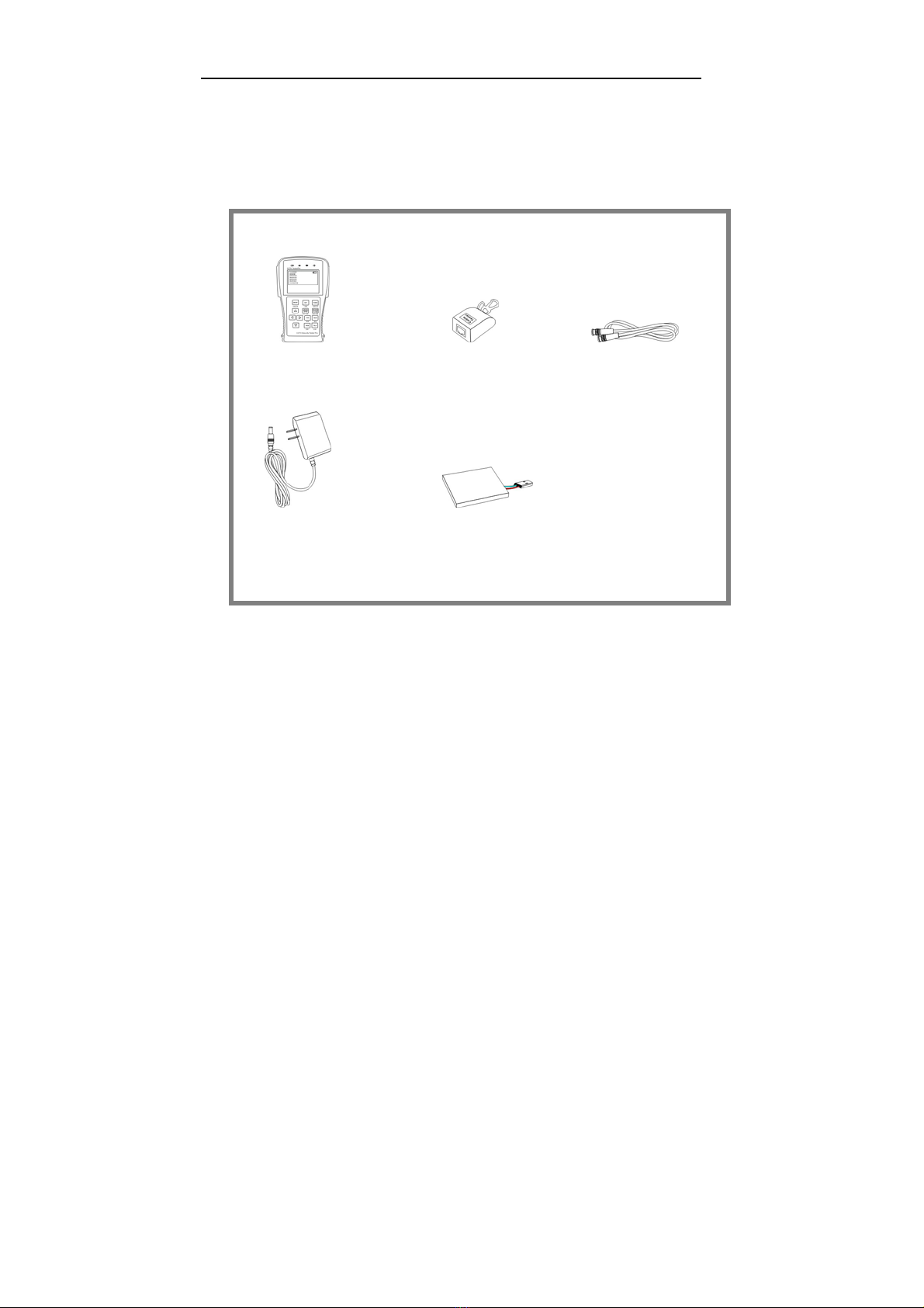
Test-CCTV28 was developed for the On-Site installation and maintenance of video monitoring
system. It can be used for displaying video, controlling PTZ, generating images, capturing data
of RS485 and testing LAN cable etc. Its functions, easy operation, and portability makes it simple
for the CCTV technician to install and maintain CCTV system, improving work efficiency and get
the labor cost down.
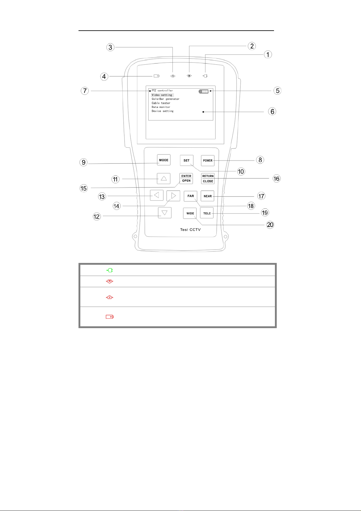
2.1 Features
2.8" TFT-LCD, 960(H)× 240(V)resolution.
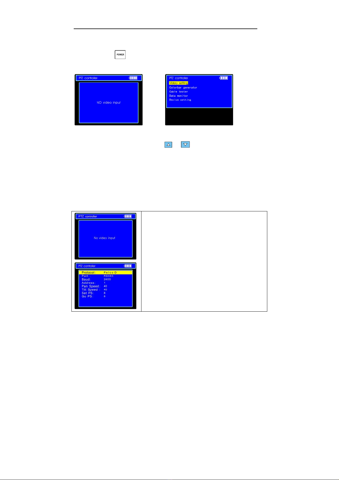
PTZ control. Pan/tilts the P/T unit, zooms in/out the lens, adjusts the focus, aperture and
sets and calls the preset position
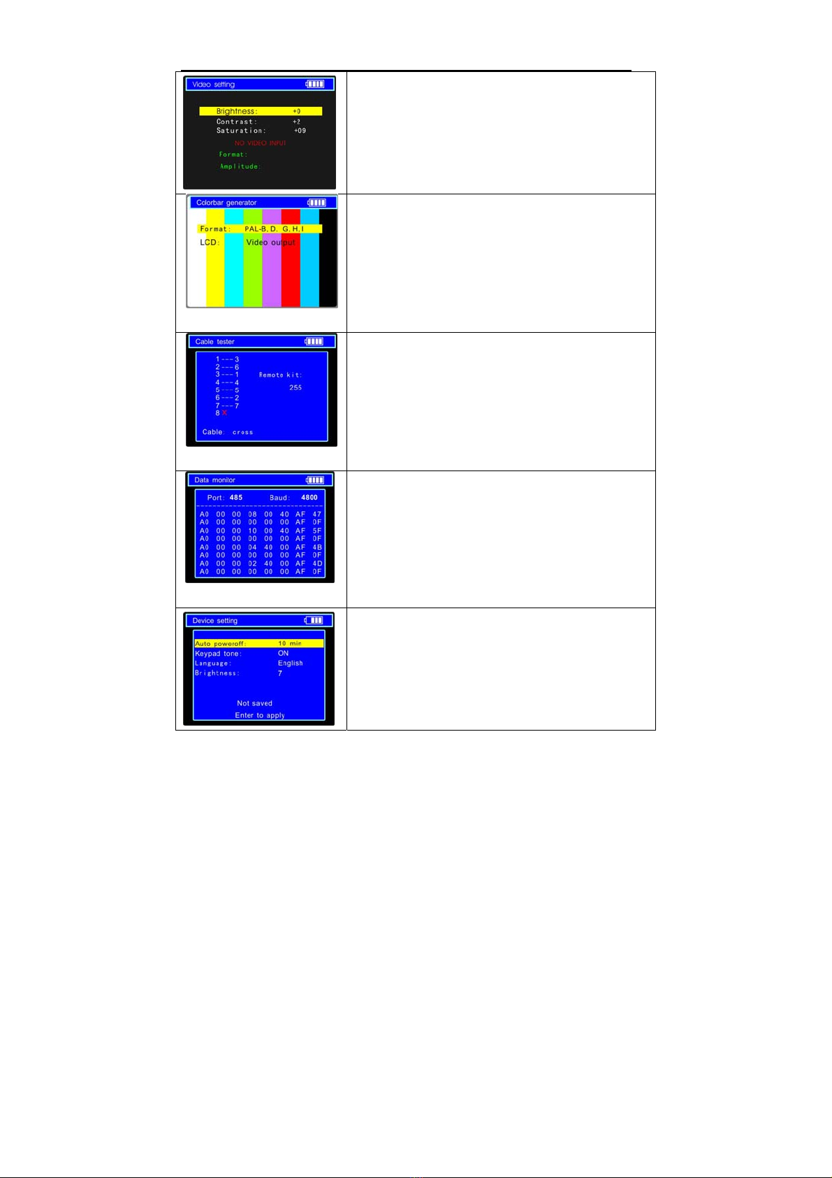
Video displaying. Automatically adapts and displays the video format of NTSC/PAL.
LCD Brightness/Contrast/Color Saturation are adjustable.
Video Level testing, video signals measured in IRE or mV
Video Generating, The PAL/NTSC multi-system Colour Bar generator (seven-system
switchable, transmit/receive seven-system colourful imagines)
Data analysis. Captures and analyzes RS485 controlling data to help the technician to find
out the problem.
Cable testing. It is powerful in testing LAN cable, measuring the connecting status ,
displaying the sequence of connection and the NO. of the LAN cable.
Multi-interface and Multi-baudrate. Support RS232 ,RS485 and RS422 interface; baud rate
ranging from 150, 600 to 19200bps.
Multi-protocol. Supports more than twenty PTZ protocols. For example, PELCO-P,
PELCO-D, SAMSUNG etc.
PTZ address scanning, search up the ID of PTZ camera.
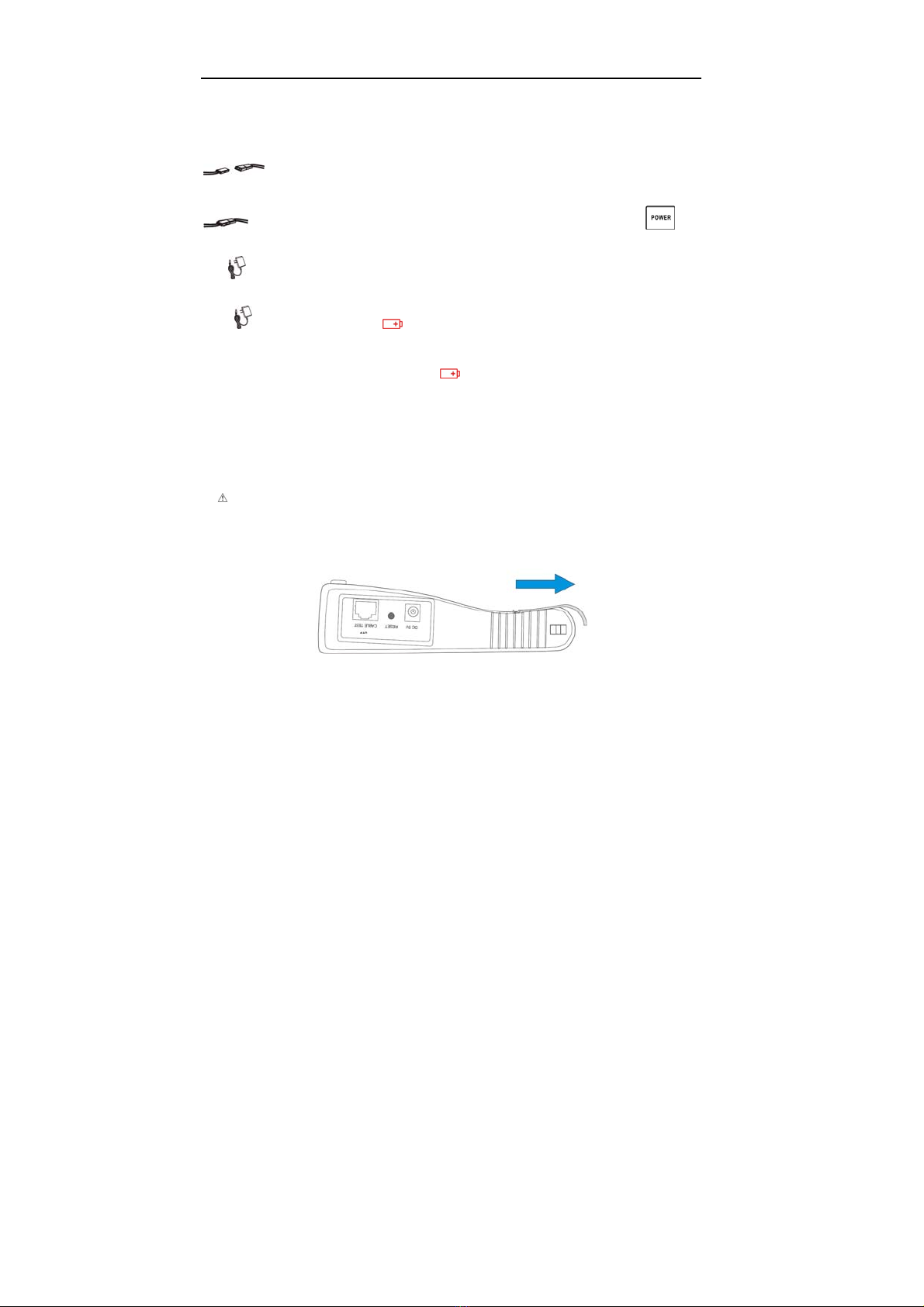
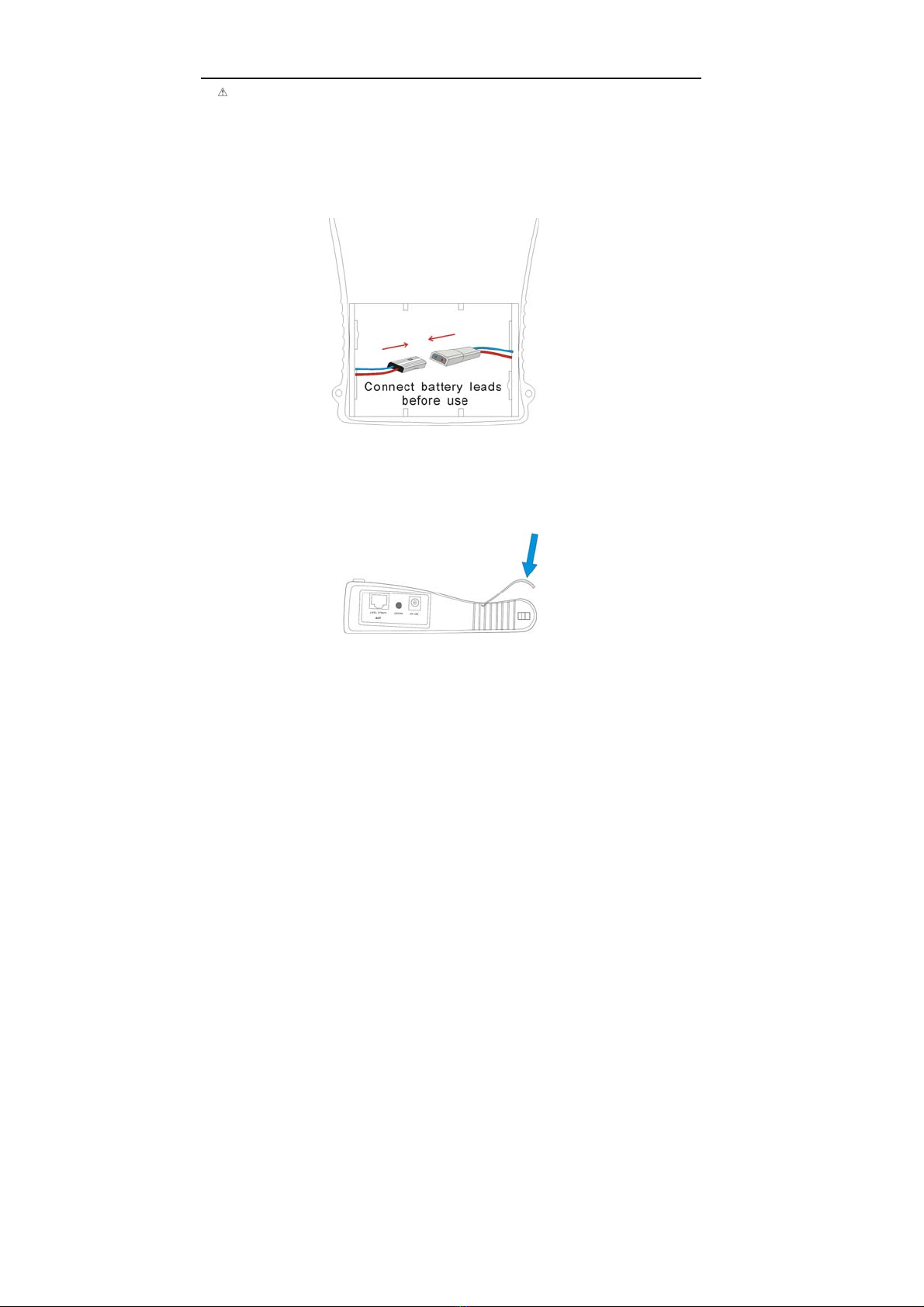
Lithium Ion Polymer Battery (3.7V DC2000mAh). The device employs advanced power
control and protection circuit. The device is high power-efficient, energy saving and
environmental protection. It can last 11 hours for normal use after charging for 4 hours.

Pages from GoVideo Test-CCTV28 User Manual
www.allthings.com.au
Professional design, light and portability, video display and data control are deliberately
integrated, which makes the instrument so simple, practicable, easy for use that the training
is almost unnecessary for an operator to be skillful.
1.Test-CCTV28 3.LANCableTester 5.BNCCable
6.Safetycord
7. RS485 data cable
2. Power Supply (5V 2A) 4. Lithium Ion Polymer Battery

Pages from GoVideo Test-CCTV28 User Manual
www.allthings.com.au
2.3 Front Panel
1 The power indicator: it lights green while the tester is powered on.
2 The data-reception indicator: it lights red while the data is being received.
3 The data-transmission indicator: it lights red while the data is being
transmitted
4 The charge indicator: it lights red while the battery is being charged. As
the charging is complete, the indicator turns off automatically.

Pages from GoVideo Test-CCTV28 User Manual
www.allthings.com.au
5 The display Icon of battery electricity: it displays the electric quantity
6 Main-menu: it shows main functions of Test-CCTV28.
7 Sub-menu: Shows and sets the values of functions
8
Long-pressing it more than 2 seconds to turn on/off the tester;
short-pressing to turn on/off the PTZ controller menu displaying.
9
Menu key: it pops up the main-menu; constant-press it or press the
or key can shift between functions
10
Setup key : press it or press left or right key to enter sub-menu to set the
parameters of functions.
11
Upward : Select the item which will be set or add the value of the
parameter. Tilt the PTZ upward.
12
Leftward : Enter the sub-menu or select the parameter whose value will be
changed. Reduce the value of the parameter. Pan the PTZ left.
13
Rightward : Enter the sub-menu or select the parameter whose value will
be changed. Add the value of the parameter. Pan the PTZ right.
14
Downward : Select the item which will be set or reduce the value of the
parameter. Tilt the PTZ downward.
15 Confirm/Open : Confirm the setting of parameters; open the aperture.
16
Return/Close : Return or cancel while setting parameters of the menu;
close the aperture
17 Near focus: Focus the image nearby.
18 Far focus: Focus the image faraway.
19 TELE: zoom in the image

Pages from GoVideo Test-CCTV28 User Manual
www.allthings.com.au
20 WIDE: zoom out the image
2.4 Side view
Left Side
Top View
Right Side
22 Reset the default settings of parameters.
23 External power supply (DC, 5V): It is highly recommended to use the equipped power
adapter.
24 UTP cable port: Please use together with UTP LAN cable tester.
25 RS232 interface: RS232 communication for the PTZ.
26 Video input (BNC input interface): Inputs the video.
27 Video output (BNC output interface): Outputs the video.
28 RS485/422 Interface: RS485/RS422 communication for the PTZ.
29 Hole for the safety cord.

Pages from GoVideo Test-CCTV28 User Manual
www.allthings.com.au
2.5 Installing the Battery
The tester has built-in lithium ion polymer rechargeable battery. The battery cable inside battery
cabin should be disconnected for safety during transportation!
Prior to the use of the instrument, the battery cables inside the battery cabin should
be well connected and the color of cables should be at the same side.
Usually it need not to disconnect the cable at the normal use, pressing key
continuously can power on or off the tester.
At the first time of use, the batteries should be completely exhausted and then
recharged for 4 or 5 hours.
The Charge Indicator lights red when charging the battery, The charge indicator
turns off automatically when the charging is completed.
△ Notice: When the Charge Indicator turns off, the battery is approximately 90%
charged. The charging time can be extended for about 1 hour and the charging
time within 8 hours will not damage the battery.
△ The tester can work as usual while it is being charged, however. But the charging time
will be extended.
Press the RESET key at the right of the instrument to restore the default settings when
the instrument works abnormally.
Unlock the battery cover by pushing horizontally as the direction illustrated

Pages from GoVideo Test-CCTV28 User Manual
www.allthings.com.au
Warning: Connect the terminal of the battery with the direction illustrated. Please take
care of the polarity of terminal.
(The wires of the same color should be both at the one side)
Lock the batteries by pressing as the direction illustrated

Pages from GoVideo Test-CCTV28 User Manual
www.allthings.com.au
3. Operation
3.1 Power on
Continuously press (at least 2 seconds) to power on/off the Test-CCTV28. When
Test-CCTV28 powers on,press MODE key the main-menu will pop up.
Menu & Functions
Press MODE key continuously or press the or key to select the function (PTZ
controller, Video settings, Color Bar generator, LAN cable tester, Data monitors, Device setting)
and enter corresponding function setting sub-menu. Press SET key to set the parameters in
function sub-menu.
Note: When the Test-CCTV28 is powered on, it will return to the function which is being operated
before it is turned off.
1. PTZ controller
Display the input video images. Pan/tilt the P/T unit and zoom
in/ out the image. Setup the controlling parameters like protocol,
communication port, baud rate, PTZ ID, pan/tilt speed; set and
call preset position.

Pages from GoVideo Test-CCTV28 User Manual
www.allthings.com.au
2. Video setting
Adjust the LCD brightness, Contrast, Color saturation.
Video Format displaying and Video level testing
3. Colour Bar generator
Output or receive seven different forms of video color bar to
tester monitor, cable or other equipment.
4. Cable tester
Test LAN cable or telephone cable.
The connecting condition and the sequence of wires will be
displayed, as well as the serial number of the cable tester kit.
5. Data Monitor
Captures the protocol from the controlling system and display
command data. It is helpful to debug and maintain RS485
communication.
6. Device setting
Set the parameters of the Test-CCTV28 (Auto poweroff/
Keypad tone/Language/Brightness)

Pages from GoVideo Test-CCTV28 User Manual
www.allthings.com.au
3.2 PTZ Controller
Display the input video images. Pan/tilt the P/T unit and zoom in/ out the image. Setup the
controlling parameters like protocol, communication port, baud rate, PTZ ID, pan/tilt speed;
set and call preset position.
The following connections should be confirmed before use
a. The Video In interface of the Test-CCTV28 and the output interface of camera
b. Data A+ of the Test-CCTV28 and A+ of the PTZ camera or controlling device, data B- of
the instrument and B- of the PTZ camera or controlling device
Note: Don’t connect communications interface with a circuit the voltage higher than 6V.
a. Press SET key to enter the sub-menu of PTZ controller.
b. Press the or key to select the parameter
which we want to change the value.
c. Press ENTER key to save the change or press RETURN
key to give up the change
d. Press SET key to exit the sub-menu.
e. Press POWER key to full-screen the image
A. Protocol: Select the protocol according to the protocol of the PTZ camera. Up to 21

Pages from GoVideo Test-CCTV28 User Manual
www.allthings.com.au
popular protocols are available, like elco P, Pelco D, Samsung, Yaan, LiLin, CSR600 etc.
B. Port: Select the communication port for the PTZ camera controlling (RS232/422/485)
C. Baud: Select the baudrate according to baudrate of the PTZ camera.(150, 300, … ,
19200bps)
D. Address: Set the ID according the ID of PTZ camera (0~254).
E. Pan Speed: Set the pan speed of PTZ camera (0~63)
F. TiltSpeed: Set the tilt speed of PTZ camera (0~63)
G. Set PS: Setup preset position (0~128)
a. P/T/Z the camera to desired position
b. Press SET key to enter PTZ controller submenu
c. Move the yellow cursor to “Set PS” and then press or key to select the
preset position number.
d. Press ENTER key to complete preset position setting or preset RETURN key to give up
preset position setting.
Tips: Press or key to accelerate the value changing.
H. Go PS: Call the preset position. (0~128) The PTZ camera will go to the desired preset
position.
a. Move the yellow cursor to “Go PS” and then press or key to select the preset
position number.
b. Press ENTER key to complete preset position calling or preset RETURN key to give up
preset position calling.
Tips: Press or key to accelerate the value changing.
The way of calling the OSD menu and preset of the PTZ camera may vary with control
systems from different manufacturers. Please read the operation manual of control system
manufacturer for details. The way of calling OSD provided for reference is calling preset-64.
a. Move the yellow cursor to “PTZ controller” to enter PTZ controller mode

Pages from GoVideo Test-CCTV28 User Manual
www.allthings.com.au
b. Press SET key to enter PTZ controller sub-menu. Press or keytomove
the yellow cursor to “Go PS”,
c. Press or key to select the preset number 64, and then press ENTER key
to call OSD menu of the PTZ controller.
OSD Menu of Dome (For reference only)
MAIN MENU
1. DISPLAY SETUP
2. CAMERA SETUP
3. CONTROL SETUP
4. CAMERA MASK SET
5. PROGRAM
6. PAL CAMERA
7. CAM DEFAULT SET
8. DOME RESET
9. EXIT
MAIN MENU
1. Display configuration
2. Set camera parameters.
3. Set PTZ controlling
4. Set privacy mask
5. Set auto-running functions
6. PAL/NTSC Switch
7. Restore the default settings
8. Reset the dome
9. Exit the main menu
Operate auto-running functions by calling preset position(effective for some brands of
PTZ camera)
Call preset-33—Open Auto-flip function
Call preset-34—Reset zero point of PTZ camera
Call preset-64—Enter the main menu of the PTZ camera
Call preset-95—Enter the main menu of the PTZ camera or stop the PATTERN recording.
Call preset-96—Run pattern-1
Call preset-97—Run preset tour-1
Call preset-98—Run frame Scan
Call preset-99—Run Auto scan

Pages from GoVideo Test-CCTV28 User Manual
www.allthings.com.au
3.4. Video Setting
User can customize the brightness, contrast and saturation of the LCD according to the using
environment , the CCTV tester auto display the format(PAL/NTSC) of video input, and
analysis the input video signal level.
a. Press the or key to select the parameter which we want to change the value.
b. Press the or key to change the value. Press ENTER key to save the change
or press RETUR key to give up the change
c. The Video Format and Video Level will be displayed in the lower portion of the screen.
If there is no video signal at the Video IN port of the Test-CCTV28, the type of NTSC or
PAL , and Video Level will not be displayed.
Depending on the type of camera connected to the Test-CCTV28, the Video “Format: “ will
automatically change between NTSC and PAL, and the Video Level will automatically
change between IRE (Institute of Radio Engineers) and mV. NTSC signals measured in IRE
units, PAL signals measured in mV.
The Video Level should be within the indicated range. Levels that are too low will result in a
dim picture with reduced dynamic range. A Video Level that is too high will result in
washed out pictures with decreased. The Test-CCTV28 will display “Normal” when video
levels are 1000mV±20%, “Exceed” or “Weak” will be displayed when video level out of
1000mV±20%.
3.5. Colorbar generator
(Output video at any mode)
Output or receive seven different forms of video color bar to test monitor, video cable or
other equipment.

Pages from GoVideo Test-CCTV28 User Manual
www.allthings.com.au
a. Press the or key to select the parameter which we want to change the
value.
b. Press the or key to change the value.
c. Press ENTER key to save the change or press RETURN key to give up the change
3. 6 Cable Tester
Test LAN cable or telephone cable.
Connect LAN cable or telephone cable with the Test-CCTV28 and cable tester. And then the
connecting status, cable type and the sequence of wires will be displayed, as well as the serial
number of the cable tester kit
The right picture shows line1-7 are closed, line8 is open and the number of the cable tester box is
255

Pages from GoVideo Test-CCTV28 User Manual
www.allthings.com.au
Straight-through Line Cross Line Open Line or Short
Line
3.7. Data monitor
Capture the command data from RS485 controlling system.
a. Connect the RS485 or RS232 interface of controlling system with the RS485 or RS232
interface of the Test-CCTV28 (In case of RS485, A to A, B to B)
b. Press SET key and then press or key to select communication port according
to the system connection. Press SET key to save the change.
d. Press or key to select the baud rate according to the baud rate of controlling
system and then press SET key to save the change and capture command data from
controlling system.
e. Press RETURN key to clear the screen.
3.8 Device setting
Set the parameters of the Test-CCTV28
Auto power off: Setting the time of auto shut-down.(Disable,5,10,…,60)
Disable: Disable the “Auto power off” function. 5 means the CCTV will power off
after 5 minutes when there is no any operation.
Keypad tone: Open or close the beep of pressing keypad.
Language: Select language of OSD menu
Brightness: Setting the brightness of OSD menu and background.(0~7)

Pages from GoVideo Test-CCTV28 User Manual
www.allthings.com.au
a. Press or key to move the parameter we want to change.
b. Press or to change the value.
c. Press ENTER to save the change or press RETURN key to give up the change.
3.9 PTZ address scanning
Search up the ID of PTZ camera.
Note: Please isolate the PTZ camera with other PTZ cameras before searching up. Otherwise all
the PTZ cameras in the same system will pan at the same time.
Press keys to “Device setting” menu:
Press key to confirm after change “Address search:”
to “on”, which add address scan sub-menu. Press to switch the sub-menu as illustrated:
(Note: The system returns to “OFF” after shutdown, and the
scan sub-menu closes automatically. Set “ON” again for next
use.)
Press key to set: protocol, communication port,
communication rate, make them same as the PTZ camera
Press or key, the address values is constantly on the rise or decrease.
NEAR: The tester will search up the ID quickly and continuously (from 1 to 256). When
the ID is searched, the PTZ camera will pan right. At this time, please press any
key to stop searching up.
FAR: The tester will search up the ID quickly and continuously (from 256 to 1). When
the ID is searched, the PTZ camera will pan left. At this time, please press any
key to stop searching up.

Pages from GoVideo Test-CCTV28 User Manual
www.allthings.com.au
WIDE: The tester will search up the ID step by step (from 1 to 256). When the ID is
searched, the PTZ camera will stop panning.
FAR: The tester will search up the ID step by step (from 256 to 1). When the ID is
searched, the PTZ camera will stop panning.
Press button, the tester will search up the ID quickly and continuously(from 1 to 256).
When the ID is searched, the PTZ camera will pan right. At this time, please press any key to stop
searching up. Press manual single-step decreasing button, the tester will search up the ID
step by step (from 256 to 1). When the ID is searched, the PTZ camera will stop panning.
Press button , the tester will search up the ID quickly and continuously(from 256 to 1).
When the ID is searched, the PTZ camera will pan left. At this time, please press any key to stop
searching up. Press manual single-step incremental button,the tester will search up the ID
step by step (from 1 to 256). When the ID is searched, the PTZ camera will stop panning.
Press the direction control button to adjust Speed Dome Camera. Press button to quit from
the address-scanning function menu.
Table of contents
Popular Test Equipment manuals by other brands

Extech Instruments
Extech Instruments IRC350 user guide

Tripp Lite
Tripp Lite T015-POE owner's manual

Delta
Delta UNOKIT2 user manual

One-Tool
One-Tool OTB620 product manual

Adeunis RF
Adeunis RF LoRaWAN AS923 PULSE user guide

Kyoritsu Electrical Instruments Works, Ltd.
Kyoritsu Electrical Instruments Works, Ltd. 8031 CE instruction manual