Autel MaxiTPMS TS601 User manual

i
Trademarks
Autel®, MaxiSys®, MaxiDAS®, MaxiScan®, MaxiTPMS®, MaxiRecorder®, and
MaxiCheck®are trademarks of Autel Intelligent Technology Corp., Ltd.,
registered in China, the United States and other countries. All other marks are
trademarks or registered trademarks of their respective holders.
Copyright Information
No part of this manual may be reproduced, stored in a retrieval system or
transmitted, in any form or by any means, electronic, mechanical, photocopying,
recording, or otherwise without the prior written permission of Autel.
Disclaimer of Warranties and Limitation of Liabilities
All information, specifications and illustrations in this manual are based on the
latest information available at the time of printing. Autel reserves the right to
make changes at any time without notice. While information of this manual has
been carefully checked for accuracy, no guarantee is given for the
completeness and correctness of the contents, including but not limited to the
product specifications, functions, and illustrations.
Autel will not be liable for any direct damages or for any special, incidental, or
indirect damages or for any economic consequential damages (including the
loss of profits).
IMPORTANT
Before operating or maintaining this unit, please read this manual carefully,
paying extra attention to the safety warnings and precautions.
For Services and Support:
pro.autel.com
www.autel.com
1-855-288-3587/1-855-AUTELUS (North America)
0086-755-86147779 (China)
For technical assistance in all other markets, please contact your local
distributor.

ii
Safety Precautions and Warnings
To prevent personal injury or damage to vehicles and/or the scan tool, read
this instruction manual first and observe the following safety precautions at
a minimum whenever working on a vehicle:
⚫Always perform diagnosis or service in a safe environment.
⚫Wear safety eye protection that meets ANSI standards.
⚫Keep clothing, hair, hands, tools, test equipment, etc. away from all
moving or hot engine parts.
⚫Operate the vehicle in a well-ventilated work area: Exhaust gases are
poisonous.
⚫Put blocks in front of the drive wheels and never leave the vehicle
unattended while running tests.
⚫Use extreme caution when working around the ignition coil, distributor
cap, ignition wires and spark plugs. These components create
hazardous voltages when the engine is running.
⚫Keep a fire extinguisher suitable for gasoline/chemical/electrical fires
nearby.
⚫Put the transmission in PARK (for automatic transmission) or
NEUTRAL (for manual transmission) and make sure the parking brake
is engaged.
⚫Always turn the ignition off before connecting/disconnecting the OBD II
Cable to/from the TPMS tool; otherwise it may cause the Malfunction
Indicator Light (MIL) to turn on.
⚫Refer to the user’s manual for the vehicle being serviced and adhere to
all diagnostic procedures and precautions. Otherwise personal injury or
unneeded repairs may result.
⚫Keep the TPMS tool dry, clean, free from oil, water and grease. Use a
mild detergent on a clean cloth to clean the outside of the TPMS tool
when necessary.

iii
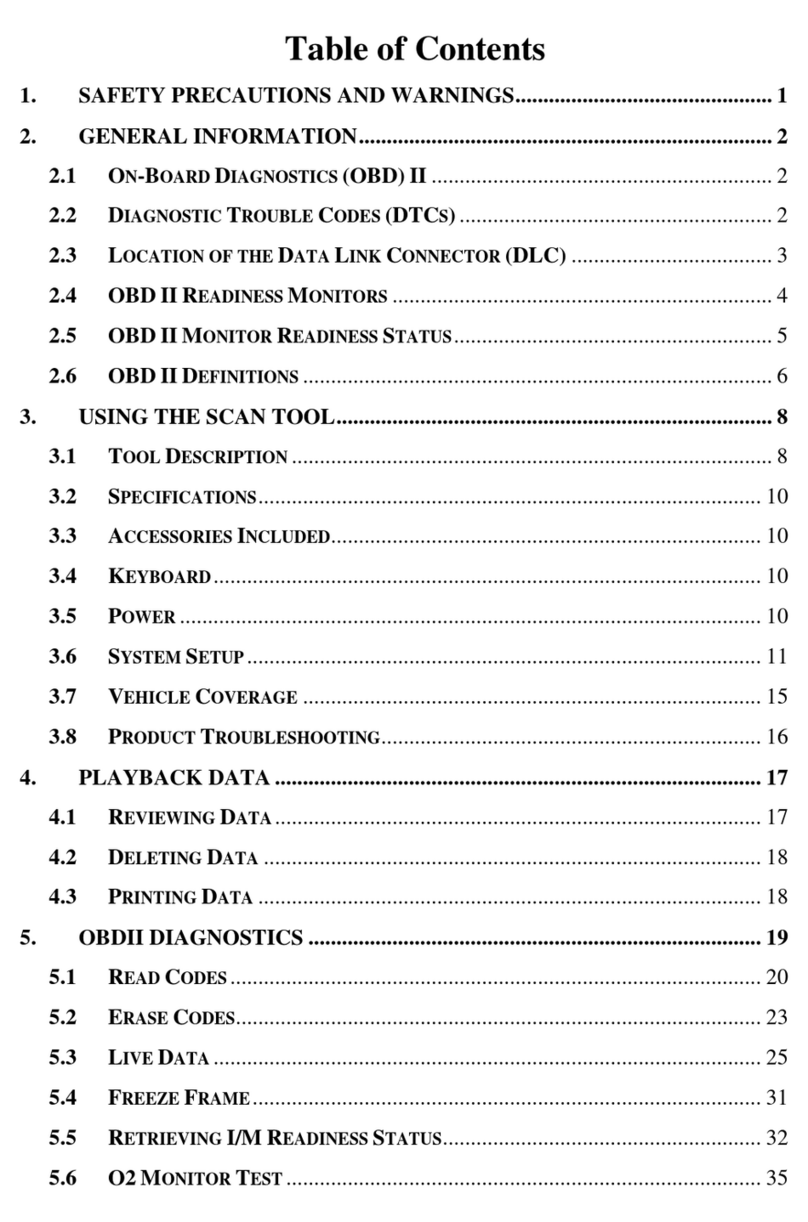
CONTENTS
SAFETY PRECAUTIONS AND WARNINGS............................................................ II
1USING THE MANUAL ................................................................................1
CONVENTIONS...............................................................................................1
2GENERAL INFORMATION.........................................................................3
TPMS SYSTEM REVIEW..................................................................................3
TPMS LEGISLATION ......................................................................................3
TPMS TELL-TALE LIGHT ................................................................................4
BENEFITS OF TPMS......................................................................................4
3TOOL INFORMATION................................................................................5
TOOL DESCRIPTION .......................................................................................5
SPECIFICATIONS............................................................................................6
ACCESSORIES ...............................................................................................7
ICONS...........................................................................................................7
KEYBOARD....................................................................................................8
BATTERY CHARGING ......................................................................................8
POWER UP BY DLC.......................................................................................8
SYSTEM SETTING ..........................................................................................9
PRODUCT TROUBLESHOOTING ......................................................................16
4TPMS CHECK & DIAGNOSTICS .............................................................18
TPMS SENSOR CHECK................................................................................18
TPMS RELEARN .........................................................................................27
AUDIT REPORT............................................................................................39
5TPMS SENSOR PROGRAMMING...........................................................41
AUTO CREATE.............................................................................................41
MANUAL CREATE.........................................................................................50
COPY BY OBD............................................................................................52
COPY BY ACTIVATION...................................................................................53
6OBD II DIAGNOSTICS .............................................................................58
READ CODES ..............................................................................................59
ERASE CODES ............................................................................................61
LIVE DATA ..................................................................................................61

iv
FREEZE FRAME ...........................................................................................63
RETRIEVE I/M READINESS STATUS................................................................64
O2 MONITOR TEST......................................................................................66
ON-BOARD MONITOR TEST ..........................................................................68
COMPONENT TEST.......................................................................................69
VIEW VEHICLE INFORMATION ........................................................................70
MODULES PRESENT.....................................................................................71
7RKE & RF MONITOR ...............................................................................73
8REVIEW DATA.........................................................................................74
9PRINT AND UPDATE...............................................................................76
PRINT DATA................................................................................................76
SOFTWARE UPDATE.....................................................................................77
10 COMPLIANCE INFORMATION................................................................82
11 WARRANTY AND SERVICE....................................................................84
LIMITED ONE YEAR WARRANTY.....................................................................84
SERVICE AND SUPPORT................................................................................85

1
1 Using the Manual
This manual contains device usage instructions.
Some illustrations shown in this manual may contain modules and optional
equipment that are not included on your system. Contact your sales
representative for availability of other modules and optional tools or
accessories.
Conventions
The following conventions are used.
Bold Text
Bold text is used to highlight selectable items such as buttons and menu
options.
Example:
⚫Tap OK.
Terminology
The term “select”means highlighting a button or menu item and tapping it to
confirm the selection.
Notes and Important Messages
The following messages are used.
Notes
A NOTE provides helpful information such as additional explanations, tips,
and comments.
Important
IMPORTANT indicates a situation which, if not avoided, may result in
damage to the test equipment or vehicle.

2
Hyperlinks
Hyperlinks or links that take you to other related articles, procedures, and
illustrations are available in electronic documents. Blue italic text indicates a
selectable hyperlink and blue underlined text indicates a website link or
email address link.
Illustrations
Illustrations used in this manual are samples, the actual testing screen may
vary for each vehicle being tested. Observe the menu titles and on-screen
instructions to make correct option selection.

3
2 General Information
TPMS system review
A tire pressure monitoring system (TPMS) is an electronic system designed
to monitor the air pressure inside the pneumatic tires on various types of
vehicles. TPMS report real-time tire-pressure information to the driver of the
vehicle, either via a gauge, a pictogram display, or a simple low-pressure
warning light. TPMS can be divided into two different types –direct (dTPMS)
and indirect (iTPMS). TPMS are provided both at an OEM (factory) level as
well as an aftermarket solution.
TPMS Legislation
In the United States, the United States Department of Transportation
(NHTSA) released the FMVSS No. 138, which requires an installation of a
Tire Pressure Monitoring System to all new passenger cars, multipurpose
passenger vehicles, trucks, and buses that have a gross vehicle weight
rating (GVWR) of 4,536 kg (10,000 lbs.) or less, except those vehicles with
dual wheels on an axle, as of 2007. In the European Union, starting
November 1, 2012, all new models of passenger cars must be equipped
with a TPMS, with even tighter specifications that will be defined by the
UNECE Vehicle Regulations (Regulation No. 64). From November 1, 2014,
all new passenger cars sold in the European Union must be equipped with
TPMS. On July 13, 2010, the South Korean Ministry of Land, Transport and
Maritime Affairs announced a pending partial-revision to the Korea Motor
Vehicle Safety Standards (KMVSS), specifying that “TPMS shall be
installed to passenger vehicles and vehicles of GVW 3.5 tons or less, ...
[effective] on January 1, 2013 for new models and on June 30, 2014 for
existing models”. Japan is expected to adopt European Union legislation
approximately one year after European Union implementation. Further
countries to make TPMS mandatory include Russia, Indonesia, the
Philippines, Israel, Malaysia and Turkey.

4
TPMS Tell-tale Light
When diagnosing TPMS systems, you should understand what the TPMS
tell-tale light means.
When turning the ignition OFF to ON, the TPMS tell-tale should come on,
and then go off, which indicates the system is working fine. If the light stays
on, there would be a pressure problem. If the light flashes, there would be a
system problem, which can range from faulty sensors to sensors on the
vehicle that haven’t been learned to that vehicle.
Benefits of TPMS
The significant advantages of TPMS are summarized as follows:
⚫Fuel saving.
⚫Extended tire life.
⚫Decreased downtime and maintenance.
⚫Improved safety.
⚫Environmental efficiency.

5
3 Tool Information
Tool Description
Figure 3-1
1) SENSOR SLOT –holds the MX-Sensor needs to be programmed.
2) LCD DISPLAY –displays the menus and test screens.
3) FUNCTION BUTTONS –corresponds with “buttons” on screen for
executing commands.
4) UP SCROLL BUTTON –moves up through menu and submenu
items in menu mode. When more than one set of data are retrieved,
use this button to move up to previous screens for additional data. It is
also used to view previous trouble code when viewing DTCs.
5) N BUTTON –cancels a selection (or action) from a menu or return
to previous menu.

6
6) LEFT SCROLL BUTTON –when scrolling through a screen of data
or text, moves to previous character and views additional information
on previous screens if recorded data content covers more than one
screen.
7) HELP BUTTON –provides help information.
8) POWER BUTTON –long press this button to turn on/off the tool; or,
short press the button to return to Home screen.
9) DOWN SCROLL BUTTON –moves down through menu and
submenu items in menu mode. When more than one set of data are
retrieved, use this button to move down to next screens for additional
data. It is also used to view next trouble code when viewing DTCs.
10) RIGHT SCROLL BUTTON –when scrolling through a screen of
data or text, moves to next character and view additional information
on next screens if recorded data content covers more than one screen.
11) Y BUTTON –confirms a selection (or action) from a menu.
12) FUNCTION BUTTON/TEST BUTTON –corresponds with “buttons”
onscreen for executing commands, or commences a TPMS Test in
sensor activation mode.
13) USB PORT –connects the TPMS tool to PC for software update, data
printing or battery charging.
14) POWER PORT –connects the TPMS tool to the mains with the charger
supplied for battery charging.
15) SD CARD SLOT –holds SD card.
16) OBD II CONNECTOR –connects the TPMS tool to the vehicle’s Data
Link Connector (DLC).
NOTE
Figures and illustrations, product’s characteristics and functions, and
included accessories in this User Manual are provided for reference only
and may differ from actual product. Product design and specifications may
be changed without notice.
Specifications
1) Display: TFT color display (320 x 240 dpi)
2) Power: 3.7 V Li-polymer battery
3) Operating Temperature: 0°C to 50°C (32°F to 122°F)

7
4) Storage Temperature: -20°C to 70°C (-4°F to 158°F)
5) Dimensions:
Length Width Height
202.2 mm (7.96”) 106.7 mm (4.20”) 37.7 mm (1.48”)
6) Weight: 0.4 kg (0.88 lb.)
Accessories
1) OBD II Cable –provides power to tool and communicates between tool
and vehicle.
2) USB Cable –allows easy online update, data printing, and power
charging via PC connection.
3) Carry Case –used to store the tool.
4) Magnet (Purchase Separately) –used to trigger magnetically
activated sensors (early model TPMS sensors).
5) Power Adapter –charges the built-in battery.
6) SD Card –used to store data.
Icons
1) –indicates battery charging.
2) –indicates there is data stored in the tool.
3) –indicates battery volume.
4) –indicates USB communication with the computer is established.
5) –indicates magnet is required to activate TPMS sensor.
6) –indicates deflation is required to activate TPMS sensor.
7) –indicates One Wheel test mode is selected.
8) –indicates ALL Wheels test mode is selected.
9) –indicates the TPMS tool is sending signals to the tire sensor for
activation and test in activation screen or indicates the sensor
information is read by activation.
10) –indicates the tool communication with the vehicle’s OBD II DLC is
established or indicates the sensor information is read by OBD.

8
Keyboard
No solvents such as alcohol are allowed to clean the keypad or display.
Use a mild nonabrasive detergent and a soft cotton cloth. Do not soak the
keypad as the keypad is not waterproof.
Battery Charging
The TPMS tool has a 3.7 V built-in lithium-ion polymer rechargeable battery.
There are two means of battery charging:
✓To charge battery by power adapter
1) Locate the power port of the device.
2) Connect the device and the power source with the adapter.
✓To charge battery by USB cable
1) Locate the USB port of the device.
2) Connect the device and the computer with the USB cable.
For optimum performance, always keep your tool sufficiently charged. It is
recommended that you charge the tool for over 2 hours before the first use.
NOTE
Only use the power adaptor or USB cable that is included in our pack to
charge this tool. The use of un-approved power supplies may damage your
tool and void the tool warranty.
Power Up by DLC
The tool can also be powered via the vehicle Data Link Connector (DLC).
Just follow the steps below to turn on the TPMS tool:
1) Connect the OBD II Cable to the TPMS tool.
2) Find DLC on vehicle.
⚫A plastic DLC cover may be found for some vehicles and you need to
remove it before plugging the OBD II cable.
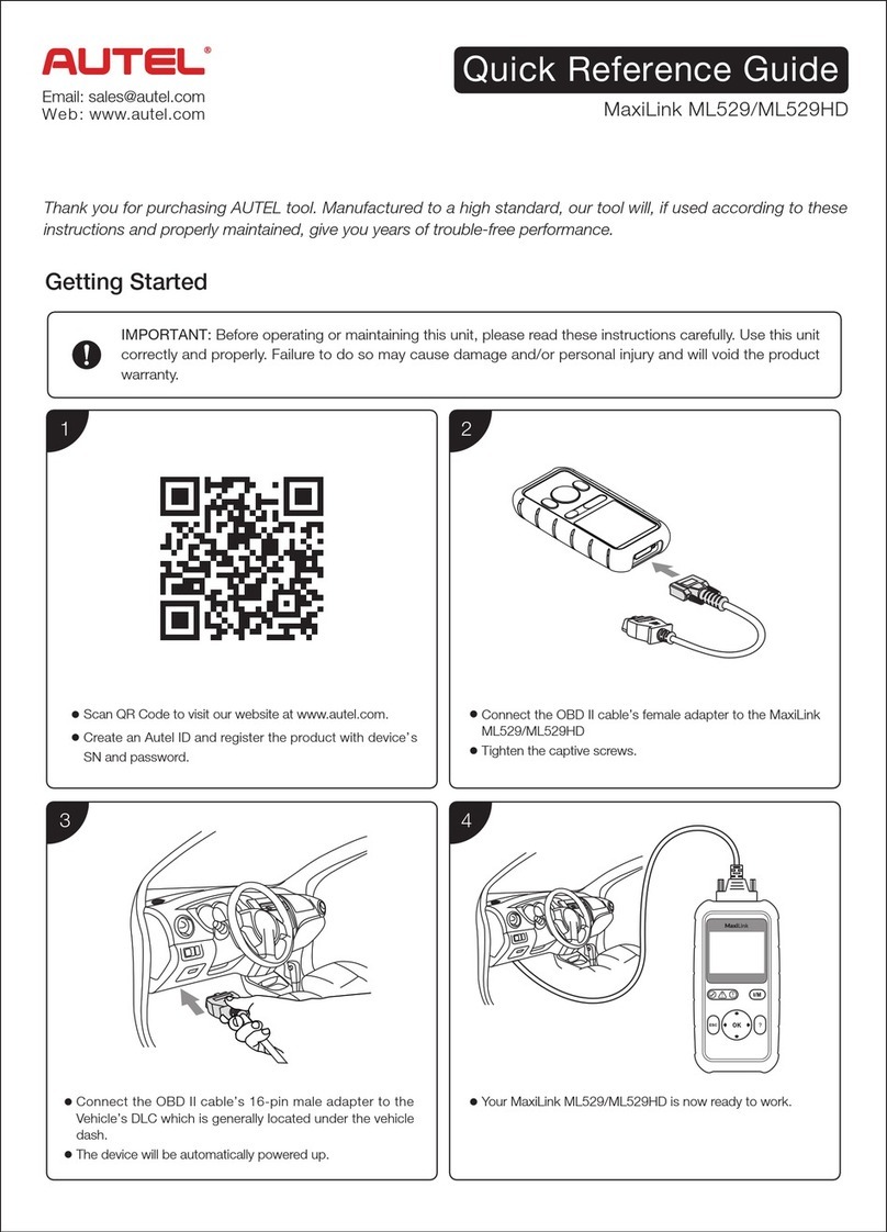
3) Plug OBD II cable to the vehicle’s DLC.
4) Power up the TPMS tool by pressing the Power button, and wait for the
Main Menu to appear.

9
Figure 3-2
System Setting
The tool allows you to make the following adjustments and settings.
1) Market:Selects the area of work, Europe or America.
2) Language:Selects the desired language.
3) Pressure Unit:Sets the pressure unit in kPa, Psi or Bar.
4) Temperature Unit:Sets the temperature unit in degree Celsius or
Fahrenheit.
5) Distance Unit: Sets the distance unit in km or mile.
6) ID Format:Sets the ID displaying in Hexadecimal or Decimal.
7) Beep Set:Turns on/off key-press beep.
8) Wheels:Sets the test modes in One Wheel or All Wheels.
9) Power-off: Sets the time to power off automatically.
10) Date: Allows setting date information of the tool.
11) About:Allows viewing important information of the tool.
⚫Setting will remain until change to the existing settings is made.
To Enter the Setting Menu
From the Main Menu: Use the UP/DOWN and LEFT/RIGHT scroll button to
select Setting, and press the Ybutton. The Setting menu displays as
below.

10
Figure 3-3
Market
This function allows you to switch among the supported corresponding
models for European and American areas.
1) From System Setting screen, use the UP/DOWN scroll button and the
LEFT/RIGHT scroll button to select Market, and press the Y button.
2) From Market screen, use the LEFT/RIGHT scroll button to select the
work area.
3) The tool will load the new database for the selected zone.
Figure 3-4
NOTE
The Market Setting is available for Global version only. The SD card is
required to get the data when changing the market areas. Please select the
correct Market before testing.
Language
⚫English is the default language.

11
1) From System Setting screen, use the UP/DOWN scroll button and
LEFT/RIGHT scroll button to select Language, and press the Ybutton.
2) Use the UP/DOWN scroll button and LEFT/RIGHT scroll button to
select the desired language and press the Ybutton to save your
selection and return to previous menu.
Figure 3-5
Pressure Unit
1) From System Setting screen, use the UP/DOWN scroll button and
LEFT/RIGHT scroll button to select Pressure Unit, and press the Y
button.
2) From Pressure Unit screen, use the LEFT/RIGHT scroll button to
select the desired unit: kPa, Psi or Bar.
Figure 3-6
3) Press the Ybutton to save your settings and return to previous menu,
or press the N button to exit without change.

12
Temperature Unit
1) From System Setting screen, use the UP/DOWN scroll button and
LEFT/RIGHT scroll button to select Temperature Unit, and press the
Ybutton.
2) From Temperature Unit screen, use the LEFT/RIGHT scroll button to
select the desired unit of temperature.
Figure 3-7
3) Press the Ybutton to save your settings and return to previous menu,
or press the Nbutton to exit without change.
Distance Unit
1) From System Setting screen, use the UP/DOWN scroll button and
LEFT/RIGHT scroll button to select Distance Unit, and press the Y
button.
2) From Distance Unit screen, use the LEFT/RIGHT scroll button to
select the desired unit of distance: km or mile.
Figure 3-8

13
3) Press the Ybutton to save your settings and return to previous menu,
or press the Nbutton to exit without change.
ID Format
1) From System Setting screen, use the UP/DOWN scroll button and
LEFT/RIGHT scroll button to select ID Format, and press the Ybutton.
2) From ID Format screen, use the LEFT/RIGHT scroll button to select
the desired ID format.
Figure 3-9
3) Press the Ybutton to save your settings and return to previous menu,
or press the Nbutton to exit without change.
Beep Set
This function allows you to turn on/off the built-in speaker for key pressing.
1) From System Setting screen, use the UP/DOWN scroll button and
LEFT/RIGHT scroll button to select Beep Set, and press the Ybutton.
2) From Beep Set menu, use the LEFT/RIGHT scroll button to select ON
or OFF to turn on/off the beep.

14
Figure 3-10
3) Press the Ybutton to save your selection or the Nbutton to exit without
change.
Wheels
This function allows you to set sensor testing mode in All Wheels or One
Wheel.
1) From System Setting screen, use the UP/DOWN scroll button and
LEFT/RIGHT scroll button to select Wheels, and press the Ybutton.
2) From Wheels screen, use the LEFT/RIGHT scroll button to select All
Wheels or One Wheel mode for TPMS sensor testing.
Figure 3-11
3) Press the Ybutton to save your selection or the Nbutton to exit without
change.
NOTE
In All Wheels mode, the tool will determine if a duplicate sensor ID has
been read. In this case, the tool will display a message “Sensor ID

15
Duplicated.”. In One Wheel mode, the tool will not check the duplication of
sensor ID.
Power-off
1) From System Setting screen, use the UP/DOWN scroll button and
LEFT/RIGHT scroll button to select Power-off, and press the Ybutton.
2) Press the UP/DOWN scroll button to increase or decrease the interval
time for auto power-off, and then press the Ybutton to confirm your
change or the N button to exit without change.
Figure 3-12
NOTE
1. Before the tool powers off automatically, it will save all the TPMS test
data. Next time when the tool is powered on, you may retrieve the
recorded data or return to the last operation.
2. When using external power, the scan tool stays on until you turn it off.
When using internal battery power, the scan tool turns off automatically
after a set time of inactivity.
Date
This function allows setting the date information of the tool.
1) From System Setting screen, use UP/DOWN scroll button and
LEFT/RIGHT scroll button to select Date, and press the Ybutton; wait
for the Date screen to appear.
2) Use UP/DOWN scroll button to increase or decrease the value and
LEFT/RIGHT scroll button to select the item need to change.

16
Figure 3-13
About
This function allows viewing of some important information such as serial
number and software version number of the tool.
1) From System Setting screen, use the UP/DOWN scroll button and
LEFT/RIGHT scroll button to select About, and press the Ybutton; wait
for the About screen to appear.
2) View tool information on screen. Press the N button to exit.
Figure 3-14
NOTE
If the tool is Global version, please select the correct area under Market
Setting before performing test.
Product Troubleshooting
This part describes problems that you may encounter while using the TPMS
tool.
Other manuals for MaxiTPMS TS601
1
Table of contents
Other Autel Test Equipment manuals

Autel
Autel MaxiCheck MX900 User manual

Autel
Autel MaxiPRO MP808S User manual

Autel
Autel AutoLink AL529 User manual

Autel
Autel AutoLink AL419 User manual

Autel
Autel MaxiLink ML529 User manual

Autel
Autel EVO NEST User manual

Autel
Autel MaxiBAS B200 User manual

Autel
Autel AutoLink AL529 User manual

Autel
Autel Autolink AL539B User manual

Autel
Autel MaxiBAS BT609 User manual
Popular Test Equipment manuals by other brands

Huazheng
Huazheng HZJY-15K manual

ChemInstruments
ChemInstruments COF-1000 operating instructions

Testboy
Testboy TB 5300 operating instructions

agratronix
agratronix MT-PRO+ Operator's manual

Desco
Desco 19656 Installation, operation and maintenance instructions

AlkoHAWK
AlkoHAWK AlkoHAWK Beacon owner's manual