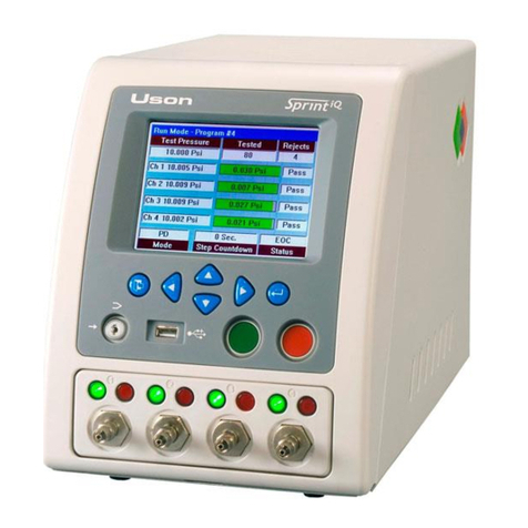
Uson SPRINT LC User manual

SPRINT L
C
Uson
MULTI-AIR TESTER
Owner’s
Guide


Page 3
Guide Version
Release Date: January 2007
To help keep this guide with the correct tester, it is suggested to record the
Sprint LC serial number in this space.
___________________________________ Sprint LC Serial Number
Trademarks
Trademarked names may appear in this manual for purposes of explaining
the capabilities of the Sprint LC tester. Such use is intended to benefit the
trademark owners. There is no intention to infringe on such trademarked
names in any way.
Copyright © 2007 Uson, L.P. All Rights Reserved.
Permission to reproduce this document, in any form, in whole or in part, is
granted to Sprint LC owners with the restriction that all safety
information, cautions, warnings, and the copyright notice remain in place
on such reproductions and that such copies are not for sale or external
distribution..
Information in the Sprint LC Owner’s Guide is subject to change without
notice.
Additional copies of this Sprint LC Owner’s Guide may be purchased
from Uson. Call or mail us your purchase order.
Uson
8640 North Eldridge Parkway
Houston, Texas 77041
(281) 671-2000
www.uson.com

Page 4
Contents
Quick Start 7
Front Panel Controls ................................................9
Back Components ..................................................10
Run Display ...........................................................12
Status Box Messages..............................................14
Decision Lights ......................................................16
Key Commands......................................................17
Test Parameters......................................................18
Troubleshooting ...................................................21
Air Supply..............................................................22
Full Setup 23
Standard vs. Optional Features ..............................24
How This Guide is Organized................................25
Turning On the Power............................................28
Switches and Buttons.............................................30
Setup Menus...........................................................34
Navigation..............................................................36
Parameters Menu ..................................................39
Test Pressure – Setting...........................................40
Coupling.................................................................42
Test Params – Sub-Parameter Menu .....................47
Vacuum Testing.....................................................53
How Sprint LC Works ...........................................54
Connections............................................................60
Run Display ..........................................................62
Units of Measure....................................................68
Serial Port...............................................................70
Input/Output...........................................................86

Page 5
Programming 88
Pressure Decay Testing..........................................90
Occlusion Testing ................................................106
Flow Testing ........................................................112
Burst Testing........................................................124
Creep Testing (subset of Burst) ...........................130
Engineering 134
Calibration: Get Ready ........................................135
Multi-Channel Calibrations .................................136
Calibration Access ...............................................138
Pressure Calibration.............................................140
Flow Calibration ..................................................144
Timer Verification ...............................................152
Engineering Data .................................................153
Physical Laws ......................................................154
Appendices (Optional Features) A-1
A. Electronic Regulator ...................................... A-1
B. Fast Fill........................................................... A-8
C. Additional Manual Regulator......................... A-9
D. I/O Pinout Options ....................................... A-11
E. Serial Commands.......................................... A-15
F. Pass/Fail Jumps............................................. A-17
G. Data Plotting ................................................ A-19
H. Program Names............................................ A-21
I. Crack Testing................................................. A-23
J. Start Options.................................................. A-27
K. Real Time Clock .......................................... A-29
Reference & Index R-1

Page 6
Safety
Follow established safety guidelines about how to install, operate, and
maintain electrical test equipment. In addition, Uson recommends
observing the specific guidelines below when working with the Sprint LC
air tester.
fWear eye protection when working with compressed gas.
fBeware that hazardous voltages and gas pressures could be present
inside the enclosure.
fBefore attempting any maintenance procedure discussed in this
guide, develop an understanding of the procedure and know
exactly how to complete the task
Tester-Specific Information
This guide covers the standard Sprint LC air
tester. Each Sprint LC could be a custom
machine with fewer or added features such
as external components or unique
specifications. Check any additional
information included in the shipment for
application notes about the tester being used.
!
Before using the Sprint LC,
make certain the air supply is
clean and dry and does not
exceed the maximum input
pressure.

Page 7
Quick Start
This section is for Sprint LC owners familiar with the controls and
operation of the tester. If any of the concepts presented here are
unfamiliar, start with the section called Full Setup.
Fast Setup
3Connect clean, dry supply air.
3Connect the power cord and turn on Sprint LC.
3Adjust display contrast for best visibility and set the volume of the
key-press and alarm tone.
3Turn the LOCKOUT keyswitch to program position.
3Set the units of measure to use for pressure, flow volume, and flow
time.
3Enter test parameters for the first program to run.
3Enter test parameters for additional programs if you’re using more
than one program. Don’t forget any required program linking.
3Set communication values for the serial port then connect
peripherals to the I/O port if used.
3Return the LOCKOUT keyswitch to run position. Sprint LC is
now ready to use.
Refresher
For those familiar with the controls and features of Sprint LC.

Page 8
Keypads
ENTER/BACK
PREVIOUS
NEXT
INCREMENT DECREMENT
FIGURE 1
Number Accelerator
The
ENTER/BACK
keypad becomes Accel (Accelerate) when
the
INCREMENT
or
DECREMENT
keypads are held. Tap
ACCEL
to make values change quickly forward or backward.
FIGURE 2
SPRINT LC
12
USER
TIP
Start Switch
LOCKOU
T
Ke
y
switch

Page 9
Front Panel Controls
ENTER/BACK Enter a selection or go back. It also acts to accelerate
the INCREMENT and DECREMENT functions. In run
mode, this keypad accesses the run mode functions
menu.
PREVIOUS Go to the previous menu item. In run mode,
increments the current test when held for three
seconds.
NEXT Go to the next menu item. In run mode, increments
the current test when held for three seconds.
INCREMENT Increase values such as pressure or time, also enters
GoTo Menus. In run mode, acts as a re-test button.
DECREMENT Decrease a setup value such as pressure or time.
START Switch Begins a test cycle. It will abort a test if pressed
during the test cycle. Figure 2.
LOCKOUT Keyswitch Change between run and programming operation.
Figures 2 and 3.
FIGURE 3
Program
key in vertical position
Run
key in horizontal position
LOCKOUT SWITCH

Page 10
Back Component Layout
FIGURE 4
8c
1
3
5
6
78
9
10
8a
8c
4
2

Page 11
Back Components
Overview
1. Foot Switch Socket. Plug the foot switch into this socket if you’re
using the optional foot switch.
2. Contrast Adjustment. Adjust this control to get the best visibility on
the liquid crystal display.
3. Serial Output. This is a connection for interfacing Sprint LC to
computers or printers.
4. Tone Adjustment. Use this control to set tone volume, which affects
both key-press and alarm tone.
5. Input/Output. A connector used to hook up relay input and outputs.
Used for programmable logic controllers and automated test fixtures.
6. Timer Output. A BNC connector providing an output for the internal
timer. It is used to verify timer accuracy for calibration purposes.
7. Pressure Regulator. Controls the air pressure applied to the product
under test. Use this control to set the test pressure.
8. Power Entry Module. The Entry Module has three parts
a. On/Off Switch. “1” is on; “0” is off.
b. Fuse Holder. Holds two 2-Amp, fast-blow fuses.
c. Power Cord Socket. Plug the power cord into this receptacle.
9. Flow Control. Use this precision needle valve to set ramp rate for
burst and creep testing. Typically not used in a flow or pressure
decay test.
10. Gas Supply Connection. Connect house air or other gas to this 1/8-
inch female NPT input port. Input air must be clean and dry.

Page 12
PD 1.2 TEST
Mode Test Time Status
PROGRAM 1
Test Press. Tested Reject
9.993 psig 0 0
psig
Run Display Layout
FIGURE 5
Each message that can appear in
the status box is explained on
pages 14 and 15.
Display Contrast
Remember to set the contrast
on the back of Sprint LC to
get the best visibility on the
liquid crystal display.
!

Page 13
Run Display – Overview
Sprint LC shows the run display during all test cycles in every test mode.
If multiple programs are linked, Sprint LC shows the run display for the
program currently running. More information about each item on the run
display is in the Reference/Index section.
1. Program Header. Ninety-nine programs may be stored in memory.
The header shows which program is currently running.
2. Test Pressure Box. Shows preset pressure before a test is started
and actual pressure applied during a test. In a Flow and Pressure
Decay test it holds the final fill or stabilize pressure during the test
time.
3. Tested Box. Shows number of tests. Counts total times pass and
fail lights turn on. Counts up to a maximum of 65,535.
4. Reject Box. Shows number of rejects. Counts the number of times
the fail light turns on. Counts up to a maximum of 65,535.
5. Main Digital Readout. Shows pressure drop, flow, or burst value
depending on what kind of test is being run.
6. Units of Measure. Measurement units change depending on the
type of program (flow or pressure) being run. The desired units of
measure are selected in the Units Setup Menus.
7. Bar Graph. An analog trend of what the current program is
measuring. Helps operators see whether values are going up or
down, and how rapidly values change.
8. Mode Box. Sprint LC can operate in many modes – i.e. pressure
decay (PD), flow, burst, etc. This box shows in what mode or test
type Sprint LC is operating.
9. Test Time Box. The time of each phase counts down during a test.
The phases vary depending on the type of test being run.
10. Status Box. Shows what phase a decay test is in and possible
reasons for an unsuccessful test. Pages 15 and 16 provide
descriptions of all status box messages.

Page 14
Status Box Messages
The status box on the run display shows information before, during, and
after a test. Three kinds of facts are displayed in the status box—test type
set to run, test phase, and results of the completed test.
Test Mode Status
These messages appear before a test is started. Press and hold down the
START switch to see the kind of test Sprint is set to run. If Sprint is set to
run linked tests, the status box shows the first test type in a series. After
releasing the START switch, the test begins.
Pd Sprint is set to run a pressure decay test.
OCC Sprint is set to run an occlusion test.
Flow Sprint is set to run a flow test.
Burst Sprint is set to run a burst test.
Test Phase Status
These messages display during a test and before pass or fail lights turn on.
Couple One or more coupling valves have opened, or a test
is in a wait period to allow an external fixture to
activate.
Fill Product is being filled with air.
Stab A pressure decay leak test is in stabilization phase.
Test A pressure decay, flow, or burst test is in test
(measured) phase.
Dump The dump valve has opened to atmosphere to release
pressure in the product and test circuit.

Page 15
Test Result Messages
Test result messages in the status box can help when
adjusting test parameters. Repeated P ERR, for instance,
could indicate the need to widen the pressure error
tolerance by increasing the Press. Error value.
Test Results Status
These messages appear at the end of test to tell operators whether a test
passed or why a test was unsuccessful.
PASS The product stayed within all test parameters of each
test that was run.
ABORT The start button was pressed, ending the test.
PERR Test pressure was above or below the pressure error
tolerance set in the parameters menu.
GROSS In a pressure decay test, the test pressure fell below
the minimum during stabilization phase.
LEAK In a pressure decay test, the pressure decay exceeded
the reject level setpoint.
OCC In an occlusion test, the pressure decay did not reach
the reject level setpoint
LOW In a flow or burst test, flow or burst was below the
minimum setpoint.
HIGH In a flow or burst test, flow or burst was above the
maximum setpoint.
OVER In a flow test, the pressure was above the maximum
pressure the flow sensor can withstand.
NO In a burst test, Sprint did not detect a large enough
pressure change to detect a burst.
USER
TIP

Page 16
Decision Lights
The only machine output operators need to watch during most tests are the
pass and fail lights. A pass light means the test cycle was completed and
all test values were within tolerances stored in each program that ran.
A fail means at least one test
parameter went out of
tolerance some time during a
test cycle. The fail light turns
on if a gross leak occurred, a
pressure error value is
exceeded, or the product
exceeded an established
pressure or flow tolerance.
Repeated failures can indicate
Sprint LC or external fixtures
have set-up problems.
If a fail light turns on during a
test, the operator can read the
status box on the run display
to see why the test was
unsuccessful. The
status box might indicate GROSS, LEAK, HIGH, or any of seven other
messages.
Alert Tone
The alert tone (set with the volume control on the back of the Sprint LC)
turns on for five seconds whenever the fail light turns on. If the tone
volume is turned completely down, the operator won’t hear an alert.
The same volume control used to set the alert tone also sets the key-press
sound level.
PASS/FAIL LIGHTS
Pass
Green
Light
Fail
Red
Light
Figure 6

Page 17
Key Commands
Re-Test
If Sprint LC says there’s a product failure, operators can re-test the
product by pressing the INCREMENT keypad. Re-test works only if the last
test failed. Operators can’t re-test a part that has passed. If the operator re-
tests a failed product, the tested counter does not advance. Sprint LC
counts only once for each test to keep an accurate log of the total number
of products tested.
Run Mode Functions
From the run mode, access the Run Mode Functions menu. Enter the run
mode function menu by pressing the ENTER/BACK keypad. This menu
allows the operator to change the current program, print a program header,
print a test summary or clear the counters.
See page 29
Abort
Press the START switch during the test, and ABORT pops up in the run
display status box show the process has stopped. Aborted tests don’t
register on the tested or reject counters.
Linked Programs
To get a pass light, the product being tested needs to stay inside all
established tolerances. If multiple programs are linked, the product must
stay inside tolerances for every program in the linked series.
Stop at First Failure
The fail light turns on at the first out-of-tolerance
condition and stops all tests. For example, Sprint LC does
not run program-3 if the product fails in program-2.
USER
TIP

Page 18
Test Parameters
Test parameters are setpoints and tolerances that tell Sprint LC how to
conduct a test and decide whether a product is accepted or rejected. Test
parameters are entered in the parameters menu.
When Test Parameters are Available
If there are existing test values, it is simply a matter of entering those
values into the Sprint LC. Once all values are set correctly, the Sprint LC
is either ready to use or ready for fine tuning.
For those users previously familiar with Sprint LC testers, a new Sprint
LC may have more features from one used previously. Some test
parameters may need adjustment to take advantage of these newer
features.
Proceeding Without Test Parameters
If there are no existing test values, it will be necessary to do some
experimenting to arrive at values for pressures, flow rates, and times best
suited to your product. Very little effort to program Sprint LC is required
after test parameters are established. Yet, coming up with test values can
take a little work when starting from scratch.
The Over-Testing Trap
Optimum setup values are typically established after trial and error when
working with known good and bad product samples. An important point is
not to over-test product by setting overly tight leak tolerances thinking that
absolutely no leak is acceptable. Experimentation may prove that a small
pressure drop occurs simply due to how the product behaves during
pressurization. Many products create conditions that merely appear to be
small leaks when pressurized.

Page 19
Setting Test Time
The size and material of parts to be tested are important factors when
determining test time. Parts that are both small and rigid typically require
short test times. Parts that are both large and flexible generally require
longer test times.
Choose the Desired Engineering Units
Set units of measure before going to the parameters
menu. Sprint LC allows programming in units most
familiar to the user, and then switch to different
units of measure for operation. Sprint LC handles all
conversions automatically.
USER
TIP
ESTABLISH TEST TIMES
Shortest Tim
e
Lon
g
est Tim
e
Small and Rigid
Small and Flexible
Large and Rigid
Large and Flexible

Page 20
Fine Tuning
After entering the basic parameters into a program, it is possible to fine-
tune the setup. A few tips:
If external fixtures are not being used, set coupling time to zero.
If product blows out of external fixtures, make sure a sufficiently
long coupling time is chosen.
If gross failures occur when testing a flexible product, try
increasing fill time.
Add fill and stabilize time to slow the decay rate and make it more
consistent.
If the test doesn’t need a dump valve to vent product pressure after
testing, set the dump parameter to off.
In a flow test, set test time long enough for the product under test
to fill with pressure and produce a stable flow rate.
If repeated P ERR messages show up in the status box, try
widening the pressure error tolerance or adding more fill time.
Put Sprint LC to Work
When everything is programmed and checked out, Sprint LC is ready to
work and start testing products. A few tips:
Explain controls and run display messages to operators.
Keep external connections to the product under test as straight,
rigid, and direct as possible. Flexible connections can cause
inconsistent readings.
Put Sprint LC in a place where the pressure regulator and other
controls on the back won’t get moved around or damaged.
Table of contents
Other Uson Test Equipment manuals