GP:50 216/316 User manual

Pressure, Level & Temperature Transmitters &
Transducers
INSTALLATION MANUAL
Models 216/316
TABLE OF CONTENTS
1
.
Introduction
1.1 Product Description
1.2 Warning
1.3 Unpacking/Inspection
1.4 Using this manual
2
.
Installation
2.1 Mounting/process connection
2.2 Power Supply
2.3 Wiring/Grounding
2.4 Environment
3
.
Operation
&
Maintenance
4.
Troubleshooting
&
Return Information
5
.
Warranty
6
.
Appendi
ces

Pressure, Level & Temperature Transmitters &
Transducers
2770 Long Rd, Grand Island, NY 14702 USA
Phone: (716) 773-9300 Fax: (716) 773-5019 Email: [email protected] www.gp50.com
1. INTRODUCTION
1.1 Product Description
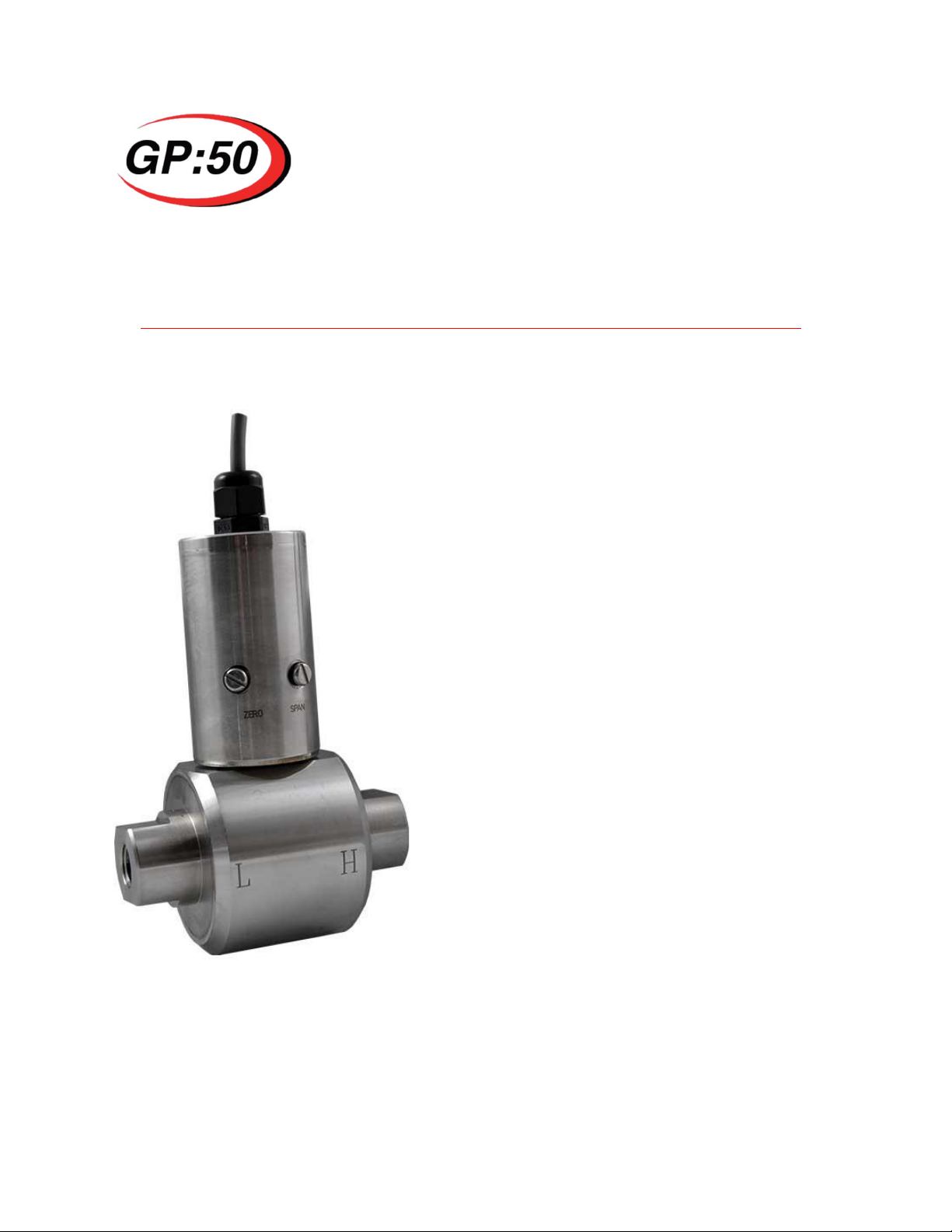
Model 216/316 is a Low Range High line Differential Pressure Transducer with ranges as
low as 2.5”WCD to 200 PSID and digitally corrected accuracy up to +- 0.05% FSO.
These are often used for measuring fluid flow across a primary device such as an orifice
plate but can also be used for other differential pressure applications.
1.2 Warning
Pressurized vessels and associated equipment are potentially dangerous. The product
described in the guide should be operated only by personnel trained in the procedures
that will assure safety to themselves, to others, to the equipment, and to the product.
Specific warnings are noted as in specific installation/operation sections.
1.3 Unpacking and Inspection
All models covered in this manual are carefully tested, inspected and packed. Upon
receipt of the shipment thoroughly inspect the transducer. If you see any visible signs of
obvious shipping damage, notify the freight company immediately.
1.4 Using this manual
This manual is intended to help the end user install, maintain, and provide general
service of GP:50 Model 216/316 Low Range High Line Differential Pressure Transducer.
The user should have a general understanding of current loops & general instrument
control. All aforementioned models are precision instruments and should be given the
same care as any other precision instrument during installation and operation.
2. INSTALLATION
2.1 Mounting/Process Connection
Model 216/316 is a position sensitive device and its orientation may cause zero shift if
mounted differently from the orientation the unit was calibrated in (standard orientation
has the pressure ports in the horizontal position). Although this is the case, once
determined, this shift can be adjusted for using the zero adjustment screw on the unit. It
is also noted the lower the pressure range the greater the “orientation shift”. The standard
process connections is ¼ “NPT F but can be ordered with optional pressure ports.
Consult factory for availability. Installation of the device shall be in accordance with
industry standard pipe fitting requirements for this size. During installation or removal
torque should only be applied at the wrench flats provided on the pressure port. As a
general rule of thumb, the device shall be “wrench-tight”to avoid leakage from the
process connection.
Ensure media is compatible with 316 stainless steel (standard material, optional materials
available) check part number to verify wetted material to avoid premature corrosion of the
diaphragm. This can cause performance degradation and eventual sensor failure.

Pressure, Level & Temperature Transmitters &
Transducers
2770 Long Rd, Grand Island, NY 14702 USA
Phone: (716) 773-9300 Fax: (716) 773-5019 Email: [email protected] www.gp50.com
Properly tighten process connections before applying pressure to insure no leaks or
mechanical failure can occur.
Never insert sharp objects into diaphragm. This could cause permanent damage the
sensor and / or mechanical failure/diaphragm rupture.
2.2 Power Supply Connection
Consult power requirements listed on the Calibration Recorded provided with each
serialized individual unit. For best operation the pressure transducer needs clean
regulated power with output impedance less than 20 ohms. As loads are added to the
current loop (galvanic barriers, current measuring devices resistors), the minimum
excitation voltage must increase in order to maintain proper operating voltage. Refer to
datasheet for additional electrical specifications.
2.3 Wiring & Grounding
Consult wiring listed under Electrical Connections on the Calibration Record provided
with each serialized individual unit. A 4-20mA transmitterrequires a DC power supply
(typically 10-36 VDC) and mA meter wired in a current loop. Connect the red wire of the
transducer to the + terminal of the power supply and the black wire of the transducer to
the + input terminal of the meter. Connect the –input terminal of the meter to the –
terminal of the power supply.
A VDC transducer (3 wire) requires a DC power supply (10-36 VDC) and voltmeter.
Connect the Red wire from the transducer to + on the power supply, the green wire to the
+signal of the VDC meter and the Black wire from the transducer to both the –Power on
the power supply and –signal on the VDC meter
Do not run wires next to power lines, electrical systems, motors, generators, or any other
equipment which may generate a significant amount of electrical noise or magnetic fields.

Pressure, Level & Temperature Transmitters &
Transducers
2770 Long Rd, Grand Island, NY 14702 USA
Phone: (716) 773-9300 Fax: (716) 773-5019 Email: [email protected] www.gp50.com
2.4 Environment
The operating temperature range should be from 32°F (0°C) to 180°F (82°C). Mount the
unit as close to the process as possible with the ambient temperature surrounding the
electronics falling within the operating range.
Protect electrical connection from direct/continued exposure to fluids. Moisture ingress
can occur and cause eventual electrical failure.
3. OPERATION & MAINTENANCE
Model 216/316 is designed to produce the respective output ( 0-5 Vdc, 4-20 mA) in direct
proportion to pressure. Specific pressure range, input voltage requirements and electrical
connections are marked on unit. Appropriate mating connections are required for proper
installation and safety. Other port and electrical connections are available and noted as
option code in part number.
.
Install only after verifying both input power and line pressure are off and at zero.
Replace broken fasteners (available through the factory) as they may compromise the
seal and cause contamination and/or electronics failure.
Observe safe ESD handling precautions to avoid static damage to sensitive components.
4. TROUBLESHOOTING & RETURN INFORMATION
No output
- Verify power supply voltage meets transducer requirements
- Check wiring connections
- Verify pressure if being applied
- Verify output load is not shorted
Erratic output or zero drift
- Verify pressure applied is constant

Pressure, Level & Temperature Transmitters &
Transducers
2770 Long Rd, Grand Island, NY 14702 USA
Phone: (716) 773-9300 Fax: (716) 773-5019 Email: [email protected] www.gp50.com
- Verify power supply remains within specifications
- Inspect electrical connections for discontinuity or damage
- Verify output with a multi-meter
- Check insulation resistance between amplifier and transducer case
Slow Response
- Verify pressure port is not clogged
* If the problem persists, please call the factory as indicated below for assistance. Please
have the following information ready:
·Serial number
·Model number
·Loop setup details (power supply, resistor, cable routing/length)
·Which action caused device failure
Contact: sales@gp50.com
Repairs should only be done by GP:50. Repairs done by customer will void any
warranties and may cause permanent damage to unit. Repairs done by customer on
Intrinsically Safe units will void the approvals and are a potential explosion hazard.
Returned products that have been exposed to hazardous substances should be cleaned
prior to return and should include the Material Safety Data Sheet for all substances.
5. WARRANTY
GP:50 warrants its products to the original customer/purchaser against defects in material and
workmanship for a period of one (1) year from the date of delivery by GP:50, as shown in its
shipping documents, subject to the following terms and conditions:
Without charge GP:50 will repair or replace products found to be defective in materials or
workmanship within the warranty period provided that:
1. The product has not been subjected to abuse, neglect, accident, incorrect wiring (not
provided by GP:50), improper installation or servicing, or use in violation of instructions
furnished by GP:50.
2. As to any prior defect in materials or workmanship covered by this warranty, the product has
not been repaired or altered by anyone except GP:50 or its authorized service agencies.
3. The serial number has not been removed, defaced or otherwise changed.

Pressure, Level & Temperature Transmitters &
Transducers
2770 Long Rd, Grand Island, NY 14702 USA
Phone: (716) 773-9300 Fax: (716) 773-5019 Email: [email protected] www.gp50.com
4. Examination discloses, in the judgment of GP:50, a defect in materials or workmanship which
developed under normal installation, use and service.
5. GP:50 is notified in advance of, and approves, the return by issuing a Return Material
Authorization Number; and the products are returned to GP:50 transportation prepaid.
Products returned without an RMA number will not be accepted and be returned to sender at
sender’s expense.
THIS WARRANTY IS THE ONLY WARRANTY AND IS IN LIEU OF ANY OTHER WARRANTY EXPRESSED OR IMPLIED,
INCLUDING ANY WARRANTY OR MERCHANTABILITY OR FITNESS. NO REPRESENTATIVE OR PERSONS ARE
AUTHORIZED TO GIVE ANY OTHER WARRANTY OR TO ASSUME FOR GP:50 ANY OTHER LIABILITY IN CONNECTION
WITH THE SALE OF ITS PRODUCTS. GP:50 DOES NOT ASSUME THE COSTS OF REMOVAL AND/OR INSTALLATION OF
THE PRODUCT OR ANY OTHER WORKMANSHIP, OR WILL GP:50 BE LIABLE FOR ANY CONSEQUENTIAL DAMAGES
RESULTING FROM THE USE OR INSALLATION OF ITS PRODUCT.
Contact our website http://www. GP50.com for a copy of our repair policy or call our repair dept.
Copyright© 2008 GP:50
All rights reserved. This specification must not be reproduced in any form without written permission of
the copyright owner.
Table of contents
Popular Transducer manuals by other brands

novotechnik
novotechnik TM1 Series user manual

Simrad
Simrad 50-200 COMBI C - REV D installation manual

MAMAC SYSTEMS
MAMAC SYSTEMS EP-313 installation instructions

Balluff
Balluff BTL7-A50 Series user guide

Sutron
Sutron ACCUBAR 5600-0120-2 Operation & maintenance manual

Spectrum Technologies
Spectrum Technologies 3669 product manual

Knick
Knick VariTrans P 42000 TRMS user manual

S+S Regeltechnik
S+S Regeltechnik AERASGARD RFTF -CO2 Operating Instructions, Mounting & Installation

novotechnik
novotechnik RFC-4800 CAN user manual

M-system
M-system 18RP instruction manual

Balluff
Balluff BTL7-S5-M Series user guide

promesstec
promesstec UMU 100-A-B user manual