bergmann BCT20 User manual

General
201803 en - 2 -
1 General
1.1 Identification
☐BCT20
Type:
Vehicle identification number
(VIN):
Delivery date:
1.2 Manufacturer
Ludwig Bergmann GmbH
+49 (0)4444 - 2008-0
+49 (0)4444 - 2008-88
-
Hauptstraße 64-66
49424 Goldenstedt
info@l-bergmann.de
www.Bergmann-Goldenstedt.de
1.3 Spare Parts Stock
Spare Parts Stock
+49 (0)4444 - 2008-16
+49 (0)4444 - 2008-25
-
Hauptstraße 64-66
49424 Goldenstedt
ersatzteil@l-bergmann.de
www.Bergmann-Goldenstedt.de
1.4 Customer Service Management
Jörg Kammacher
+49 (0)4444 - 2008-15
+49 (0)4444 - 2008-43
-
Hauptstraße 64-66
49424 Goldenstedt
kundendienst@l-bergmann.de
www.Bergmann-Goldenstedt.de

General
- 3 - 201803 en
1.5 Preface
Dear customer,
You have made a good choice! We would like to thank you for placing your trust in us by purchasing a
BERGMANN Product.
The Ludwig Bergmann GmbH, 49424 Goldenstedt (Lower Saxony) - a medium sized family business in its third
generation - has been successfully active in the manufacturing of agricultural machinery and transport
equipment for over one hundred years. It is one of the major manufacturers and providers of adapted
technology for professional farming operations and farm contractors.
The combination of experience and a contemporary, innovative technology is one of our greatest strengths.
Constant alignment with the needs and desires of customers, adapting to changing technical requirements, the
continual development and improvement of our products and not to forget the "feel" for the customer, have
made BERGMANN a reliable worldwide farming partner.
With our wide range of products, consisting of manure spreaders, universal spreaders, forage transport trailers,
silage trailers, transfer trailers, and special bodies, we offer economical solutions that prove themselves in the
field day after day.
Please check the product for possible shipping damage upon receipt. Check the product against the delivery
note to ensure that no parts or special equipment are missing. In order to reimburse you for damages, we need
your complaint immediately.
Read these operating instructions and all other supplied operating instructions carefully before using the product
for the first time. Follow the instructions for proper operation, care and maintenance in order to ensure that your
product is always ready for use and has a long service life. It is important that the safety notices listed in these
operating instructions are observed. All product operators must have read these operating instructions prior to
operation and must be familiar with the product functions.
We wish you every success with your BERGMANN product.
Ludwig Bergmann GmbH –Maschinenfabrik
Goldenstedt
1.6 Copyright
© Copyright by Ludwig Bergmann GmbH, 2018
All rights reserved
Reprinting (including extracts) is only permitted with the permission from Ludwig Bergmann GmbH.

General
201803 en - 4 -
1.7 Table of Contents
1General.................................................................................................................... 2
1.1 Identification ...................................................................................................................... 2
1.2 Manufacturer...................................................................................................................... 2
1.3 Spare Parts Stock.............................................................................................................. 2
1.4 Customer Service Management........................................................................................ 2
1.5 Preface................................................................................................................................ 3
1.6 Copyright............................................................................................................................ 3
1.7 Table of Contents .............................................................................................................. 4
1.8 Table of Figures................................................................................................................. 5
1.9 Using These Operating Instructions................................................................................. 6
1.9.1 Indexes and References....................................................................................................................6
1.9.2 Depiction of Action Instructions and Listings.....................................................................................6
1.9.3 Depiction of Action-Related Warning Symbols..................................................................................7
1.9.3.1 Design of warning symbols ...........................................................................................................7
1.9.3.2 Signal words and colouring...........................................................................................................7
1.9.4 Depiction of Important Notices ..........................................................................................................7
1.9.5 Definition of Terms ............................................................................................................................8
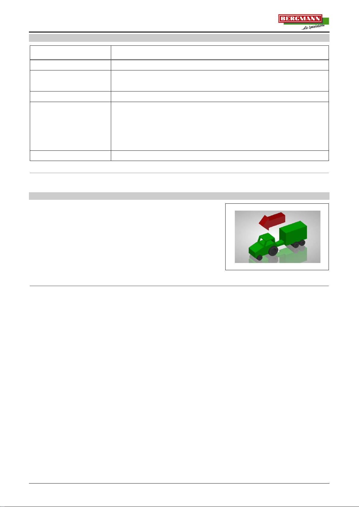
1.9.6 Directional References ......................................................................................................................8
2Safety ...................................................................................................................... 9
2.1 Intended Use...................................................................................................................... 9
2.2 Basic Safety Instructions................................................................................................ 10
2.2.1 Electric System................................................................................................................................10
3Operation.............................................................................................................. 11
3.1 Terminal BCT20 ............................................................................................................... 12
3.1.1 Emergency Control..........................................................................................................................12
3.1.2 Installing the BCT20 Terminal.........................................................................................................13
3.1.3 Connecting the Terminal .................................................................................................................14
3.1.3.1 BCT20 Terminal Connection Diagram........................................................................................14
3.1.3.1.1 Connection line CAN-BUS.................................................................................................15
3.1.3.1.2 BCT20 terminal connection line.........................................................................................15
3.1.4 BCT20 Terminal User Surface ........................................................................................................16
3.1.5 Switching the BCT20 Terminal On and Off.....................................................................................18
3.1.6 Select Function................................................................................................................................18
3.1.7 Change Settings..............................................................................................................................18
3.1.8 BCT20 Terminal Display..................................................................................................................19
3.1.9 BCT20 Terminal Menu Structure.....................................................................................................19
3.1.9.1 Menu 1/4: Driving on roads.........................................................................................................20
3.1.9.2 Menu 2/4: Unloading...................................................................................................................20
3.1.9.3 Menu 3/4: Trip counter................................................................................................................22
3.1.9.4 Menu 4/4: Loading ......................................................................................................................23
3.1.10 Quick Start with BCT20 Terminal....................................................................................................25
3.1.11 Adjusting Scraper Floor...................................................................................................................26
3.1.12 Lock / Unlock Steering Axle.............................................................................................................29
3.1.13 Function Memory A + B...................................................................................................................30
3.1.13.1 Setting Mode:..........................................................................................................................31
4Index of Technical Terms.................................................................................... 34

General
- 5 - 201803 en
1.8 Table of Figures
Image 1: Directional references ..............................................................................................................................8
Fig. 2: Terminal BCT20.........................................................................................................................................12
Fig. 3: Installation ..................................................................................................................................................13
Fig. 4: BCT20 terminal connection diagram..........................................................................................................14
Fig. 5: BCT20 user surface ...................................................................................................................................16
Fig. 6: Display........................................................................................................................................................19

General
201803 en - 6 -
1.9 Using These Operating Instructions
1.9.1 Indexes and References
Table of contents / Headings
The table of contents and the headings in these operating instructions provide for quick orientation in the
chapters.
Table of Figures:
The table of figures in these operating instructions makes it possible to scroll directly to the desired images
using the respective name
Index of Technical Terms:
In the index of technical terms it is possible to find specific topics in the operating instructions using keywords
which are listed in alphabetical order. The index of technical terms can be found at the end of these operating
instructions.
Cross References:
For further information on a topic in these operating instructions or another document, a cross-reference to the
relevant section can be found at the end of the section. Chapters, subchapters and sections are enclosed in
quotation marks.
Example:
BERGMANN contact information can be found in the chapter "Contact Info & Contact Persons".
The page number of the respective chapter, subchapter or section can be found in the table of contents or in the
index of technical terms.
1.9.2 Depiction of Action Instructions and Listings
Action Step:
A dot (•) in front of the sentence defines an action step which must be carried out.
Example:
Carry out action.
Action Sequences:
Multiple dots (•) in front of the sentence define an action sequence which must be carried out.
Example:
Carry out action 1.
Carry out action 2.
Carry out action 2.
Listings:
Multiple dashes (-) before each sentence define listings.
Example:
- Listings 1
- Listings 2
- Listings 3.

General
- 7 - 201803 en
1.9.3 Depiction of Action-Related Warning Symbols
1.9.3.1 Design of warning symbols
SIGNAL WORDS!
Type and source of danger
Possible result(s) of the danger
Measures to avoid the danger
1.9.3.2 Signal words and colouring
DANGER!
The signal word "Danger" identifies a hazard with a high degree of risk. Failure to avoid
the hazard will result in death or serious injury.
WARNING!
This signal word identifies a hazard with a moderate degree of risk. Failure to avoid the
hazard can result in death or serious injury.
CAUTION!
This signal word identifies a hazard with a low degree of risk. Failure to avoid the hazard
can result in minor or moderate injury.
1.9.4 Depiction of Important Notices
NOTICE
Indicates a requirement for particular behaviour or an action, as well as tips for use and
particularly useful information for proper use of the machine.
This information will help you to make optimum use of all machine functions. Failure to observe
these notices can lead to machine malfunctions or damage to the environment.

General
201803 en - 8 -
1.9.5 Definition of Terms
Term
Explanation
Machine
SILAGE TRAILERS is referred to using the term machine in this document.
Danger
Danger is a condition or situation in which the possibility of a health risk exists.
The danger arises from a possible injury or disease-causing spatial and/or
temporal coincidence from a source of danger.
Manufacturer
Ludwig Bergmann GmbH
Adjustment elements
Adjustment elements are parts of the controller that detect operator input
signals, usually made by hand or foot. There are many different adjustment
elements, such as buttons, levers, switches, knobs, slide controllers, joysticks,
handwheels, pedals, keyboards, and tactile screens. Adjustment elements may
be located on the machine itself or, as with remote controls, at a certain
distance from the machine and connected to the machine for example by cable
or by radio, optical or acoustic signals.
Third persons
Third persons are all other persons other than the operator themselves.
1.9.6 Directional References
Directional references such as
- front
- rear
- left
- right
- etc.
Are always indicated in the direction of travel. (see Image 1).
right
Front
rear
left
Image 1: Directional references

Safety
- 9 - 201803 en
2 Safety
This chapter contains important information for the owner and the operator to ensure safe and trouble-free
operation of the machine.
NOTICE
Observe all safety instructions in these operating instructions and in the supplementary
documents!
Most accidents happen when the simplest safety regulations are not observed. By observing all
safety instructions in these operating instructions, you will help to prevent accidents.
2.1 Intended Use
The terminal
- is intended exclusively for use on approved compatible machines and equipment for agricultural applications.
Intended use also includes:
- observing all notices and instructions in these operating instructions,
- compliance with the operating, maintenance and repair conditions prescribed by the manufacturer,
- the exclusive use of original spare parts.
All other uses are not permitted and are therefore considered improper.
The owner bears sole responsibility for damages resulting from improper use
- and
- the manufacturer assumes no liability whatsoever.

Safety
201803 en - 10 -
2.2 Basic Safety Instructions
Basic safety instructions always apply to the safe operation of the machine and are summarized in the following
sections.
NOTICE
Failure to observe the safety instructions may endanger persons, the environment or property.
In addition to the basic safety instructions, also observe the special safety instructions listed
in the other chapters of these operating instructions as well as the machine specific safety
instructions.
2.2.1 Electric System
Always disconnect the negative battery terminal before working on the machine's electrical system.
All work on the machine’s electrical system must be carried out by trained electricians.
Touching damaged live parts can cause serious electric shock, injury or death. Damaged insulation and
electrical system components must be repaired immediately by qualified personnel.
Check electrical equipment regularly: Retighten loose connections and replace damaged lines or cables
immediately.
Only use prescribed fuses. The system could be destroyed if stronger fuses are used! Fire hazard!
Be sure to follow the correct sequence when connecting and disconnecting the battery!
oConnecting: first connect the positive terminal, then the negative terminal.
oDisconnecting: first disconnect the negative terminal, then the positive terminal.
The positive terminal must always be covered with the provided protective cover.
Avoid sparks and open flames near the battery. There is a risk of explosion!
The machine is equipped with electronic components and assemblies whose function may be affected by
electromagnetic emissions from other devices. Such affects can be hazardous to personnel if the following
precautions are not followed.
oIf electrical and electronic equipment and / or components are subsequently installed in the
vehicle with a connection to the electrical system, the user must independently verify whether
the installation causes disturbances to the vehicle electronics or other components.
oIt is important to ensure that subsequently installed electrical and electronic components meet
the requirements of the EMV - Directive 89/336/EWG in accordance with the current version
and that they bear the CE symbol.
oFor wiring and installation as well as the max. allowable power use the machine manufacturer's
installation instructions must be followed.
Never equip the machine with unauthorised work lights. The manufacturer assumes no responsibility or
liability for consequential damage to the electrical system.
Learn to operate the terminals properly.
Press the terminal keys with your fingertip. Avoid using your fingernails.
Keep the terminals and accessories in good condition.
Only clean the terminals with a soft cloth moistened with clear water or a bit of glass cleaner.

Operation
- 11 - 201803 en
3 Operation
The "Operation" chapter contains information on the possible machine controls. It describes the individual
functions, the handling and the procedure for operating the machine using a terminal.
The components and machine functions listed in the operating instructions may differ from the machine
standard equipment and are available as optional equipment in some cases. Since these operating instructions
are general, various equipment options can be listed that are not available for your trailer. This also applies to
the images. Images, drawings and 3D illustrations in these operating instructions do not always represent the
exact machine type. However, the information which refers to the illustrations always corresponds to the
machine type in this document.
WARNING!
Failure to observe the safety instructions may result in serious injury or death.
In order to prevent accidents, the operator of the machine must read and observe the safety
instructions in the "Safety" chapter.
WARNING!
Reaching into the machine can cause crushing, shearing, cutting, severing, being caught,
entangled, pulled in and struck in the machine.
These hazards may arise when
- the unsecured tractor and the trailer unintentionally roll,
- power driven tools are not switched off,
- hydraulic functions are activated unintentionally,
- tools or machine components are in operation,
- the tractor engine is switched on inadvertently,
- raised machine components are lowered inadvertently.
All machine operations are dangerous due to possible unintentional contact with driven,
unsecured parts and raised, unsecured machine components.
Therefore the machine must be secured against unintentional rolling and starting before any
work is done on the machine, e.g. Making adjustments or correcting malfunctions.
For this, the notices and instructions in the operating instructions in section
"Commissioning" under "Securing vehicle against unintentional rolling and
starting" are to be observed.

Operation
201803 en - 12 -
3.1 Terminal BCT20
The hydraulic functions are operated using the BCT20 terminal. The
terminal is characterized by
- ON/OFF for terminal,
- rotary / push button,
- ergonomically arranged keys,
- back-lit membrane keypad,
- backlit display,
- freely programmable sequence control of individual functions,
- trip counter,
- a variety of functions.
Fig. 2: Terminal BCT20
Additional hydraulic functions without control block connection have no terminal functionality. Such functions
can be operated directly by the tractor control units according to the hydraulic system manual control after
coupling the supply lines to the tractor.
For this, observe the notices and instructions in the operating instructions in chapter "Functions
and Settings" in the “Hydraulics” section.
NOTICE
Protect the terminal from water.
Store the terminal in a dry room if it is not used for a long period (e.g. in winter).
Disconnect the power supply during installation and repair work. Remove all electronic
components (terminal, BSG, ISO-Gate, etc.) during welding work. Overvoltage can damage
the terminal's electronics.
3.1.1 Emergency Control
WARNING!
Danger due to moving components during emergency control!
Ensure third persons leave the vehicle danger area before using the emergency control on
the control block.
NOTICE
In case of a power failure, check the fuses in the tractor and control unit (supply line). Check
cables and connections.
Electrically controlled hydraulic valves which are used for "Emergency control" can be controlled manually.
For this, observe the notices and instructions in the operating instructions in chapter "Functions
and Settings" in the “Hydraulics” section.

Operation
- 13 - 201803 en
3.1.2 Installing the BCT20 Terminal
NOTICE
The terminal must be mounted in the driver's field of vision and reach so that it is easy to read
and operate. It must not obstruct the view of the tractor's controls or to the surrounding area.
To install the terminal (Fig. 3 / Pos.1) proceed as follows:
Select a suitable position in the tractor cab where you would like to
mount the terminal (Fig. 3 / Pos.1).
Loosen the eyebolts (Fig. 3 / Pos.4) on the bracket (Fig. 3 / Pos.3)
on the back of the terminal (Fig. 3 / Pos.1).
Guide the rod (Fig. 3 / Pos.2) through the holes in the bracket (Fig. 3
/ Pos.3) (the rod is not included, ø22mm).
If the terminal (Fig. 3 / Pos.1) collides with the rod (Fig. 3 / Pos.2)
when moved, the position of the bracket (Fig. 3 / Pos.3) must be
adapted to the terminal (Fig. 3 / Pos.1). For this, loosen the nuts
(Fig. 3 / Pos.5), adjust the terminal (Fig. 3 / Pos.1) and retighten the
nuts (Fig. 3 / Pos.5).
Position the terminal (Fig. 3 / Pos.1) in the desired height. Ensure
that the rod (Fig. 3 / Pos.2) protrudes at least 2cm above the bracket
(Fig. 3 / Pos.3).
Fasten the terminal (Fig. 3/ Pos.1) by tightening the eyebolts (Fig. 3 /
Pos.4) on the rod (Fig. 3 / Pos.2).
Fig. 3: Installation
NOTICE
Ensure that all screws are tightened firmly and that the terminal position cannot change.
1
3
4
2
5

Operation
201803 en - 14 -
3.1.3 Connecting the Terminal
WARNING!
Danger due to incorrect system and supply line connection
Incorrect connection of the supply lines can lead to considerable hazards for persons due to
machine malfunctions.
Before commissioning, check for proper supply line connection.
When connecting the supply lines, ensure that both plugs and sockets are clean and dry. Dirt
and moisture can lead to a short circuits!
Supply lines between tractor and trailer must be laid in such a way that they cannot be
rubbed, clamped, crushed, bent or rub against foreign parts during trailer movement (e.g.
cornering).
3.1.3.1 BCT20 Terminal Connection Diagram
Fig. 4: BCT20 terminal connection diagram
18-14-0709-BTA
Pos.
Name
Design
1
Terminal
BCT20
2
Controller
BSG100 / BSG200
3
Connection line
CAN-BUS
4
Terminal power cable
BCT20
1
2
3
4

Operation
- 15 - 201803 en
3.1.3.1.1 Connection line CAN-BUS
Connect the terminal (Fig. 4 / Pos.1) to the SG100 / BSG200 controller (Fig. 4 / Pos.2) using the CAN-BUS
connection line (Fig. 4 / Pos.3) while taking the following data into consideration:
Connection line CAN-BUS
B10-0237
Plug / CAN, M12, 8 pin
Connect with:
BSG controller
Connections:
CAN
Socket / CAN, M12, 8 pin
Connect with:
Terminal BCT20
Connections:
-
3.1.3.1.2 BCT20 terminal connection line
Connect the power supply cable (Fig. 4 / Pos.4) to the corresponding connections on the wiring harness and
the power supply on the tractor, while taking the following data into consideration:
BCT20 Terminal Power Supply Cable
18-14-0621
Socket / 2 pin (DIN 9680)
Connect with:
Wiring harness
Connections:
Q01
Socket / 2 pin (DIN 9680)
Connect with:
Tractor
Voltage:
12 V DC
Fuse:
25 Amp

Operation
201803 en - 16 -
3.1.4 BCT20 Terminal User Surface
Fig. 5: BCT20 user surface
B10-0233-BTA_20170329
1
Main switch
Switching the terminal On / Off
2
Display
Menu display with the respective functions
3
Light sensor
Controls the back lighting.
4
Signal horn
Signals e.g. “FULL“ or “Scraper floor stop“
(In combination with the light)
5
Indicator light
Signals e.g. “FULL“ or “Scraper floor stop“
(In combination with the signal horn)
6
Rotary / push button
For changing and confirming settings such as the
transport floor speed.
7
Next menu
For changing the menu.
8
Previous menu
For changing the menu.
9
Shift key
For calling up further functions within a menu.
2
10
11
13
14
6
15
12
5
4
3
9
1
7
8

Operation
- 17 - 201803 en
10
Function memory "A"
Programmable sequence of different functions
- Press and hold the key: Functions are called up.
- Release the key: Stop function sequence.
- Pressing and holding the key again within 2
seconds: Function continues.
- Pressing and holding the key again after 2 seconds:
Restarts functions from the beginning.
Setting Mode:
- Press briefly: Setting mode opens.
- Press briefly: The setting mode is closed and
settings are saved.
11
Function memory "B"
12
Auto key
To activate automatic functions, e.g. permanent
activation of the transport floor or automatic filling
system (depending on machine type and menu level)
13
Function keys forward / up
Operating the functions shown in the display
14
Function key back / down
Operating the functions shown in the display
15
Steering axle Lock / Unlock:
Operating the steering axle function
Unlock:
Press key once briefly
(Unlocked: red LED lights up)
Lock:
Press key once briefly
(Blinking LED: Controller closes
steering axle
Locked: red LED off,)
Other machine functions (e.g. work light, tailgate, jack stand, etc.) can be called up by pressing the shift key
(Fig. 5 / Pos.9) and can be operated using the function keys (Fig. 5 / Pos.13+14).

Operation
201803 en - 18 -
3.1.5 Switching the BCT20 Terminal On and Off
Main switch
The terminal is switched on and off by pressing the main switch.
Pressing the switch once switches the device on and pressing it a
second time switches it off again. When the terminal is switched on,
the initial "Road travel" menu is displayed.
3.1.6 Select Function
Function key
forward / up
By pressing the "Function keys forward/up" and "Function keys
back/down", the function displayed above the key is activated, but the
function is only carried out as long as the key is pressed. As long as
the key is pressed, the key LED lights up.
The scraper floor and the pick-up (silage trailer) are special functions.
These are explained in the following sections
Function key
back/down
3.1.7 Change Settings
Rotary/push button
The rotary/push button is used to change the settings.
When in the respective adjustment mask, the frame is
shifted to the setting to be adjusted by turning the
button. Pressing the button once causes the frame to
start blinking. While the frame is blinking, turn the button
to reach the desired setting. After the setting has been
made, the frame stops blinking either when the
rotary/push button is pressed or automatically after two
seconds. The value setting is automatically saved and
the frame can be moved to the next field to be set.

Operation
- 19 - 201803 en
3.1.8 BCT20 Terminal Display
The display is divided into the following areas:
Menu
Function block
Fig. 6: Display
To navigate between the menus and switch between the function blocks within the menu, proceed as follows:
Use the "Menu forward / up" keys to scroll forward to the corresponding menu.
Use the "Menu back / down" keys to scroll forward to the corresponding menu.
Use the "Shift" key to change the function blocks within the selected menu.
NOTICE
If the menu is changed while the functions are active, the active functions will be deactivated.
The operator is notified of this by a warning signal with an indicator light. Only then will the menu
change.
When the function block is changed within the menu, active functions remain active.
3.1.9 BCT20 Terminal Menu Structure
The individual menus are structured as follows:
1/4
Driving on Roads
2/4
Unloading
3/4
Trip counter
4/4
Loading

Operation
201803 en - 20 -
3.1.9.1 Menu 1/4: Driving on roads
Menu 1/4 / Function block 1:
-
-
-
-
-
-
-
-
-
Work light III /
All-round lighting
On
Off
3.1.9.2 Menu 2/4: Unloading
Menu 2/4 / Function block 1:
Pick-up
Raise
Float position:
Press key once briefly
Drawbar
Raise
Lower
Scraper Floor
Switch scraper floor on permanently
The LED lights when the scraper floor is switched on.
Adjust scraper floor speed
The set speed is displayed above the transport floor
pictogram.
Back
Forward (reverse)
Tailgate
Raise
0%:
Tailgate is completely closed.
1 - 10%
Tailgate is raised and in locked /
unlocked position.
11 - 99%
Tailgate is partially open.
100 %:
Tailgate is completely closed.
Lower
Table of contents
Other bergmann Construction Equipment manuals