GP3D Type-L User manual

ASSEMBLY MANUAL
©GP3D 2020
ASSEMBLY MANUAL
Grand Prix Car “Type-L”

INTRODUCTION
Section 1 - Page 2
STEP 1 – THANK YOU!
We would like to thank you for purchasing the GP3D Grand Prix “Type L” RC car kit.
This kit is a totally new fusion of radio control cars, plastic model making, 3D printing and of course
the glorious and iconic “Grand Prix” era of the 1960’s.
The various printed components have been made from carefully selected polymers to achieve
various characteristics, such as; strength, flexibility, impact resistance, colour and texture. This
results in scale looks and colours (without the need for painting unless desired!) whilst ensuring a
durable and functional RC car.
The inherent nature of 3D printing parts means for a given material and shape it will not be quite as
strong as an injection moulded equivalent. To counteract this, we have used the latest available high
quality and hence higher cost 3D printing filaments to ensure an equivalent durability to other plastic
moulded RC kits. More information about these materials is covered in the next step!
We hope you love and enjoy building and driving this model, so we are always available to help and
support and questions or issues you may have. We would also love to receive pictures of your
finished model in your chosen livery that we can add to our online gallery!
Please contact us if needed: grand.prix.3d@gmail.com
Information and all spare parts are available in our online shop: www.GrandPrix3D.com

INTRODUCTION
Section 1 - Page 3
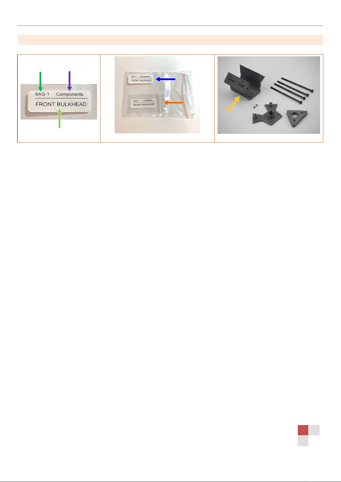
STEP 2 – TERMINOLOGY
3D Printing All the plastic components in this kit are 3D printed using the latest equipment
and high quality, high-cost materials.
Nylon G/X Nylon is a very impact resistant plastic. We use two variants of this material;
NylonG is glass fibre impregnated and is used for the main chassis, bulkheads,
engine bay and suspension components. NylonX is carbon fibre impregnated
and provides a stiffer component mainly used in the front steering links, shock
absorbers and diff output hubs.
PC Blend Is a blended variant of polycarbonate and is extremely strong and impact
resistant. It’s used in the wheels, uprights, gears, axles, battery retainer and
cosmetic parts like the rollover hoops, trumpets and mirrors.
TPU Is an amazing flexible polymer we have used for the body shell and the ‘active’
driver figure! This material is super tough and capable of absorbing any
impacts. The kit comes with all white colour, however we also offer these option
parts printed in colours including; red, blue, yellow and black. The texture and
finish perfectly captures the essence of the grand prix cars of the 1960’s era.
You can also paint them with any flexible paint, such as polycarbonate paint to
achieve your favourite driver/livery!
CPE Is a high-end industrial manufacturing material with resistance to heat and
impacts and available in semi-transparent tinted colours; used for the
windscreens. The windscreens are very thin and exposed, ensuring the scale
appearance, however the tough CPE can still absorb impacts before breaking.
PETG Carbon Is a strong and hard polymer we have used for its cool matt texture for the
dashboard and rocker covers.
PLA Is the most basic and cheapest 3D printing material, we’ve only used it for the
cosmetic engine bay and gearbox detail panels due to its fine accuracy.
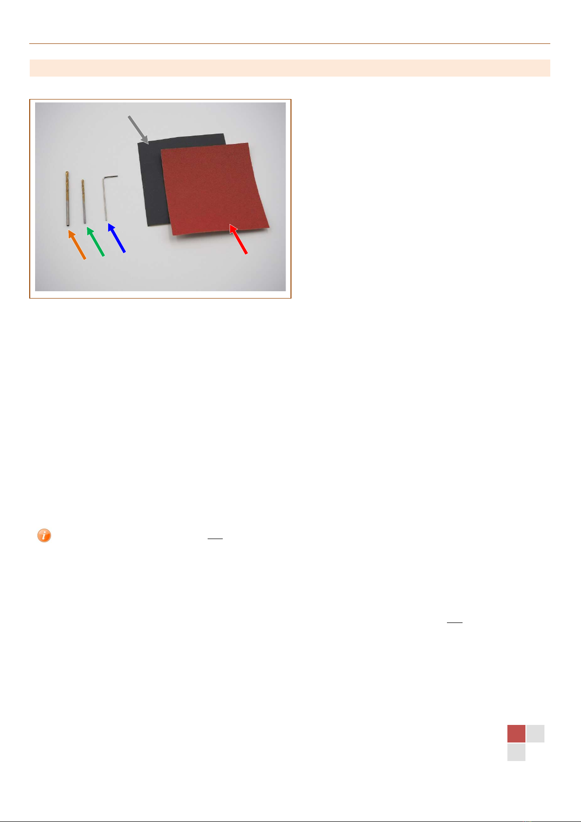
Brim For many of the printed parts a thin extra material layer is used during printing
to ensure the part does not detach from the print bed, this is called a ‘brim’. We
remove most of the brim material during post processing the components, but
any remains should be removed using a scalpel and sand paper.
Hairs/blobs During the printing process sometimes very fine ‘hairs’ or small ‘blobs’ of plastic
remain on the part. We remove most of these during post processing the
components, but any remains can be removed using a scalpel and sand paper.
M1.6, M2, M2.5, M3 These four sizes of bolts/washers/nuts are used in this kit. Bolts all have Allen
socket head unless specified otherwise.
M#cs The ‘cs’ part refers to counter sunk head.
M#button The ‘button’ part refers to button head.
M# x10mm Measurement in millimetres indicates the length of the screw thread. For
socket/button head this excludes the head, for counter sunk includes the head.
M# nylock nut The nylock nuts have the nylon insert part of the thread to resist coming loose.

INTRODUCTION
Section 1 - Page 4
STEP 3 – ICONS & SYMBOLS
Dark orange bullet Standard bullet for text/instructions
Coloured bullet Coloured bullets match text with coloured arrows/indicators on images
Arrow Images are augmented with arrows and indicators colour matched to
the bullets (noted above)
x2
Make 2 Indicates you need to repeat this step to build 2 items, or Left and Right.
Gentle Exercise care and love and gently tighten bolts/nuts!
Information Indicates some extra information or hints or options
Very Important! Highlights a very important item to take note
Check Check your assembly matches the picture

INTRODUCTION
Section 1 - Page 5
STEP 4 – LABELS GUIDE
Bags All the bags are labelled with a bag number and name and a type. Each
Bag number/name comes as a pair! A larger and smaller bag.
Bag Number Bags are numbered in the sequence and correspond exactly to each
SECTION of the assembly manual.
Bag Name Each bag is named, also correspond to the assembly section.
Bag Type Each bag in the pair contains either; Components or Hardware.
Bag Type: Components The larger bag containing the section required parts, and also contains
the smaller hardware bag.
Bag Type: Hardware The small bag contains all the required hardware such as screws, nuts,
shims, bearings etc.
Other parts Some larger parts are not bagged or labelled, but these will be
identifiable in the images! E.g.: Engine Bay!

INTRODUCTION
Section 1 - Page 6
STEP 5 – TOOLS
The kit includes:
Allen key (1x) 0.9mm (if you use your own please ensure it’s good quality and not worn, as
this can easily cause the M2 grub screws to be damaged)
2mm drill bit (1x) Used to open up any holes in the printed parts to ensure precision clearances,
e.g. the suspension hinge pin holes. Only use drill where indicated!
1.5mm drill bit (1x) Used for the scale spark plug lead wire holes and windscreen mounting holes.
Sand paper (1x) 180 grit – coarse; to clean up the printed parts edges
Sand paper (1x) 600 grit – fine; to polish any corner/edges to look pretty!
Others required:
Allen drivers 1.3mm, 1.5mm, 2.0mm & 2.5mm
Socket Driver 5.5mm (for the M3 wheel nuts)
You do not require a 4.5mm/M2 socket driver; all M2 nuts used in the kit are
inserted into the printed parts (refer to STEP 7 – TECHNIQUES for nut insertion).
Scalpel Trimming excess material off plastic parts. Optionally cutting out stickers.
Scissors Cutting out stickers.
Ball-diff grease Or similar thick silicone-based grease – used for the friction shock lubrication.
Normal ~thin shock oil NOT recommended as shocks are not sealed.
Double-sided tape Secure your ESC and Receiver….and Transponder maybe?
Optional:
Small Pliers Can be useful inserting and removing the suspension hinge pins.
Tweezers Pick up/hold smaller screw/items!

INTRODUCTION
Section 1 - Page 7
Callipers/ruler For measuring screws to ensure correct usage
STEP 6 – SPARES BAG
A selection of hardware spares has been provided in a separate bag
If you lose or damage a screw when building use one from this bag.

INTRODUCTION
Section 1 - Page 8
STEP 7 – TECHNIQUES
Always be GENTLE when tightening screws for this entire build! A little trick to keep in mind is
imagine yourself softly petting our kitten ‘Oreo’.
Nothing should be over tightened as this can damage the printed parts. As soon as you feel the
bolt bottom-out tight then STOP! ;-)
Where nuts are inserted into printed parts you can use one of three techniques;
1. Push in with your fingers.
2a. Pull the nut in by inserting the appropriate screw from the other side and tighten lightly until
the nut is pulled into the recess and seated.
2b. Alternatively pull back on the bolt with your fingers once threaded in the nut, this may be
sufficient to pull the nut into its recess.
3. Push in using an appropriate Allen driver where the hex just slides into the nut hole from the
nylon side – but be very careful and only use this method where light force is required as this
method can damage the nylock insert part if excess pushing force is used.
Table of contents
Other GP3D Motorized Toy Car manuals
Popular Motorized Toy Car manuals by other brands

Carson
Carson X8E Chassis 500409015 instruction manual

Associated Electrics
Associated Electrics Element RC Enduro owner's manual

Kyosho
Kyosho CUP Series instruction manual

REVELL
REVELL Mini Cooper Assembly instructions

Awesomatix
Awesomatix A700 Evo II instruction manual

Kyosho
Kyosho Mini-Z Racer MR-02 MM Type instruction sheet

Jamara
Jamara Porsche 911 GT3 Cup 2,4GHz instructions

Reely ROAD
Reely ROAD Cross Tiger II operating instructions

Ansmann Racing
Ansmann Racing Short Course 4wd Nitro Technical data

RC4WD
RC4WD VV-JD00066 quick start guide

MDTechShop
MDTechShop 2017-9006-06 Assembly instruction

Beyond Infinity
Beyond Infinity WONDERLANES BACKHOE 2690 owner's manual