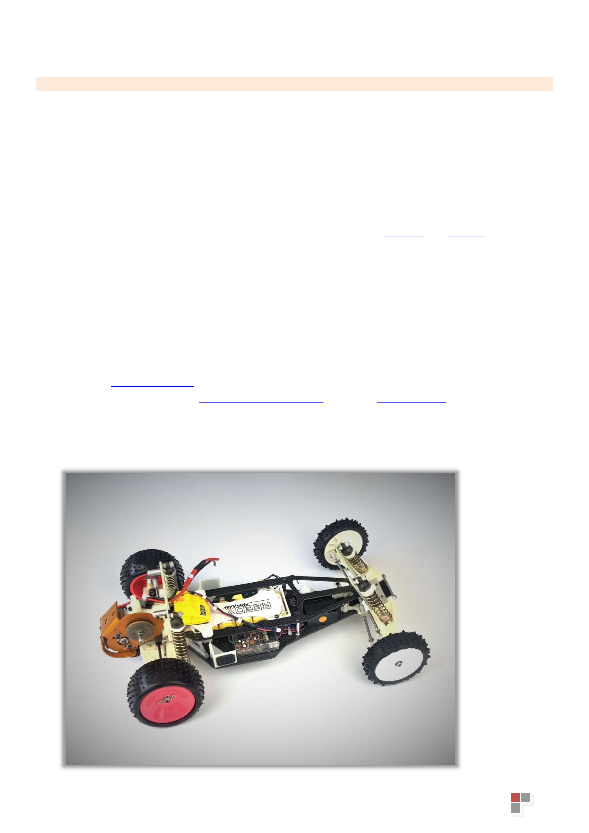
GP3D RC10GX'89 IFMAR WORLDS REPLICA CONVERSION... User manual

ASSEMBLY MANUAL
Version 1.1 ©GP3D 2022
ASSEMBLY MANUAL
RC10GX
’89 IFMAR WORLDS
REPLICA CONVERSION KIT

ASSEMBLY MANUAL
Version 1.1 ©GP3D 2022
INTRODUCTION
Firstly; A MASSIVE THANK YOU FOR YOUR SUPPORT AND PASSION!
We would like to thank you for purchasing our GP3D RC10GX ’89 IFMAR Worlds Replica
Conversion Kit. As you have purchased this kit it means you are passionate about the history of our
beloved R/C hobby and in particular one of the most iconic and revolutionary R/C cars we have
seen the prototype from Team Associated and Masaaki that took Masami Hirosaka to the 1989
IFMAR 2WD World Championship at the famed St Ives track in Australia.
GP3D and our manufacturing partners are currently looking into reproducing some of the
additionally required ‘original’ components, such as; turnbuckles, hinge pins, motor plate/guard and
rear alloy top-deck stand-offs. Therefore, please keep following our FB page and website for those
and more future developments…
The 3D printed nylon gearbox and front bulkhead parts may have a thin ‘brim’ around one face
which you remove using a scalpel and then sand edges smooth as desired, do NOT tear it off.
Some parts, including the suspension arms are printed at ~45-degree angle to maximise layer
adhesion area and balance directional strength distributions, resulting in some edges not being
‘pretty’, but these and any parts can be trimmed and sanded as desired to clean up any rough
edges/extra material as you desire.
We hope you love and enjoy building and driving your RC10GX replica, we are always available to
help and support with any questions or issues you may have. We would also love to receive
pictures of your in-progress and finished model in your chosen style and liveries that we can add to
our online Customer Gallery!
Please contact us if needed: grand.prix.3d@gmail.com OR via my FB Messenger
Information and spare parts are available in our online shop: www.GrandPrix3D.store
Our replica build, including original spec electronics and tyres!

ASSEMBLY MANUAL
Version 1.1 ©GP3D 2022
CONTENTS
ICONS & SYMBOLS ...................................................................................................................................................................................... 4
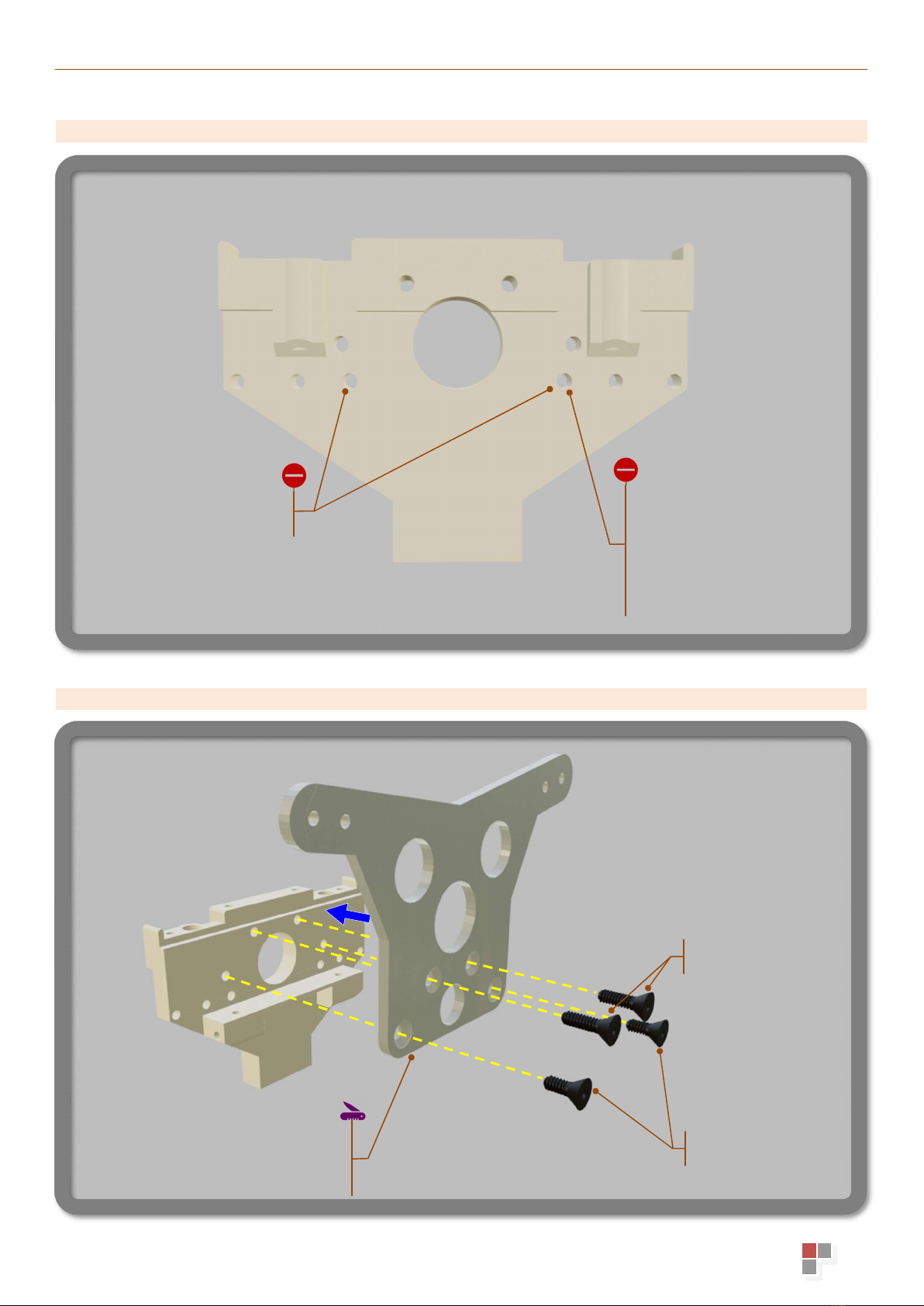
STEP 1.1 - REAR BULKHEAD ........................................................................................................................................................................ 5
STEP 1.2 - REAR SHOCK TOWER ................................................................................................................................................................. 5
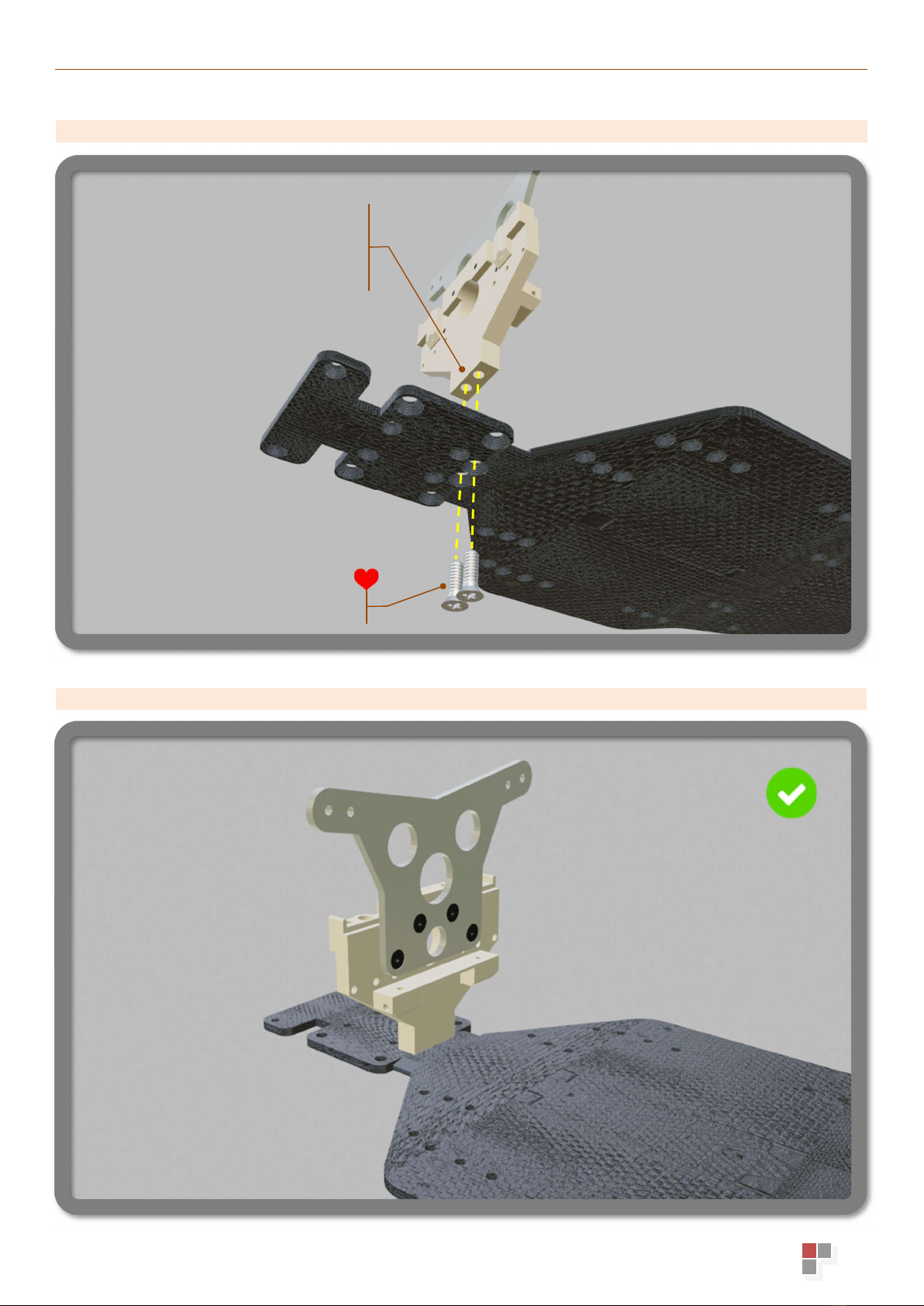
STEP 1.3 - CHASSIS ..................................................................................................................................................................................... 6
STEP 1 - COMPLETED .................................................................................................................................................................................. 6
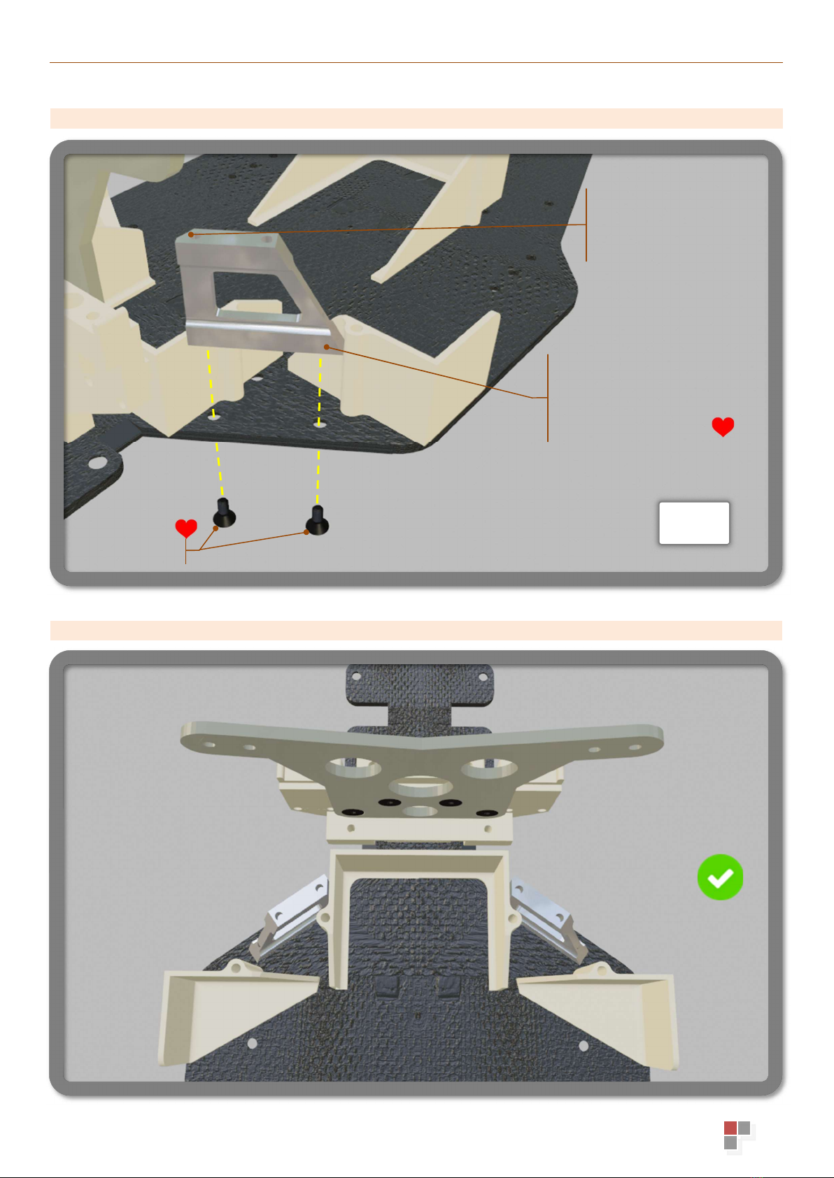
STEP 2.1 – BATTERY CUPS ......................................................................................................................................................................... 7
STEP 2.2 – SIDE BODY SUPPORTS ............................................................................................................................................................. 7
STEP 3.1 – REAR TOP-DECK SUPPORTS .................................................................................................................................................... 8
STEP 3 - COMPLETED .................................................................................................................................................................................. 8
STEP 4.1 – FRONT BULKHEAD – SHOCK TOWER ..................................................................................................................................... 9
STEP 4.2 – ATTACH FRONT BULKHEAD .................................................................................................................................................... 9
STEP 4.3 – FRONT BULKHEAD TIPS ......................................................................................................................................................... 10
STEP 4 - COMPLETED ................................................................................................................................................................................ 10
STEP 5.1 – TOP DECK & FRONT BODY POST ........................................................................................................................................... 11
STEP 5.2 – INSTALL TOP DECK ................................................................................................................................................................ 11
STEP 5.3 – NO COAST STAND-OFFS ........................................................................................................................................................ 12
STEP 5 - COMPLETED ................................................................................................................................................................................ 12
STEP 6.1 – BATTERY STRAP ..................................................................................................................................................................... 13
STEP 6.2 – OPTIONAL LONG BATTERY POSITION .................................................................................................................................. 13
STEP 6.3 – ESC SUPPORT ......................................................................................................................................................................... 14
STEP 6 - COMPLETED ................................................................................................................................................................................ 14
STEP 7.1 – REAR SUSPENSION ARMS ..................................................................................................................................................... 15
STEP 7.2 – REAR SUSPENSION ASSEMBLY COMPLETED ...................................................................................................................... 15
STEP 7.3 – INSTALL REAR SUSPENSION ARMS ...................................................................................................................................... 16
STEP 7 - COMPLETED ................................................................................................................................................................................ 16
STEP 8.1 – FRONT SUSPENSION ARMS ................................................................................................................................................... 17
STEP 8 - COMPLETED ................................................................................................................................................................................ 17
STEP 9.1 – GEARBOX ................................................................................................................................................................................ 18
STEP 9.2 – GEARBOX ASSEMBLY TIPS .................................................................................................................................................... 18
STEP 9.3 – GEARBOX INSTALLATION ...................................................................................................................................................... 19
STEP 9.4 – GEARBOX TOP PLATE ............................................................................................................................................................ 19
STEP 9.5 – GEARBOX TOP PLATE INSTALLATION .................................................................................................................................. 20
STEP 9.6 – GEARBOX CASING STAND-OFFS ........................................................................................................................................... 20
STEP 10.1 – WHEEL ADAPTERS ............................................................................................................................................................... 21
STEP 10.2 – MOTOR PLATE – CUT OUT GUIDE ....................................................................................................................................... 21
RC10GX CONVERSION KIT – COMPLETED! ............................................................................................................................................. 22

ASSEMBLY MANUAL
Version 1.1 ©GP3D 2022
ICONS & SYMBOLS
Dotted line Dotted line indicates assembly path/routing of bolts into parts
Arrow Indicates direction of part for movement to assemble
Reverse Angle Inset image showing the reverse/different angle
Item Not Included Refers to an item not included in this kit
L&R
Left & Right Indicates you need to repeat this step for Left and Right sides.
Leave loose Leave slightly loose (in some cases a future step will tighten)
Drill Drill out existing hole with provided 2mm or 1.5mm drill bit
NO Drill Do NOT drill holes (as bolt threads in)
Clean up Clean up part/edges with scalpel and/or sand paper
Gentle Exercise care and love and gently tighten!
Information Indicates some extra information or hints or options
Very Important! Highlights a very important item to take note
Check Check your assembly matches the picture

ASSEMBLY MANUAL
Version 1.1 ©GP3D 2022
STEP 1.1 - REAR BULKHEAD
STEP 1.2 - REAR SHOCK TOWER
This extreme inner
position requires the
motor plate to be
dremelled just in this
area to clear the ball cup.
Refer STEP 10.2
Use short Ball studs for
Inner Rear
Camber Link
4-40cs x5/16”
4-40cs x7/16”
Sand approx ~0.4mm off bottom
edge of tower to clear the rear
edge of top deck.

ASSEMBLY MANUAL
Version 1.1 ©GP3D 2022
STEP 1.3 - CHASSIS
STEP 1 - COMPLETED
8-32cs x1/2” Phillips
Cutting these threads will be tight,
use steel bolt only, take your time.
Light grease on thread can help.

ASSEMBLY MANUAL
Version 1.1 ©GP3D 2022
STEP 2.1 – BATTERY CUPS
STEP 2.2 – SIDE BODY SUPPORTS
4-40cs x7/16”
4-40cs x7/16”
Tip: use thin double-sided
tape under body support
to resist
rotation

ASSEMBLY MANUAL
Version 1.1 ©GP3D 2022
STEP 3.1 – REAR TOP-DECK SUPPORTS
STEP 3 - COMPLETED
Note: the angle here
indicates the right-hand
side component
4
-
40cs x5/16”
L&R
Note: this component is 3D
printed and has minimal
material around the threads
therefore be gentle.

ASSEMBLY MANUAL
Version 1.1 ©GP3D 2022
STEP 4.1 – FRONT BULKHEAD – SHOCK TOWER
STEP 4.2 – ATTACH FRONT BULKHEAD
Drill out holes slightly if
needed, so that bolt doesn’t
damage the fibreglass
4
-
40 socket x
3
/
8
”
4
-
40cs x
3
/
8
”
4
-
40cs x5/16”
Remove any
Brim material

ASSEMBLY MANUAL
Version 1.1 ©GP3D 2022
STEP 4.3 – FRONT BULKHEAD TIPS
STEP 4 - COMPLETED
Not true replica; but for racing
reliability you can use longer
4-40cs bolts and add lock
nuts to avoid loosening.
Optionally drill with 1/8” bit
and/or use a reamer until your
hinge pins slide in with small
force, they do not have to
rotate freely.

ASSEMBLY MANUAL
Version 1.1 ©GP3D 2022
STEP 5.1 – TOP DECK & FRONT BODY POST
STEP 5.2 – INSTALL TOP DECK
Note: Hole for body pin is
oriented crossways
4-40 button x3/8”
Ensure rear edge of
Top Deck slides
under bottom edge of
Rear Shock Tower
4
-
40 button x1
/4”
Note: Top deck is symmetrical top/bottom
4-40 button x3/8”
4
-
40 button x1/4”
L&R

ASSEMBLY MANUAL
Version 1.1 ©GP3D 2022
STEP 5.3 – NO COAST STAND-OFFS
STEP 5 - COMPLETED
Available Separately:
NoCoast RC alloy stand-offs
Part# NCRC-191302

ASSEMBLY MANUAL
Version 1.1 ©GP3D 2022
STEP 6.1 – BATTERY STRAP
STEP 6.2 – OPTIONAL LONG BATTERY POSITION
Mount Battery Cup
in forward position
4
-
40
socket
x
3
/
8
”
Use original Team
Associated 4-40 socket
bolts with hole through head
for split pin.
Leave 4-40 slightly
loose to ensure
battery strap can
still move
Use the longer Battery Strap component included
Full length LiPo (or position Shorty forward)

ASSEMBLY MANUAL
Version 1.1 ©GP3D 2022
STEP 6.3 – ESC SUPPORT
STEP 6 - COMPLETED
Use thick ~1mm~2mm
double-sided tape to
mount the ESC Support
Positioning of double-sided
tape pieces…
Ensure enough double-sided tape
thickness so that the ESC Support
just clears the rear battery strap
4-40 socket bolt heads.

ASSEMBLY MANUAL
Version 1.1 ©GP3D 2022
STEP 7.1 – REAR SUSPENSION ARMS
STEP 7.2 – REAR SUSPENSION ASSEMBLY COMPLETED
1/8” shim 0.020 or 0.010
Ensure smooth/free
movement of arms
Use desired shims/thickness
here to take up the gap
Your hinge pins
Drill/ream hole with 1/8” so
hinge pin becomes a press fit
Drill/ream (all 4) holes with 1/8”
so pin becomes an easy/smooth
fit as this is the suspension action
Front
thicker
Rear
thinner
Sand underside
L&R
RIGHT
Sand edges of arms to
clean up any print
roughness as desired
Use your E-clips to
secure hinge pins
RIGHT
LEFT

ASSEMBLY MANUAL
Version 1.1 ©GP3D 2022
STEP 7.3 – INSTALL REAR SUSPENSION ARMS
STEP 7 - COMPLETED
8-32cs x1/2”
Sand/Dremel the arm and/or
carbon edges, if required, to
ensure arms do not bind
(front and rear areas)
Ensure arms pivot freely

ASSEMBLY MANUAL
Version 1.1 ©GP3D 2022
STEP 8.1 – FRONT SUSPENSION ARMS
STEP 8 - COMPLETED
L&R
Use 1/8” shims as desired;
front/in-between/rear, to
take up the gaps
Your hinge pins
Drill/ream holes with 1/8” so
hinge pin becomes a press fit
Drill/ream (all 4) holes with 1/8”
so pin becomes an easy/smooth
fit as this is the suspension action
Use your E-clips to
secure hinge pins
Ensure arms pivot freely
Sand edges of arms to
clean up any print
roughness as desired

ASSEMBLY MANUAL
Version 1.1 ©GP3D 2022
STEP 9.1 – GEARBOX
STEP 9.2 – GEARBOX ASSEMBLY TIPS
Press output ring into
recess in Gearbox casing.
Make sure is fully seated
by pressing assembly
against flat surface.
Do NOT drill out hole
in casing as
4-40 x3/8” threads in
Your bearing
Shim your top layshaft on left side here, to move it towards the
right as desired, ensuring a small amount of end play is attained.
This will ensure slipper plates clear ends of your 4-40 x1”
gearbox bolts
Sand faces and bottom
surface of casing
before assembly
L&R
4-40 socket x3/8”
Only use 3x of your 4-40 x1”
bolts to mount gearbox to
your motor plate.
Tip: If needed, add 1/8” shims
under bolt heads if needed to
avoid bolt tip protruding past
motor plate into slipper.
2
1
3
Remove any
Brim
material

ASSEMBLY MANUAL
Version 1.1 ©GP3D 2022
STEP 9.3 – GEARBOX INSTALLATION
STEP 9.4 – GEARBOX TOP PLATE
8-32cs x1/2”
Note:
Counter sink underside
Rear Suspension
omitted in this view
for clarity!

ASSEMBLY MANUAL
Version 1.1 ©GP3D 2022
STEP 9.5 – GEARBOX TOP PLATE INSTALLATION
STEP 9.6 – GEARBOX CASING STAND-OFFS
4-40cs x3/16 or 1/4”
For your motor guard
4
-
40 socket x3/8”
Rear Suspension
omitted in this view
for clarity!
3x Motor Plate Stand-offs
Table of contents
Other GP3D Motorized Toy Car manuals
Popular Motorized Toy Car manuals by other brands

Jamara
Jamara Concrete mixer MercedesBenz Arocs Instruction

Team Losi
Team Losi XXX-NT Adam Drake Edition owner's manual

Harbor Freight Tools
Harbor Freight Tools 62527 owner's manual

Hamdol
Hamdol T1 user manual

Kyosho
Kyosho MINI-Z Racer MR-02 RM Type instruction sheet

Reely
Reely 1:8 GP Monstertruck EarthCrusher RtR Service manual

Mercedes-Benz
Mercedes-Benz G 63 AMG Owner's manual with assembly instructions

Hornby
Hornby AIRFIX Bedford QLD manual

Carisma
Carisma SCALE ADVENTURE Series User manual & setup guide

Tameo Kits
Tameo Kits Lotus Ford 79 manual

Chi Lok Bo Toys
Chi Lok Bo Toys BMW 4 Coupe Series Assembly instructions and operating manual

HPI Racing
HPI Racing Savage XL instruction manual