GPX ZS194MQ User manual

Page 131
GPX 450 FSE
Engine manual
ZS194MQ (NC450)
send
move
machine
dimension
build
handbook
Chongqing Zongshen Engine Manufacturing Co., Ltd.
Prepare: Proofread: Review: Approve:
Repair of cylinder head assembly

Page 231
1. Troubleshooting
2. Maintenance Instructions
3. Removal of the cylinder head cover
4. Disassembly of the cylinder head
5. Decomposition of the cylinder head
6. Inspection of valve and valve spring
7. Rocker arm inspection
8. Inspection of cylinder head
9. Assembly of cylinder head
10. Installation of cylinder head
11. Installation of cylinder head cover
Troubleshooting
Maintenance notice
Maintenance parameters of each component
project
Standard value mm
Maintenance limit
mm
Axial clearance between rocker arm and cylinder head
rocker arm
0.05~0.3
0.5
Radial clearance between rocker arm and rocker arm
shaft
0.016~0.045
0.08
valve spring free length
Outside: 39.6 Inside:
37.7
Outside: 39.75 Inside:
36.85
valve clearance
0.06~0.08
------
Camshaft base circle runout
0.02
0.04
Low cylinder pressure:
1、valve
Incorrect valve clearance adjustment
Poor valve seal
Incorrect gas timing
Broken valve spring
2、cylinder head
The spark plug is not tightly connected to the
cylinder head
Damaged cylinder head gasket
Cracks or blisters in the cylinder head
3、Cylinders, Pistons, Piston Rings
Excessive or broken piston ring clearance
Cylinder block
Exhaust with black smoke
1、valve guide wear
2、Oil shield leaking or damaged
3、Cylinder head gasket leakage
4、Excessive piston ring clearance
Heat engine noise is too loud or abnormal
1、Incorrect valve adjustment
2、Stuck valve or broken valve spring
3、Excessive wear on the upper rocker arm
4、Incorrect gas timing
5. Camshaft wear
6. The pressure relief valve is broken
project
Standard value mm
Maintenance limit
mm
valve
valve stem outer
diameter
intake
φ4.972~φ4.987
φ4.96
exhaust
φ4.96~φ4.975
φ4.94
Valve guide inner
diameter
intake
φ5.005~φ5.015
φ5.035
exhaust
φ5.005~φ5.015
φ5.035
Valve stem and guide
clearance
intake
0.018~0.043
0.07
exhaust
0.35~0.055
0.08
valve seal width
1.5
----
cylinder head
Flatness
0.04
0.05
Valve seat working face width
0.8
----

Page 331
Disassembly and maintenance of cylinder head assembly
1. Cylinder head assembly drawing . For this drawing please see the bottom of this document
For a key to these diagrams please visit the bottom of this document.
For the key to these diagrams see the end of this document
1
1
12
13
12
3
14
1
5
16
17
4
5
6
7
8
9
1
7
8
9
1
6

Page 431
Removal of cylinder head cover
1. Remove the 2 NC450 cylinder head covers
from the cylinder head cover and fix them
Bolts (special-shaped M6×29.7), 2 NC450
cylinder head covers are fixed
Bolts (special-shaped M6× 50.7 );
4. Remove the cylinder head cover;
Disassembly of the cylinder head
1. Remove the two M6×20 bolts that fasten
the tensioner,
Then remove the tensioner assembly and the
tensioner gasket;
2. Turn the timing driven sprocket to the
engine timing position:
Arrow mark of timing driven sprocket and
cylinder head timing mark
align;
3. Remove the bolt M6×16 and the flat
washer, and remove the NC
450 pressure reducing valve throw block
combination;
4. Remove 2 bolts M6×10 and take off the
timing driven chain
Tensioner
combination
boltM6 ×
20
Arrow marking of
timing driven
sprocket
cylinder head
timing mark
boltM6×40
bolt AB(M10×152)
Bolt M6×16
Bolt M6×10

Page 531
wheel, remove the timing chain set on the timing driven
sprocket ;
5. Remove the M6×40 bolts connecting the
cylinder head and the cylinder block;
6. Remove 4 NC450 cylinder stud bolts AB (M
10×152), then remove 4 flat washers;
7. Remove the cylinder head;
Disassembly of the
cylinder head
1. Remove 1 screw M6×12, and remove
the NC450 camshaft pressure plate;
2. Remove the camshaft;
3. Remove the two NC250 rocker shafts on the
cylinder head cover for positioning
Bolt M14×1,
4. Remove 2 bolts M6×18 and 2 flat washers
lock up;
4. Remove the intake and exhaust rocker
arm shafts, and remove the intake and exhaust
rocker arms;
5. Press down the valve spring with the
valve remover and remove the valve lock clip;
then loosen the valve remover and remove the
valve spring seat, valve spring and valve.
NC250Rocker shaft
positioning bolt
Bolt M6×18

Page 631
Notice:
1. In order to prevent the permanent
deformation of the valve spring, the valve
spring cannot be compressed excessively,
and only the valve lock clip can be
removed;
2. All the removed parts should be
marked to ensure that the original assembly
position is reached during assembly.
Inspection of valves and valve
springs
1. Check whether the valve is bent or the
valve stem has abnormal wear, and measure the
outer diameter of the valve stem. Repair limit:
Air intake: φ4.96mm
Exhaust: φ4.94mm
2. The width maintenance limit of the
contact surface: 1.5mm
Notice:
If the valve contact surface is rough, the
abrasion is uneven or the contact with the
valve seat is abnormal, and the sealing
performance cannot be guaranteed, the
valve should be replaced.
3. Check whether the valve spring is abnormally worn,
and the measurement is free
length. Repair limit:
Outer spring: 39.75m
Inner spring: 36.85mm
Inspection of rocker arm and rocker
arm shaft
Check the rocker arm for abnormal wear, the axial
direction of the rocker arm roller
Whether the clearance and rocker rollers have eccentric
wear, such as wear, damage
If the phenomenon is serious or the axial clearance of the
rocker roller is too large, more
Replace with a new rocker arm.
Inspection of Camshaft Components

Page 731
1. Check whether the surface of the camshaft is
worn or damaged
And whether the camshaft bearing rotates flexibly, such
as serious wear
Or the bearing rotates with the phenomenon of hairpin,
then the cam should be replaced with a new one.
shaft parts;
Inspection of the cylinder head
1. Check whether the sealing of the cylinder
head is good. If the sealing of the cylinder head
is poor, a new cylinder head or valve should be
replaced;
2. Check whether the cylinder head is
deformed, and check the flatness of the cylinder
head with a knife edge ruler and a feeler gauge.
燃烧室检漏测试:充气 0.3Mpa,泄漏量≤
6000pa/10 秒。
检测参数:充气时间 5S、平衡时间 3S、检
测 时 间 2S 、 放 气 时 间 0.5S 、 检 压 上 限
320Kpa、检压下限 290Kpa、判定值 1.2Kpa。
Check cylinder
head flatness

Page 831
Assembly of the cylinder
head
1. Install the valve spring lower seat
(3) and the oil shield (4) to the valve
guide;
2. After applying a small amount of
lubricating oil to the intake valve rod (1)
and exhaust valve rod (2), install the
valve guide, install the valve outer
spring (5), the valve inner spring (6), and
the valve spring upper seat ( 7) and valve
lock clip (8);
3. Use the valve remover to depress the
valve spring, and then install the valve
lock clip into the valve spring seat;
Notice:
To prevent permanent deformation of the
valve spring, do not compress the spring too
much to fit the valve lock clip.
4. Check whether the valve lock clip is in
place;
5. Carry out the air tightness test on the
assembled cylinder head combination. If the air
tightness test of the cylinder head combination is
qualified, the next step can be performed
(assemble according to the cylinder head
composition diagram);
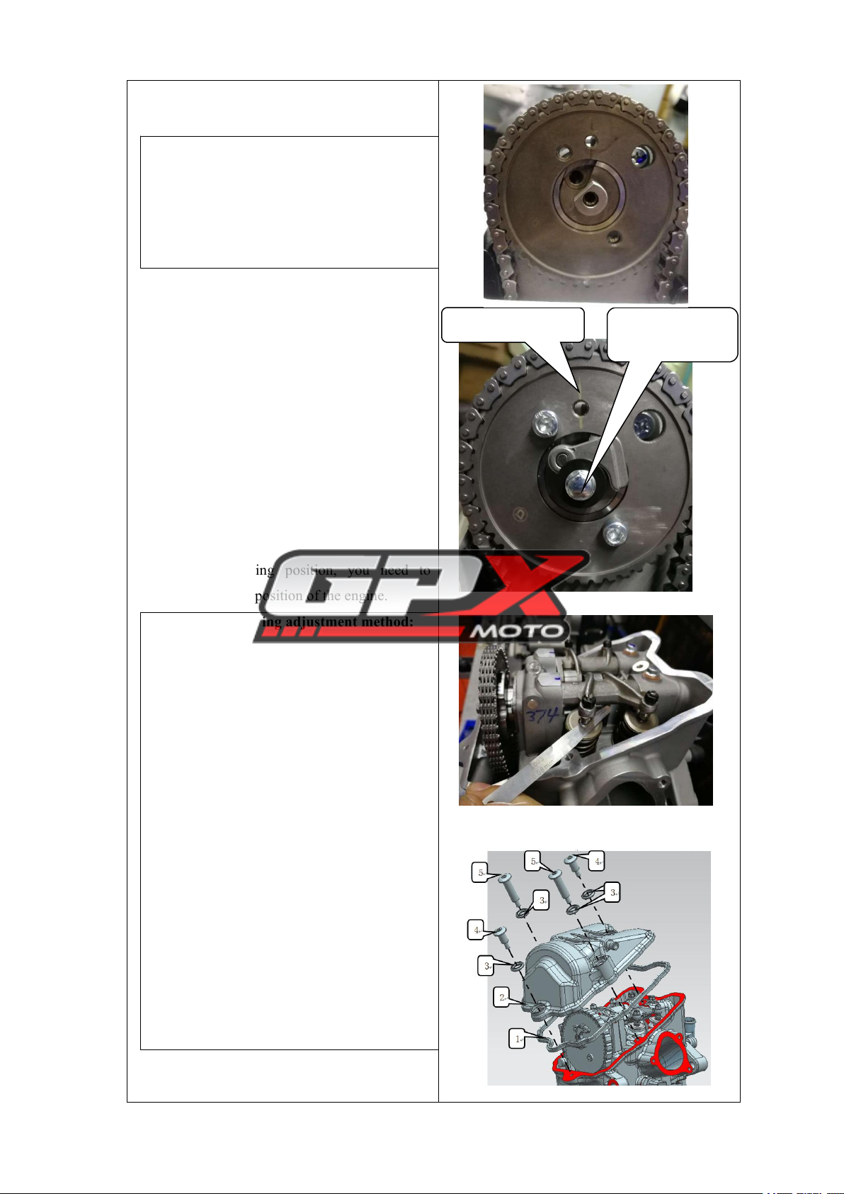
6. Take the assembled camshaft parts,
apply grease on the surface of the small
journal, assemble it at the position of the
camshaft hole of the cylinder head, take
the screw M6 ×12, insert it into the camshaft
pressure plate hole, assemble it at the designated
position of the cylinder head, and fasten;
7. Take the intake rocker arm and the
valve rocker arm shaft respectively, and
assemble them at the position of the
cylinder head intake rocker arm shaft
This side is the cutting edge of the rocker
arm shaft. When assembling the rocker arm
shaft, this side should face the top of the
cylinder head cover
M6×18

Page 931
hole;
8. Take the exhaust rocker arm and
valve rocker arm shaft respectively, and
assemble them at the position of the
cylinder head exhaust rocker arm shaft
hole;
9. Use a flat-blade screwdriver to
turn the rocker arm shaft of the intake and
exhaust rocker arm to align the threaded
hole of the rocker arm shaft with the
position of the smooth hole of the
dependent cylinder head.
10. Take GB16674 small plate bolts M6×18
and put flat washers on them, assemble them at
the threads of the inlet and outlet rocker arm
shafts, and fasten them.
11. Take the NC250 rocker shaft
positioning bolt M14×1, insert it into
the O-ring, and assemble it at the designated
threaded hole position of the cylinder head.
Notice:
1. When installing the rocker arm shaft, the
side of the rocker arm shaft with the trimmed
edge should face the top of the cylinder head
cover.
2. After the cylinder head cover is installed,
turn the rocker arm. The rocker arm should
rotate flexibly without sticking.
Installation of the cylinder
head
1. Remove the old cylinder head gasket,
install the new cylinder head gasket (2), and then
install the positioning pin (3);
2. Install the cylinder head to the cylinder
block, then put the A and B bolt nut washers (5 )
on the NC450 cylinder stud bolt AB (6 ) , and
then install the NC450 cylinder stud bolt AB
1
2
3
3
4
5
6
5
66
55
7
ZS96large
aperture cover
NC250Rocker shaft positioning plate
bolt
NC250Magneto
RotorTiming Marks
NC450Left front
cover timing mark

Page 1031
(6 ) to the cylinder head , in the connecting hole
of the cylinder body and fasten it;
Notice:
1. The cylinder head gasket must be replaced
with a new one;
2. Tightening torque of bolts A and B:
55~60N.m.
3. Install the M6×25 bolts (7) to the cylinder block
and box
Install the bolts (4) of M6×40
into the connecting hole of the cylinder head and
cylinder block and tighten.
Tightening torque: 11~13N.m.
4. Install the timing driven sprocket and
timing chain on the camshaft, and then check
whether the engine is in the timing position. If it
is not in the timing position, you need to
re-adjust the timing position of the engine.
NC450 engine timing adjustment method:
(1) Remove the large viewing hole cover of
the left front cover and the bolts of the NC250
rocker shaft positioning plate;
(2) Rotate the NC250 magneto lock nut with a
special tool, and at the same time pass the
bolt hole of the rocker shaft positioning plate
on the left front cover
Observe whether the timing mark "one" on
the magneto rotor is aligned with the timing
mark on the left front cover;
(3) After the above timing marks are aligned,
pay attention to observe whether the timing
mark on the timing driven sprocket is on the
same line as the cylinder head timing mark;
The engine is in the correct timing position
only if (2)(3) are satisfied at the same time.
After adjusting the timing position,
assemble the large sight hole cover and the bolts
Timing driven sprocket
timing mark
NC450cylinder head
timing mark

Page 1131
of the NC250 rocker shaft positioning plate to the
left front cover;
6. Take 2 pieces of bolts M6 ×10, and
fasten the NC450 timing driven sprocket on the
camshaft; take 1 piece of the camshaft
pressure reducing valve throwing block
combination and the pressure reducing
valve return spring, and throw the
pressure reducing valve block The
combination and pressure reducing valve
return spring is assembled on the camshaft
through the timing driven sprocket; take
the bolt M6 × 16 and put it into the flat
washer, install it into the corresponding
threaded hole of the camshaft, and fasten it.
Tightening torque: 11 to 13N ·m.
7. Adjust the gap between the intake and
exhaust valves, the gap value of the valve: 0.07
±0.01mm

Page 1231
Installation of the cylinder head cover
1. Take the NC450 cylinder head cover
sealing ring (1) and the Derbi125 head cover bolt
buffer washer (3), and assemble them on the
designated position of the NC450 cylinder head
cover (2).
2. Take 2 pieces of NC450 cylinder head
cover fixing bolts (4) and 2 pieces of NC450
cylinder head cover fixing bolts (5), assemble the
NC450 cylinder head cover (2) on the cylinder
head, and fasten them.
Tightening torque: 11~13N ·.m .

Page 1331
Cylinder block and piston repair
1. Maintenance Instructions
2. Disassembly of the cylinder
3. Cylinder inspection
4. Disassembly of the piston
5. Inspection of piston and piston ring
6. Installation of piston ring 7. Installation of piston
8. Installation of the cylinder
Maintenance notice
Notes :
●The cylinder head lubricating oil is supplied to the cylinder head through the small oil
hole next to the AB bolt on the left body of the engine. Before installing the cylinder,
make sure that the small oil hole next to the AB bolt on the left body is unobstructed.
Do not install the solid positioning pin of the cylinder block into the oil passage hole.
Maintenance parameters of each component
project
Standard value mm
Maintenance limit
mm
cylinder
Cylinder bore
φ94.5~φ94.52
φ94.528
Out of roundness
0.05
0.01
Cylinder surface flatness
0.03
0.05
piston
piston ring
live
plugged
Piston outside diameter
φ94.45~φ94.46
φ94.43
Piston pin hole inner diameter
φ20.001~φ20.006
φ20.015
Piston pin and piston pin hole clearance
0.001~0.012
0.025
Piston Ring Closed
Gap
Top
Ring/Second
Ring
0.2~0.35
0.5
oil ring
0.2~0.7
1.4
Piston ring and piston
ring groove clearance
top ring
0.03~0.07
0.08
second ring
0.02~0.06
0.08
Cylinder to Piston Clearance
0.035~0.065
0.07
Piston pin outer diameter
φ19.994~φ20
φ19.99
connecting
rod small end
the inside diameter of
φ20.015~φ20.025
φ20.04
Small end of connecting rod and piston
pin clearance
0.015~0.03
0.05

Page 1431
Assembly drawing
1. NC450 piston
2. NC450 piston pin retaining
ring
3. NC450 piston ring assembly
4. NC450 piston pin
5. NC450 cylinder block parts
6. NC450 cylinder block gasket
7. Cylindrical pin φ6×12
8. NC450 chain guide plate
combination
9. NC450 timing chain
combination

Page 1531
Disassembly of the cylinder
Remove the chain guide plate, remove the two
cylinder blocks and the box connecting bolts M6 ×
25, and remove the cylinder block.
Use a scraper to scrape off the remaining gasket
on the cylinder surface.
Cylinder block inspection
1. Check whether the cylinder block is worn or
damaged.
2. When measuring the inner diameter of the
cylinder, three positions should be measured, namely
the top, middle and bottom of the piston stroke, and
two directions at right angles to each other should be
measured during measurement.
Maintenance limit: φ94.528mm
boltM6×25
chain guide

Page 1631
Disassembly of the piston
Use needle-nose pliers to remove the piston pin
retaining ring and remove the piston pin and piston.
Notice:
When removing the piston pin retaining ring,
do not drop the retaining ring into the
crankcase
Inspection of pistons and piston
rings
1. Remove the piston ring;
2. Measure the gap between the piston ring and
the groove of the piston ring, and the maintenance
limit value:
The first ring: 0.08mm
Second Ring: 0.08 mm
Oil ring: 0.08 mm
3. Check whether the piston is worn or cracked,
and whether the groove of the piston ring is worn.
4. Insert the piston ring into the cylinder, and then
measure the closed gap of the piston ring.
Repair limit:
The first ring: 0.5mm
Second ring: 0.5mm
Oil ring: 1.4 mm

Page 1731

Page 1831
5. Measure the outer diameter at a height of 7 mm
from the piston skirt
Maintenance limit: φφ94.43 mm
6. Calculate the gap between the cylinder and the
piston.
Maintenance limit: 0.1mm
7. Measure the outer diameter of the piston pin
Maintenance limit: φ19.99 mm
8. Calculate the clearance between the piston and
the piston pin
Service limit: 0.025 mm
Piston Ring Installation
1. Thoroughly clean the groove of the piston ring;
2. Install the piston ring;
Notice:
1、During installation, the piston and piston
rings should be protected from damage;
2、When installing the piston ring, do not
install the first ring and the second ring
wrongly .
The marked side of the first and second rings
faces the top of the piston ;
3、After installation, the piston ring should
rotate flexibly .
3. The gap between each ring in the oil ring
should be matched with the gap of the spacer ring;
when installing the oil ring, the spacer ring should be

Page 1931
installed first, and then the side guide rails should be
installed.

Page 2031
Piston installation
Install the piston, piston pin and new piston pin
retainer.
Notice:
1. When installing the piston, the side
marked with " " should face the exhaust side of
the engine ;
2. The opening of the end clearance of the
piston pin retaining ring should face
downward;
3. If the piston pin retaining ring is seriously
deformed, it must be replaced with a new
retaining ring;
4. Do not let the piston pin retaining ring fall
into the crankcase .
Installation of the cylinder block
1. Install cylinder block positioning pins and new
cylinder block gaskets;
2. Apply a layer of oil evenly on the surface of the
cylinder block, piston and piston ring ;
3. First stagger the openings between the piston
rings by 120°, and then gently assemble the cylinder
block in place ;
4. Assemble the chain guide plate in place.
NOTE: When installing the cylinder block,
avoid damaging the piston rings.
When assembling the piston, the side
marked with "" should face the
exhaust side of the engine
This manual suits for next models
1
Table of contents
Popular Engine manuals by other brands

potenza
potenza 60 user guide

DLE
DLE DLE120-T4 user manual

Schartec
Schartec Tube FE Installation and operating instructions

3T-Components
3T-Components 3T-MOTORS 3T45-E Installation & operating instructions

PYD Electrobombas
PYD Electrobombas MOTOR 4 Series Instruction manual and maintenance

Crestron
Crestron DGE-100 Supplemental guide