FULL MOTION FLAT PANEL TV MOUNT FOR 19-50”TELEVISIONS
User’s Guide for Model No. TM45 v1382-01
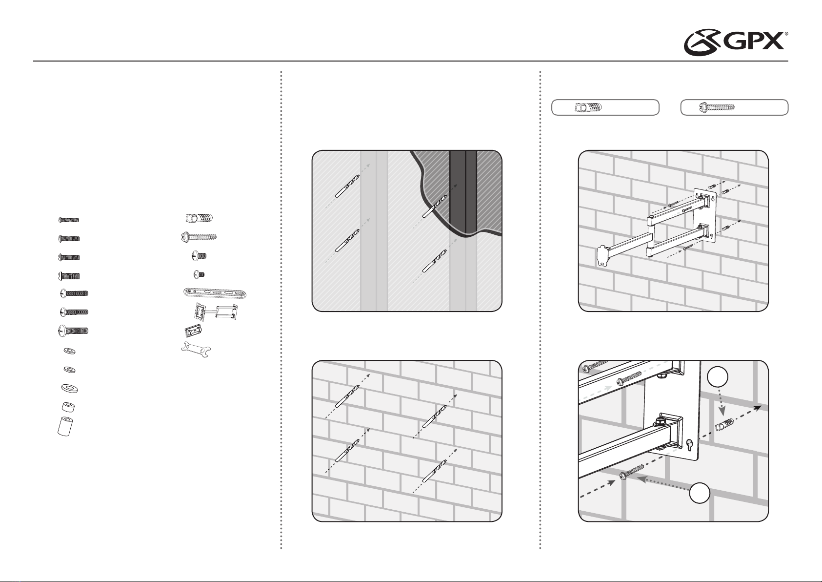
• Concrete/Brick wall shown
• Use a 3/8” or 10mm drill bit
• Cutaway of drywall with studs shown behind. Use a stud nder to locate
studs. ONLY DRILL INTO STUDS!!
• Use a 5/32” drill bit
STEP 1
Pre-drill Holes for Articulating Swing Arm
• Drill 4 holes for the Swing Arm to attach to the wall, using exact
measurements based on where you want to mount the Articulating
Swing Arm. Only drill into a solid wall, or studs (behind drywall). DO NOT
DRILL AND HANG THE BASE PLATE ON DRYWALL OR SHEETROCK.
It is not strong enough to support a TV and will cause damage.
WARNINGS
• The wall mounted parts of the TV mount must be rmly attached to a
concrete/brick/solid wood wall, or wall studs behind drywall.
• Tighten screws so that the wall plate is rmly attached, but do not
overtighten. Overtightening can damage the screws and increase the
chances of failure.
• Do not remove or loosen any screws until they are no longer engaged
with the mount. Doing so may cause the screen to fall.
• It is highly recommended to have this mount professionally installed.
• Supports VESA up to 400 x 400mm (100 x 100mm for 19”TVs).
• This mount is designed to hold a maximum of 66 lbs (30 kg).
TOOLS
The following tools are recommended for this installation:
• Drill
• 5/32” drill bit for drywall
• 3/8” or 10mm drill bit for concrete
• Stud nder
• Phillips screwdriver
PARTS
G x4
M8x25
x4F M6x25
x4E M5x25
M x4
Ø10x50
N x4
M6x50
x1S Mag Level
x4H Ø5
x4I Ø6
x4J Ø8
Ø15xØ8x4.5 x4K
Ø15xØ8x15 x4L
x4C M6x15
x4D M8x15
B x4
M5x15
M4x15
G x4
M8x25
x4F M6x25
x4E M5x25
M x4
Ø10x50
N x4
M6x50
x1S Mag Level
x1R
x4Q
O x4
M8x8
x4P M6x8
Ø15xØ8x4.5 x4K
Ø15xØ8x15 x4L
x4C M6x15
x4D M8x15
B x4
M5x15
A x4
M4x15
x1T Wrench
Note: Parts A-L are used to attach
your TV to the brackets in Step 4,
but you will not need all of them.
Find and use the set that best ts
your specic TV.
STEP 2
Attach Articulating Swing Arm to Wall
• Attach the articulating swing arm to the wall. Use the included level to
ensure the arm is correctly aligned and square.
• Insert the four wall anchors into the holes drilled in Step 1, then screw
the base plate rmly to the wall with the supplied screws.
G x4
M8x25
x4F M6x25
x4E M5x25
M x4
Ø10x50
N x4
M6x50
x1S Mag Level
x4H Ø5
x4I Ø6
x4J Ø8
x1R
x4Q
O x4
M8x8
x4P M6x8
Ø15xØ8x4.5 x4K
Ø15xØ8x15 x4L
x4C M6x15
x4D M8x15
B x4
M5x15
A x4
M4x15
x1T Wrench
G x4
M8x25
x4F M6x25
x4E M5x25
M x4
Ø10x50
N x4
M6x50
x1S Mag Level
x4H Ø5
x4I Ø6
x4J Ø8
x1R
x4Q
O x4
M8x8
x4P M6x8
Ø15xØ8x4.5 x4K
Ø15xØ8x15 x4L
x4C M6x15
x4D M8x15
B x4
M5x15
A x4
M4x15
x1T Wrench
N
M


