manuals.online logo
Brands
  1. Home
  2. •
  3. Brands
  4. •
  5. Graco
  6. •
  7. Paint Sprayer
  8. •
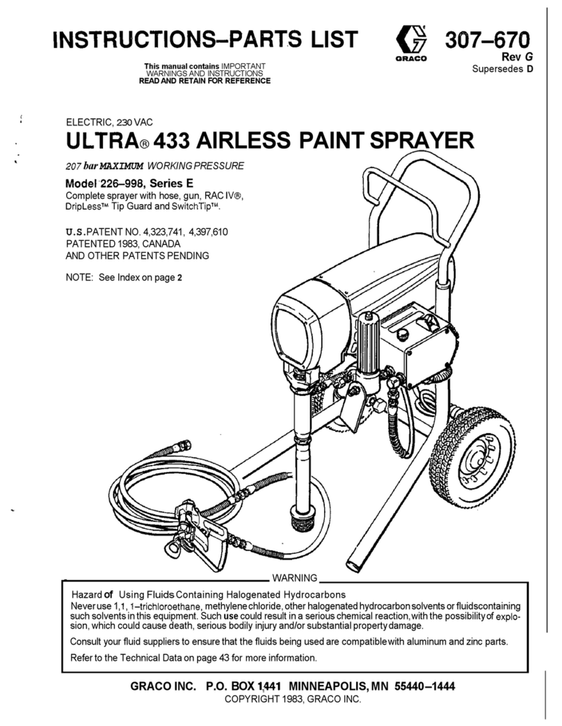
  9. Graco HYDRA-MASTIC 206-718 Operation manual

Graco HYDRA-MASTIC 206-718 Operation manual

This manual suits for next models

2

Other Graco Paint Sprayer manuals

Graco 16H960 Guide

Graco

Graco 16H960 Guide

Graco TexSpray Compact HP Operation manual

Graco

Graco TexSpray Compact HP Operation manual

Graco GM3500 SPRAYER 231-078 Datasheet

Graco

Graco GM3500 SPRAYER 231-078 Datasheet

Graco Reactor 2 E-XP2 Instruction Manual

Graco

Graco Reactor 2 E-XP2 Instruction Manual

Graco PT2500 User manual

Graco

Graco PT2500 User manual

Graco 16N661 Use and care manual

Graco

Graco 16N661 Use and care manual

Graco UNICARB Pro AA4500 Operation manual

Graco

Graco UNICARB Pro AA4500 Operation manual

Graco PRO Delta Spray 240-385 Operation manual

Graco

Graco PRO Delta Spray 240-385 Operation manual

Graco 248650 Use and care manual

Graco

Graco 248650 Use and care manual

Graco 309740 User manual

Graco

Graco 309740 User manual

Graco 237-421 Operation manual

Graco

Graco 237-421 Operation manual

Graco 238377 User manual

Graco

Graco 238377 User manual

Graco QuickShot 20B473 Operating instructions

Graco

Graco QuickShot 20B473 Operating instructions

Graco 231409 Operation manual

Graco

Graco 231409 Operation manual

Graco FinishPro HVLP 7.0 Use and care manual

Graco

Graco FinishPro HVLP 7.0 Use and care manual

Graco 980 User manual

Graco

Graco 980 User manual

Graco 395 233960 Operating instructions

Graco

Graco 395 233960 Operating instructions

Graco 311001G Datasheet

Graco

Graco 311001G Datasheet

Graco 222973 Operation manual

Graco

Graco 222973 Operation manual

Graco 310645K Use and care manual

Graco

Graco 310645K Use and care manual

Graco Contractor II User manual

Graco

Graco Contractor II User manual

Graco GX-7A Quick start guide

Graco

Graco GX-7A Quick start guide

Graco UNICARB Pro AA4500 User manual

Graco

Graco UNICARB Pro AA4500 User manual

Graco 232443 Operation manual

Graco

Graco 232443 Operation manual

Popular Paint Sprayer manuals by other brands

Idex Akron Brass FS100 quick start guide

Idex

Idex Akron Brass FS100 quick start guide

mbp TEL 15BS instructions

mbp

mbp TEL 15BS instructions

Solo 425 Classic Original instructions

Solo

Solo 425 Classic Original instructions

WAGNER AirCoat GM 4100 AC operating manual

WAGNER

WAGNER AirCoat GM 4100 AC operating manual

Titan MultiFinish 440 owner's manual

Titan

Titan MultiFinish 440 owner's manual

SNOWJOE Sunjoe 24V-GS-LTW-RM Operator's manual

SNOWJOE

SNOWJOE Sunjoe 24V-GS-LTW-RM Operator's manual

Walther FSP-01 Assembly instructions

Walther

Walther FSP-01 Assembly instructions

Fimco LG-4-3-1 owner's manual

Fimco

Fimco LG-4-3-1 owner's manual

Nordson MicroMax 2 manual

Nordson

Nordson MicroMax 2 manual

Bonide 051 Operation and service instructions

Bonide

Bonide 051 Operation and service instructions

zogics Z-DAS instruction manual

zogics

zogics Z-DAS instruction manual

KISANKRAFT KK-KBS-165 Operation manual

KISANKRAFT

KISANKRAFT KK-KBS-165 Operation manual

Matrix SG 650 Translation of the original instructions

Matrix

Matrix SG 650 Translation of the original instructions

paasche VV Instructions and parts list

paasche

paasche VV Instructions and parts list

Carlisle DeVilbiss JGA-510 Service manual

Carlisle

Carlisle DeVilbiss JGA-510 Service manual

Gardena 11120 Operator's manual

Gardena

Gardena 11120 Operator's manual

DeVilbiss LUNA2i Operation manual

DeVilbiss

DeVilbiss LUNA2i Operation manual

WAGNER W 125 manual

WAGNER

WAGNER W 125 manual

manuals.online logo
manuals.online logoBrands
  • About & Mission
  • Contact us
  • Privacy Policy
  • Terms and Conditions

Copyright 2025 Manuals.Online. All Rights Reserved.

306–863
Rev. G
Supersedes Rev. F
INSTRUCTIONS-PARTS
LIST
INSTRUCTIONS
This
manual contains important
warnings and information.
READ AND KEEP FOR REFERENCE.
HYDRA-MASTIC
SPRA
Y GUN
3000
psi (210 bar) MAXIMUM WORKING PRESSURE
U.S.
Patent No. 3,362,644
Model 206–718, Series M
Standard Gun with Dif
fuser
Model 207–300, Series J
Standard Gun without Dif
fuser
Model 207–127, Series K
Pole Gun with Dif
fuser and 37.5” (950 mm) Extension
NOTE:
Spray tip not included; order separately
.
EXTENSION KIT 207–049
Adds
37.5” (950 mm) Extension to Standard Gun
206–718 or 207–300
GRACO INC. P.O. BOX 1441
MINNEAPOLIS, MN
55440–1441
Graco
Inc. is registered to I.S. EN ISO 9001
0956
0955
Models
206–718 & 207–300
Model 207–127

Table
of Contents
Warnings 2.
. . . . . . . . . . . . . . . . . . . . . . . . . . . . . . . . . . . . .
Installation 5
. . . . . . . . . . . . . . . . . . . . . . . . . . . . . . . . . . . .
Operation
6.
. . . . . . . . . . . . . . . . . . . . . . . . . . . . . . . . . . . .
Troubleshooting
8.
. . . . . . . . . . . . . . . . . . . . . . . . . . . . . .
Service
8.
. . . . . . . . . . . . . . . . . . . . . . . . . . . . . . . . . . . . . .
Model
206–718
11.
. . . . . . . . . . . . . . . . . . . . . . . . . . . . .
Model
207–300
12.
. . . . . . . . . . . . . . . . . . . . . . . . . . . . .
Model
207–127
13.
. . . . . . . . . . . . . . . . . . . . . . . . . . . . .
Extension
Kit 207–049
14.
. . . . . . . . . . . . . . . . . . . . . . . .
Accessories 15
. . . . . . . . . . . . . . . . . . . . . . . . . . . . . . . . . .
Technical
Data
15.
. . . . . . . . . . . . . . . . . . . . . . . . . . . . . . .
Graco
W
arranty and Disclaimers
16.
. . . . . . . . . . . . . . .
Symbols
Warning Symbol
WARNING
his
symbol alerts you to the possibility of serious
injury or death if you do not follow the instructions.
Caution Symbol
CAUTION
This
symbol alerts you to the possibility of damage to
or destruction of equipment if you do not follow the
instructions.
FIRE AND EXPLOSION HAZARD
Improper
grounding, poor ventilation, open flames or sparks can cause a hazardous condition and
result in a fire or explosion and serious injury
.

If there is any static sparking or you feel an electric shock while using this equipment,
stop
spraying immediately
.
Do not use the equipment until you identify and correct the problem.

Provide fresh air ventilation to avoid the buildup of flammable fumes from solvents or the fluid
being sprayed.

Keep the spray area free of debris, including solvent, rags, and gasoline.

Electrically disconnect all equipment in the spray area.

Extinguish all open flames or pilot lights in the spray area.

Do not smoke in the spray area.

Do not turn on or of
f any light switch in the spray area while operating or if fumes are present.

Do not operate a gasoline engine in the spray area.

Ground the equipment and the object being sprayed. See
Grounding
on page 5.
WARNING
WARNING

TOXIC FLUID HAZARD
Hazardous
fluid or toxic fumes can cause serious injury or death if splashed in the eyes or on the
skin, inhaled, or swallowed.

Know the specific hazards of the fluid you are using.

Store hazardous fluid in an approved container
. Dispose of hazardous fluid according to all local,
state and national guidelines.

Always wear protective eyewear
, gloves, clothing and respirator as recommended by the fluid
and solvent manufacturer
.
RECOIL HAZARD
Due
to the high pressure fluid emitted, a strong recoil action may occur when you trigger this gun. If
you are unprepared, your hand could be forced back toward your body or you could lose your bal
-
ance and fall, resulting in serious injury
.
INJECTION HAZARD
Spray
from the gun, leaks or ruptured components can inject fluid into your body and cause ex
-
tremely serious injury
, including the need for amputation. Fluid splashed in the eyes or on the skin
can also cause serious injury
.

Fluid injected into the skin is a serious injury
. The injury may look like just a cut, but it is a serious
injury
. Get immediate medical attention.

Do not point the gun at anyone or at any part of the body
.

Do not put your hand or fingers over the spray tip.

Do not stop or deflect leaks with your hand, body
, glove or rag.

Do not “blow back” fluid; this is not an air spray system.

Always have the tip guard and the trigger guard on the gun when spraying.

Check the gun dif
fuser operation weekly
. Refer to the gun manual.

Be sure the gun trigger safety operates before spraying.

Lock the gun trigger safety when you stop spraying.

Follow the
Pressure Relief Procedure
on page 6 if the spray tip clogs and before cleaning,
checking or servicing the equipment.
T
ighten all fluid connections before operating the equipment.

Check the hoses, tubes, and couplings daily
. Replace worn or damaged parts immediately
. Do
not repair high pressure couplings; you must replace the entire hose.

Fluid hoses must have spring guards on both ends, to help protect them from rupture caused by
kinks or bends near the couplings.
WARNING
WARNING
4306-863
EQUIPMENT MISUSE HAZARD
Equipment
misuse can cause the equipment to rupture or malfunction and result in serious injury
.
D
This equipment is for professional use only
.
D
Read all instruction manuals, tags, and labels before operating the equipment.
D
Use the equipment only for its intended purpose. If you are not sure, call Graco T
echnical Assis
-
tance at 1–800–543–0339.
D
Do not alter or modify this equipment.
D
Check equipment daily
. Repair or replace worn or damaged parts immediately
.
D
Do not exceed the maximum working pressure of the lowest rated system component. Refer to
the
T
echnical Data
on page15 for the maximum working pressure of this equipment.
D
Use fluids and solvents which are compatible with the equipment wetted parts. Refer to the
Tech-
nical Data
section of all equipment manuals. Read the fluid and solvent manufacturer
’
s warn
-
ings.
D
Do not use 1,1,1–trichloroethane, methylene chloride, other halogenated hydrocarbon solvents or
fluids containing such solvents in pressurized aluminum equipment. Such use could result in a
chemical reaction, with the possibility of explosion.
D
Do not use hoses to pull equipment.
D
Route hoses away from traffic areas, sharp edges, moving parts, and hot surfaces. Do not ex
-
pose Graco hoses to temperatures above 82
_
C (180
_
F) or below –40
_
C (–40
_F).
D
Do not lift pressurized equipment.
D
Comply with all applicable local, state, and national fire, electrical, and safety regulations.
DW
ear ear protection when operating this equipment.
WARNING
WARNING
INSTRUCTIONS
5306-863
Installation
System Requirements
WARNING
The
equipment must have a bleed-type master air
valve (pneumatic pumps only) and a pressure drain
valve. These accessories help reduce the risk of
serious injury from fluid injection, splashing in the
eyes or on the skin, or moving parts, when
adjusting or repairing the pump or gun.
1.
The bleed-type master air valve
relieves air
trapped between this valve and the pneumatic
pump after the air regulator is shut of
f. T
rapped air
can cause the pump to cycle unexpectedly
.
2.
The pressure drain valve
assists in relieving fluid
pressure in the displacement pump, hose and gun;
triggering the gun to relieve pressure may not be
sufficient.
3.
Strain the fluid you are spraying if it contains
particles which could clog the spray tip.
Grounding
WARNING
FIRE AND EXPLOSION HAZARD
T
o reduce the risk of static sparking,
ground the pump and all other equipment
used or located in the spray area. Also
read
FIRE OR EXPLOSION HAZARD
on
page 2.
1.
Check your local electrical code for detailed
grounding instructions for your area and type of
equipment.
2.
Follow the grounding instructions provided in your
pump or sprayer manual. The gun obtains ground
-
ing through connection to a properly grounded fluid
hose and pump or sprayer
.
Installation
1.
Connect a grounded fluid hose to the gun inlet.
2.
With no tip installed, start the pump/sprayer
. Flush
it according to the instructions supplied with it.
Prime the system with the fluid you are using.
3.
Follow the
Pressure Relief Procedure
, page 2.
Fig 1 0957
1/2 npsm INLET
24 A5
4.
With the gun safety latch engaged (see Fig 2), un
-
screw the tip guard (21) and install the tip (A) and
gasket (5) in the nut of the tip guard. Screw the
assembly firmly onto the gun. T
ighten with a
wrench. See Fig 1.
NOTE: Failure to install the tip gasket (5) will result in
leaking.
5. Strain
the fluid you are spraying if it contains par
-
ticles which could clog the spray tip.

Operation
Pressure Relief Procedure
WARNING
INJECTION
HAZARD
The system pressure must be manually
relieved to prevent the system from
starting or spraying accidentally
. Fluid
under high pressure can be injected through the
skin and cause serious injury
. T
o reduce the risk of
an injury from injection, splashing fluid, or moving
parts, follow the
Pressure Relief Procedure
whenever you:

are instructed to relieve the pressure,

stop spraying,

check or service any of the system equipment,

or install or clean the spray tip.
1.
Engage the gun safety latch.
2.
T
urn the ON/OFF switch to OFF
.
3.
Unplug the power supply cord.
4.
Disengage the gun safety latch. Hold a metal part
of the gun firmly to a grounded metal pail. T
rigger
the gun to relieve pressure.
5.
Engage the gun safety latch.
6. Open the pressure drain valve. Leave the pressure
drain valve open until you are ready to spray
again.
If you suspect that the spray tip or hose is completely
clogged, or that pressure has not been fully relieved
after following the steps above
, VER
Y SLOWL
Y loos
-
en the tip guard retaining nut or hose end coupling to
relieve pressure gradually
, then loosen completely
.
Now clear the tip or hose obstruction.
WARNING
INJECTION HAZARD
T
o reduce the risk of serious injury
,
whenever you are instructed to relieve
pressure, follow the
Pressure Relief
Procedure
on page 6.
WARNING
The
wallet-sized warning
card provided with this gun
should
be kept with the operator at all times. The
card
contains important treatment information should an
injection injury occur. Additional cards are available
at
no charge from Graco Inc.
1.
Start the pump. Adjust the fluid pressure so the
spray is completely atomized. Always use the low
-
est pressure necessary to get the desired results.
Higher pressure may not improve the spray pattern
and will cause premature tip and pump wear
.
2.
If adjusting the pressure does not give a good
spray pattern, try another tip size. Be sure to re
-
lieve pressure completely before changing tips.
3.
Use a full open, full close trigger action. Hold the
gun about 14 in. (350 mm) from and at right angles
to the work surface. Don’t swing the gun in an arc.
Practice to find the best length and speed of
stroke.
Fig 2 0958
TO
ENGAGE SAFETY
LA
TCH, PULL ON LA
TCH
AND TURN T
O RIGHT
ANGLE WITH BODY
T
O DISENGAGE SAFETY
LA
TCH, TURN LA
TCH
P
ARALLEL T
O BODY
7306-863
Operation
Adjust
the Spray Pattern
WARNING
INJECTION HAZARD
T
o reduce the risk of serious injury
,
whenever you are instructed to relieve
pressure, follow the
Pressure Relief
Procedure
on page 6.
1.
Relieve pressure.
2. T
o adjust the spray pattern direction, engage the
safety latch. Loosen the tip guard retaining nut.
T
urn the spray tip so the groove is horizontal for a
horizontal spray pattern and vertical for a vertical
pattern. T
ighten the nut.
3.
The spray tip orifice size and spray angle deter
-
mines the coverage and size of pattern. When
more coverage is needed, use a larger spray tip
rather than increasing fluid pressure.
WARNING
To reduce the risk of a fluid injection injury, NEVER
use the gun with the tip guard or trigger guard
removed
CAUTION
Openings
in the tip guard are designed to reduce
paint buildup on the guard while spraying. Any
damage to the sharp edges of the openings causes
paint to collect at that area. T
o reduce the risk of
damage, never hang the gun by the tip guard.
Cleaning and Clearing the Spray T
ip
WARNING
To
reduce the risk of
serious injury from fluid injection
or
splashing, always follow the
Pressure Relief Pro
-
cedure on page 6 before cleaning and clearing the
spray
tip.
Clean off the front of the tip frequently during the day’s
operation
and at the end of the work day
. Then use a sol
-
vent
soaked brush to clean the spray tip and to keep fluid
buildup
from drying in and clogging the spray tip.
If the spray tip clogs while spraying, release the spray
gun trigger, engage the safety latch, shut off the pump,
and follow the Pressure Relief Procedure on page 2.
Then remove the spray tip and blow out the obstruction
with
air from the front
of the spray tip, or let the spray tip
and
gun nozzle soak long enough to dissolve the obstruc
-
tion.
If the obstruction won’t dissolve, jar it out by
tapping
the
back of the spray tip against a flat surface.
When changing spray tips, take a moment to check the
tightness of the valve seat (21). It should be torqued to
190–210
in–lb (23–24 N.m). See Fig 3.
CAUTION
NEVER soak the entire gun in solvent. Prolonged
exposure to solvent can ruin the packings.
Flushing the Gun
WARNING
Before
flushing
, be sure
the entire system and flush
-
ing
pails are properly grounded. Refer to
Grounding
on page 5. Follow the Pressure Relief Procedure
on page 6, and
remove the spray tip from the gun.
Always use the lowest possible fluid pressure, and
maintain firm metal-to-metal contact between the
gun
and the pail
during flushing to reduce the risk of
a
fluid injection injury
, static sparking and splashing.
See Fig 3.
Relieve pressure. Remove the spray tip. Flush the gun
and spray system with a compatible solvent. Always
flush
the gun before the fluid being sprayed can dry in it.
Fig
3
0959
MAKE
FIRM MET
AL–TO–METAL
CONT
ACT BETWEEN GUN AND
GROUNDED P
AIL DURING
FLUSHING
TORQUE TO
190–210 in–lb
(23–24 N.m)
21

Troubleshooting
If
the nozzle leaks,
check the tightness of
the valve seat
(21);
it should be torqued to 190–210
in–lb (23–24 N.m).
See
Fig 3. If the problem is not corrected, service the
gun.
See
page 6.
If fluid does not stop when the gun trigger is re-
leased,
adjust the needle.
See page 6. If the problem is
not corrected, check and/or replace the packings and
needle.
See page 6.
Service
Fig 4 0960
18
ADJUSTING
NUT (19)
20
21
SAFETY
LATCH
5/16”
(8.1 mm)
19
ADJUSTING
NU
T
(19)
20
21
SAFETY
LATCH
5/16”
(8.1
mm)
Models
206–718 & 207–300
Model 207–127
5/16”
(8.1 mm)
ACTUAL DIST
ANCE
PRESS NEEDLE (20) AGAINST
SEA
T T
O CHECK TRAVEL
WARNING
INJECTION
HAZARD
T
o reduce the risk of serious injury
,
whenever you are instructed to relieve
pressure, follow the
Pressure Relief
Procedure
on page 6.
Adjusting the Needle
WARNING
Proper needle adjustment is essential to be sure
the safety latch makes the gun inoperative when
engaged. Improper adjustment may allow the gun
to be triggered, even with the safety latch engaged,
resulting in serious injury
, including fluid injection
and splashing in the eyes or on the skin.
1.
Relieve pressure. Disconnect the fluid hose. Re
-
move the spring retainer (22).
2.
Press the needle into the seat (21) with a finger
.
With the safety latch disengaged, check the travel
of the gun trigger
. It should be 5/16 in. (8.1 mm).
See Fig 4.
3. T
urn the first adjusting nut (19**) in or out as need
-
ed to obtain the proper travel. Then lock it in place
with the locknut (18 or 19).
4.
Install the gasket (6) and retainer (22).
5.
Connect the fluid hose. Prime the system. Point
the gun into a grounded container and trigger and
release it. The fluid should stop flowing immediate
-
ly
. Now engage the safety latch and try to trigger
the gun. There should be no fluid flow
.
IF THE
GUN F
AILS EITHER TEST
,
relieve pressure, dis
-
connect the hose and readjust the needle.
9306-863
Service
Gun Repair
(See Fig 5 except where noted)
NOTE: A repair kit is available for the standard guns
only.
See pages 8 and 9. Use all the
parts in the
kit
for the best results.
NOTE: Parts
included in the kit are marked with two as
-
terisks,
for example (16**), in the text and
draw
-
ings.
NOTE: Order parts separately as needed for the pole
gun
(Model 207–127), being sure to replace the
packings,
o-rings and glands at the same time.
1.
Relieve pressure. Disconnect the hose. Remove
the tip guard (24) and tip.
2.
Remove the trigger screws (1) and trigger (14).
3.
Remove the spring retainer (22), gasket (6**) and
spring (7).
4.
Remove the packing nut (13), packings
(4**,9**,16**) and cam shaft (10). See Fig 6.
5.
Model 207–127 only
:
Remove the nozzle adapter
(31), washer (5), seat (21), gasket (15), extension
(30) and needle (20).
6.
Models 206–718 and 207–300 only
:
Remove the
seat (21**) and gasket (15**). Remove the needle
(20) from the rear of the gun.
7. Noting the number of full turns required to re-
move each one,
remove the two nuts from the
needle: one each 18** and 19** for Models
206–718 and 207–300, and two 19** for Model
207–127.
8.
Clean all parts and inspect. Replace any worn or
damaged parts.
9.
Install a new gasket (15**) and seat (21**). T
orque
the seat to 190–210 in–lb (23–24 N.m).
10.
Model 207–127 only
:
Install the nozzle adapter
(31).
11.
Install the cam lever (8) and then the cam shaft
(10). T
urn the shaft so the trigger clamps fit over
the flat ends of the shaft. See Fig 6.
12.
Install the gland (16**), o–ring (4**), leather pack
-
ings (9**) and packing nut (13) on each side of the
gun. See Fig 6.
13.
Position the forks of the trigger clamps over the
cam shaft. Install the screws, tightening the inner
ones first as indicated in Fig 5.
14.
Using the same number of turns noted in Step
4,
install the adjusting nut (19**) and then the lock
-
nut (18** or 19 as shown in Fig 5) on the needle.
15.
Install the needle and spring. Now adjust the
needle as instructed to the left.
10 306-863
Service
Fig 5
Fig 6
0961
0963
Models 206–718 & 207–300
Model 207–127
24
5
31
521 15 30 20
TORQUE
T
O
190–210 in–lb
(23–24 N.m)
28 29
TORQUE TO
190–210 in–lb
(23–24 N.m)
113 22
8
9**,4**
16**
14
1/2 npsm(m)
113 22
8
9**,4**
16
14
1/2 npsm(m)
A
24 5
**21 **20
TIGHTEN THIS
SCREW FIRST
TIGHTEN THIS
SCREW FIRST
13
9**
4**
16**
8
13
10
P
ACKINGS (9,4,16) shown installed
on this side of cam shaft
TORQUE TO
190–210 in–lb
(23–24 N.m)
15
6**
7
19**
18**
6
7
19
0962