Graco 17W739 Operation manual

Instructions-Parts
Active Active
ActiveSurge Surge
SurgeSuppressor Suppressor
Suppressor3A6103A
EN
To To
Toreduce reduce
reduceuid uid
uidsurging surging
surgingin in
ina a
alow low
low- -
-pressure pressure
pressureuid uid
uidsystem. system.
system.For For
Foroperation operation
operationwith with
withcompressed compressed
compressedair. air.
air.For For
For
professional professional
professionaluse use
useonly. only.
only.
Important Important
ImportantSafety Safety
SafetyInstructions Instructions
Instructions
Readallwarningsandinstructionsinthismanualbeforeusingthis
equipment.Save Save
Savethese these
theseinstructions. instructions.
instructions.
Seepage2formodelinformation,
includingmaximumworkingpressure
andapprovals.
PROVENQUALITY.LEADINGTECHNOLOGY.

Contents Contents
Contents
Models...............................................................2
Warnings...........................................................3
Installation..........................................................6
GeneralInformation.....................................6
Grounding...................................................6
HoseGroundingContinuity...........................6
FlushingSafety............................................6
Mounting.....................................................8
FluidInletandOutletPorts...........................8
FluidLinesandAccessories.........................8
BreatherValveMounting
Requirements.................................9
BreatherValves...........................................9
Operation...........................................................10
PressureReliefProcedure............................10
ChargetheSuppressor................................10
RelieveAirPressureintheSuppressor...........10
Troubleshooting..................................................11
Repair/Service....................................................12
InstalltheDiaphragmRepairKit....................12
Parts..................................................................14
DimensionsandMountingHoleLayout................16
TechnicalSpecications......................................17
Models Models
Models
Part Part
PartNo. No.
No.Description Description
DescriptionMaximum Maximum
MaximumFluid Fluid
FluidWorking Working
WorkingPressure Pressure
Pressure
17W739SST1.5insanitarytri-clamp350psi(2.4MPa,24bar)
Approvals: Approvals:
Approvals:
II2 2
2G G
GEx Ex
Exh h
hIIB B
BT6 T6
T6Gb Gb
Gb
23A6103A

Warnings
Warnings Warnings
Warnings
Thefollowingwarningsareforthesetup,use,grounding,maintenance,andrepairofthisequipment.The
exclamationpointsymbolalertsyoutoageneralwarningandthehazardsymbolsrefertoprocedure-specic
risks.Whenthesesymbolsappearinthebodyofthismanualoronwarninglabels,referbacktothese
warnings.Product-specichazardsymbolsandwarningsnotcoveredinthissectionmayappearthroughout
thebodyofthismanualwhereapplicable.
WARNING WARNING
WARNING
FIRE FIRE
FIREAND AND
ANDEXPLOSION EXPLOSION
EXPLOSIONHAZARD HAZARD
HAZARD
Flammablefumes,suchassolventandpaintfumes,intheworkareacanigniteorexplode.
Paintorsolventowingthroughtheequipmentcancausestaticsparking.Tohelppreventre
andexplosion:
•Useequipmentonlyinawell-ventilatedarea.
•Eliminateallignitionsourcessuchaspilotlights,cigarettes,portableelectriclamps,and
plasticdropcloths(potentialstaticsparking).
•Groundallequipmentintheworkarea.SeeGrounding Grounding
Groundinginstructions.
•Neversprayorushsolventathighpressure.
•Keeptheworkareafreeofdebris,includingsolvent,rags,andgasoline.
•Donotplugorunplugpowercords,orturnpowerorlightswitchesonoroffwhenammable
fumesarepresent.
•Useonlygroundedhoses.
•Holdthegunrmlytothesideofagroundedpailwhentriggeringintoapail.Donotusepail
linersunlesstheyareantistaticorconductive.
•Stop Stop
Stopoperation operation
operationimmediately immediately
immediatelyifstaticsparkingoccursoryoufeelashock.Donotuse
equipmentuntilyouidentifyandcorrecttheproblem.
•Keepaworkingreextinguisherintheworkarea.
PRESSURIZED PRESSURIZED
PRESSURIZEDEQUIPMENT EQUIPMENT
EQUIPMENTHAZARD HAZARD
HAZARD
Fluidfromtheequipment,leaks,orrupturedcomponentscansplashintheeyesoronskin
andcauseseriousinjury.
•FollowthePressure Pressure
PressureRelief Relief
ReliefProcedure Procedure
Procedurewhenyoustopspraying/dispensingandbefore
cleaning,checking,orservicingequipment.
•Tightenalluidconnectionsbeforeoperatingtheequipment.
•Checkhoses,tubes,andcouplingsdaily.Replacewornordamagedpartsimmediately.
3A6103A3

Warnings
WARNING WARNING
WARNING
EQUIPMENT EQUIPMENT
EQUIPMENTMISUSE MISUSE
MISUSEHAZARD HAZARD
HAZARD
Misusecancausedeathorseriousinjury.
•Donotoperatetheunitwhenfatiguedorundertheinuenceofdrugsoralcohol.
•Donotexceedthemaximumworkingpressureortemperatureratingofthelowestrated
systemcomponent.SeeTechnical Technical
TechnicalSpecications Specications
Specicationsinallequipmentmanuals.
•Useuidsandsolventsthatarecompatiblewithequipmentwettedparts.SeeTechnical Technical
Technical
Specications Specications
Specicationsinallequipmentmanuals.Readuidandsolventmanufacturer’swarnings.
Forcompleteinformationaboutyourmaterial,requestaSafetyDataSheet(SDS)from
yourdistributororretailer.
•Donotleavetheworkareawhileequipmentisenergizedorunderpressure.
•TurnoffallequipmentandfollowthePressure Pressure
PressureRelief Relief
ReliefProcedure Procedure
Procedurewhenequipmentisnotinuse.
•Checkequipmentdaily.Repairorreplacewornordamagedpartsimmediatelywithgenuine
manufacturer’sreplacementpartsonly.
•Donotalterormodifyequipment.Alterationsormodicationsmayvoidagencyapprovals
andcreatesafetyhazards.
•Makesureallequipmentisratedandapprovedfortheenvironmentinwhichyouareusingit.
•Useequipmentonlyforitsintendedpurpose.Callyourdistributorforinformation.
•Routehosesandcablesawayfromtrafcareas,sharpedges,movingparts,andhotsurfaces.
•Donotkinkoroverbendhosesorusehosestopullequipment.
•Keepchildrenandanimalsawayfromtheworkarea.
•Complywithallapplicablesafetyregulations.
•Donotliftpressurizedequipment.
PRESSURIZED PRESSURIZED
PRESSURIZEDALUMINUM ALUMINUM
ALUMINUMPARTS PARTS
PARTSHAZARD HAZARD
HAZARD
Useofuidsthatareincompatiblewithaluminuminpressurizedequipmentcancauseserious
chemicalreactionandequipmentrupture.Failuretofollowthiswarningcanresultindeath,
seriousinjury,orpropertydamage.
•Donotuse1,1,1-trichloroethane,methylenechloride,otherhalogenatedhydrocarbon
solventsoruidscontainingsuchsolvents.
•Donotusechlorinebleach.
•Manyotheruidsmaycontainchemicalsthatcanreactwithaluminum.Contactyourmaterial
supplierforcompatibility.
43A6103A

Warnings
WARNING WARNING
WARNING
TOXIC TOXIC
TOXICFLUID FLUID
FLUIDOR OR
ORFUMES FUMES
FUMESHAZARD HAZARD
HAZARD
Toxicuidsorfumescancauseseriousinjuryordeathifsplashedintheeyesoronskin,
inhaled,orswallowed.
•ReadtheSafetyDataSheet(SDS)toknowthespecichazardsoftheuidsyouareusing.
•Routeexhaustawayfromworkarea.Ifthediaphragmruptures,uidmaybeexhausted
intotheair.
•Storehazardousuidinapprovedcontainers,anddisposeofitaccordingtoapplicable
guidelines.
PERSONAL PERSONAL
PERSONALPROTECTIVE PROTECTIVE
PROTECTIVEEQUIPMENT EQUIPMENT
EQUIPMENT
Wearappropriateprotectiveequipmentwhenintheworkareatohelppreventseriousinjury,
includingeyeinjury,hearingloss,inhalationoftoxicfumes,andburns.Protectiveequipment
includesbutisnotlimitedto:
•Protectiveeyewearandhearingprotection.
•Respirators,protectiveclothing,andglovesasrecommendedbytheuidandsolvent
manufacturer.
3A6103A5

Installation
Installation Installation
Installation
General General
GeneralInformation Information
Information
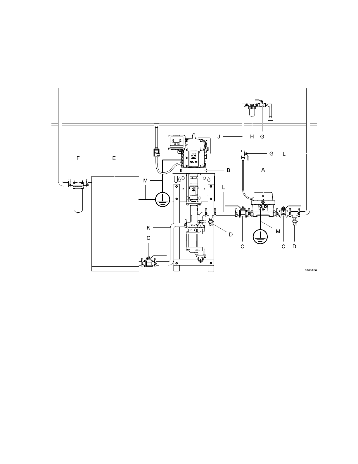
•TheTypicalInstallationisonlyaguideforinstalling
systemcomponentsandaccessories.Itisnot
anactualsystemdesign.ContactyourGraco
distributorforassistanceindesigningasystemto
suityourparticularneeds.
•AlwaysuseGenuineGracoPartsandAccessories,
availablefromyourGracodistributor.Ifyousupply
yourownaccessories,besuretheyareadequately
sizedandpressure-ratedforyoursystem.
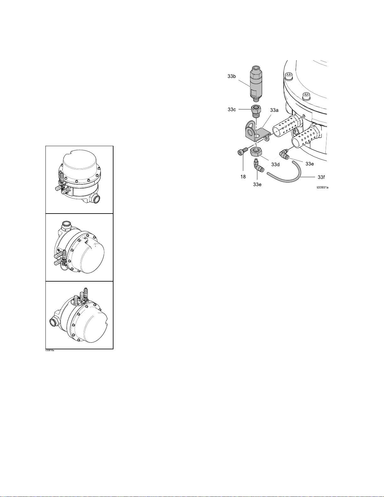
•Referencenumbersandlettersinparentheses
refertothereferencenumbersintheguresandin
thepartslists.
Grounding Grounding
Grounding
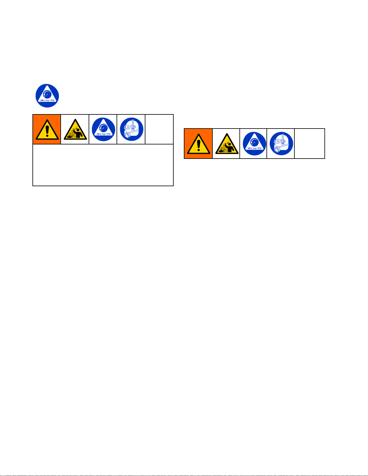
Theequipmentmustbegroundedtoreducethe
riskofstaticsparking.Staticsparkingcancause
fumestoigniteorexplode.Groundingprovidesan
escapewirefortheelectriccurrent.
Groundthesuppressorandtherestofyoursystem.
Groundthesuppressorandallothersprayequipment
usedorlocatedinthesprayarea.Thefollowingare
minimumrequirementsforgroundingabasicspray
system.Yoursystemmayincludeotherequipmentor
objectswhichmustalsobegrounded.Alwayscheck
yourlocalelectricalcodefordetailedgrounding
instructions.Besureyoursystemisconnectedtoa
trueearthground.
•Pump: Pump:
Pump:Useagroundwireandclampasdescribed
inyourseparatepumpinstructionmanual.
•Air Air
Aircompressors compressors
compressorsand and
andhydraulic hydraulic
hydraulicpower power
powersupplies: supplies:
supplies:
Followthemanufacturer’srecommendations.
•Air Air
Airand and
anduid uid
uidlines: lines:
lines:Useonlygroundedhoses
withamaximumof150m(500ft)combined
hoselengthtoensuregroundingcontinuity.See
HoseGroundingContinuity,page6.
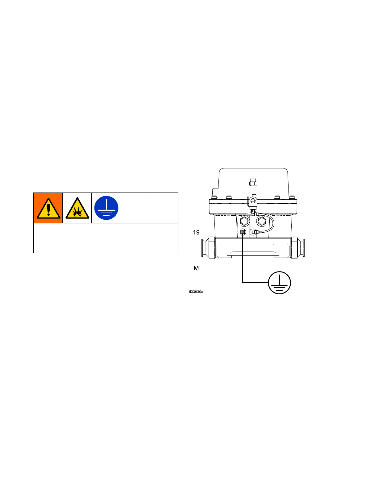
•Surge Surge
Surgesuppressor: suppressor:
suppressor:Useagroundwireandclamp.
Loosenthegroundingscrew(19).Insertoneend
ofa12ga(1.5mm2)minimumgroundwire(M)
behindthegroundingscrewandtightenthescrew
securely.Connecttheclampendoftheground
wiretoatrueearthground.Foragroundwireand
clamp,orderPartNo.222011.
•Spray Spray
Spraygun: gun:
gun:Obtaingroundingthroughaconnection
toaproperlygroundeduidhoseandpump.
•Object Object
Objectbeing being
beingsprayed: sprayed:
sprayed:Followyourlocalcode.
•Fluid Fluid
Fluidsupply supply
supplycontainer: container:
container:Followyourlocalcode.
•All All
Alluid uid
uidpails pails
pailsused used
usedwhen when
whenushing: ushing:
ushing:Followyour
localcode.Useonlyconductivemetalpails
placedonagroundedsurface.Donotplacethe
pailonanonconductivesurface,suchaspaper
orcardboard,whichinterruptsthegrounding
continuity.
•Tomaintaingroundingcontinuitywhenushingor
relievingpressure,alwaysholdametalpartofthe
gunrmlytothesideofagroundedmetalpail,
thentriggerthegun.
Figure1GroundtheSuppressor
Hose Hose
HoseGrounding Grounding
GroundingContinuity Continuity
Continuity
Properhosegroundingcontinuityisessentialto
maintainingagroundedspraysystem.Checkthe
electricalresistanceofyourairanduidhosesat
leastonceaweek.Ifyourhosedoesnothavea
tagonitwhichspeciesthemaximumelectrical
resistance,contactthehosesupplierormanufacturer
forthemaximumresistancelimits.Usearesistance
meterintheappropriaterangeforyourhoseto
checktheresistance.Iftheresistanceexceedsthe
recommendedlimits,replacethehoseimmediately.
Flushing Flushing
FlushingSafety Safety
Safety
Beforeushing,besuretheentiresystem
andushingpailsareproperlygrounded.See
Grounding,page6.
63A6103A

Installation
Typical Typical
TypicalInstallation Installation
Installation
The The
Thesurge surge
surgesuppressor suppressor
suppressoris is
issold sold
soldseparately separately
separatelyfrom from
fromall all
allaccessories. accessories.
accessories.Filters, Filters,
Filters,regulators, regulators,
regulators,ttings, ttings,
ttings,hoses, hoses,
hoses,and and
andso so
soon, on,
on,are are
are
shown shown
shownhere here
hereto to
todepict depict
depictone one
onepossible possible
possiblesystem system
systemsetup. setup.
setup.
This This
Thisinstallation installation
installationis is
isonly only
onlya a
aguide guide
guidefor for
forselecting selecting
selectingand and
andinstalling installing
installinga a
asystem. system.
system.It It
Itis is
isnot not
notan an
anactual actual
actualsystem system
systemdesign. design.
design.Contact Contact
Contact
your your
yourGraco Graco
Gracodistributor distributor
distributorfor for
forassistance assistance
assistancein in
indesigning designing
designinga a
asystem system
systemto to
tosuit suit
suityour your
yourneeds. needs.
needs.
KEY KEY
KEY
A A
ASurge Surge
Surgesuppressor suppressor
suppressorH H
HAir Air
Airlter lter
lter
B B
BPump Pump
PumpJ J
JAir Air
Airline line
lineto to
tosurge surge
surgesuppressor suppressor
suppressor
C C
CFluid Fluid
Fluidshutoff shutoff
shutoffvalve valve
valveK K
KInlet Inlet
Inletuid uid
uidline line
line
D D
DFluid Fluid
Fluiddrain drain
drainvalve* valve*
valve*L L
LOutlet Outlet
Outletuid uid
uidline line
line
E E
EMix Mix
Mixtank tank
tankM M
MGround Ground
Groundwire wire
wire
F F
FFluid Fluid
Fluidlter lter
lter
G G
GBleed Bleed
Bleed- -
-type type
typemaster master
masterair air
airvalve* valve*
valve*
* *
*Required Required
Requiredfor for
forsafe safe
safeoperation. operation.
operation.Must Must
Mustbe be
be
purchased purchased
purchasedseparately. separately.
separately.
3A6103A7

Installation
Mounting Mounting
Mounting
Theactivesurgesuppressorcanbemounted
horizontallyorvertically.Formoreinformation,see
DimensionsandMountingHoleLayout,page16and
Figure2,page9in
Possiblebreathervalvemountingpositions,page9.
Fluid Fluid
FluidInlet Inlet
Inletand and
andOutlet Outlet
OutletPorts Ports
Ports
Eitherportmaybeusedastheuidinlet.The
directionofuidowdoesnotaffecttheperformance.
SeeDimensionsandMountingHoleLayout,page16.
NOTE:Theinletandoutletadapterttingsusea
non-standardthreadtotintotheuidcover(1).You
mustuseGraco-approvedttingstopreventthread
damage.ContactyourGracodistributorforoptional
ttings.
Fluid Fluid
FluidLines Lines
Linesand and
andAccessories Accessories
Accessories
Properlinesizingisanimportantpartofthesystem.
ContactyourGracodistributorifyouneedassistance.
Toobtainproperowthroughthesystem,usethe
propersizeplumbing.
•Useaminimum51mm(2in.)diameterpipeand
plumbing.
•Useaminimum25mm(1in.)diameterexible
hosebetweenthepumpandsuppressoranda
hardorexiblepipeafterthesuppressor.
Auiddrainvalveisrequiredinyoursystemtohelp
reducetheriskofseriousinjury,includingsplashing
uidintheeyesorontheskin,orcontamination
fromhazardousuidswhenrelievingpressure.
Openingtheuiddrainvalvehelpsrelievepressure
inthesurgesuppressor,pumps,hose,andgun
aftershuttingoffthesystem.Triggeringthegunto
relievepressuremaynotbesufcient.
1.Installauiddrainvalve(D)nearthesurge
suppressoroutlet.
2.Installauidshutoffvalve(C)beforeandafter
thesurgesuppressortoisolateitwhenservicing
thesuppressor.
83A6103A

Installation
Breather Breather
BreatherValve Valve
ValveMounting Mounting
Mounting
Requirements Requirements
Requirements
Thebreathervalvemustbemountedinavertical
positiontofunctionproperly.Thebreathervalve
mountingbracketallowstherepositioningofthe
valvefortherequiredverticalmounting.
Thebreathervalvesystemindicatesabreachin
thediaphragm.Ifabreachoccurs,theworkinguid
passesthroughthediaphragmtothebacksideofthe
diaphragm.Fluidthenowsintothecleartubingand
intothebreathervalve.Thebreathervalvestopsthe
uidfromexitingthesuppressor.
Figure2Possiblebreathervalvemountingpositions
Breather Breather
BreatherValves Valves
Valves
1.Boththebreathervalve(33b)andthevalve
tting(33c)arepreassembled.Onthemufer
side,assemblethebreathervalve(33b)tothe
mountingbracket(33a)withthejamnut(33d).
Torqueto8–10ft-lb(11–14N•m).Threadtheair
tting(33e)intothevalvetting(33c).
NOTE:Beforeassemblingthebreathervalve
system,verifyclearancesaroundthemuferand
airinletbysettingupthebreathervalvesvertically
asatest.Mountingbracketshaveseveral
possiblebreathervalvemountingcongurations.
2.Attachtheassemblytotheaircover(13)using
ascrew(18).
NOTE:Breathervalveassembliesmustbe
mountedandinstalledwiththebreathervalvein
theverticaldirectionforproperoperation.See
theillustrationsinFigure2,page9forsome
possiblemountingcongurations.
3.Connectthetubing(33f)tothettings(33e)to
completethebreathervalveassembly.
3A6103A9

Operation
Operation Operation
Operation
Pressure Pressure
PressureRelief Relief
ReliefProcedure Procedure
Procedure
FollowthePressureReliefProcedure
wheneveryouseethissymbol.
Thisequipmentstayspressurizeduntilpressure
ismanuallyrelieved.Tohelppreventserious
injuryfrompressurizeduid,suchassplashing
intheeyesoronskin,followthePressure Pressure
PressureRelief Relief
Relief
Procedure Procedure
Procedurewhenyoustoppumpingandbeforeyou
clean,check,orservicetheequipment.
1.Shutoffthepowertothepump.
•Inahydraulicsystem,closethehydraulic
shutoffvalves.
•Inanair-poweredsystem,closethepumpair
regulator,andclosethebleed-typemasterair
valve(requiredinyoursystem).
2.Closetheuidshutoffvalvesfromthesupply
tanks.
3.Holdametalpartofthegun(ifused)toa
groundedmetalpail.Triggertheguntorelieve
thepressure.
4.Opentheuiddrainvalve(requiredinyour
system),havingacontainerreadytocatchthe
drainage.Keephandsawayfromtheendofthe
drainvalvewhenopeningit.
5.Leavethedrainvalveopenuntilyouareready
toreturntooperation.
6.Closethebleedtypeairvalvethatisconnected
totheinletofthesurgesuppressor.
7.Torelievetheairpressureinthesurge
suppressor,ensurethatyouhaverelieved
theuidpressure.Thesurgesuppressorwill
automaticallyrelieveandexhaustairfromits
chamber
Charge Charge
Chargethe the
theSuppressor Suppressor
Suppressor
1.FollowthePressureReliefProcedure,page10.
2.Alwaysre-torqueallofthecapscrewsusing
astar-patternsequencebeforeyouoperate
thesurgesuppressortoensureagainstuid
orgasleakage.Fortorquespecications,see
Parts,page14.
3.Opentheairvalvetothesuppressor.Whenthe
uidpressureishighenough,thepoppetvalves
trigger,injectingairintothesuppressoruntilitis
balanced.
NOTE:Themaximumuidworkingpressurefor
thesurgesuppressoris350psi(2.4MPa,24
bar).Donotexceedtheuidlinepressureorthe
associatedsuppressorairpressure.
Relieve Relieve
RelieveAir Air
AirPressure Pressure
Pressurein in
inthe the
the
Suppressor Suppressor
Suppressor
1.Closetheairvalve.
2.Relieveuidpressurefromthesystem.Follow
thePressureReliefProcedure,page10.The
suppressorventstheairpressure.
103A6103A

Troubleshooting
Troubleshooting Troubleshooting
Troubleshooting
•FollowthePressureReliefProcedure,page
10beforeyoucheckorservicethesurge
suppressororremovethesurgesuppressorfrom
thesystem.
•Checkallpossibleproblemsandcausesbefore
disassembly.
•Ifyoureplacethediaphragm,donotattemptto
makeanewoneyourself.UseonlygenuineGraco
parts.Othermaterialsmaynotstanduptothe
pressuresdevelopedinthesuppressorortothe
uidbeingpumped.Aruptureddiaphragmwill
disablethesurgesuppressor.
Problem Problem
ProblemCause Cause
CauseSolution Solution
Solution
Thesurgesuppressorisundersized
fortheapplication.
Reducetheworkinguidpressure
and/orowrate.
Installalargersurgesuppressor
model.
Installasurgeregulator(SR200)
Poorpulsationreduction.
Extendedpumpchange-overtime
duetowornorheldopencheck
valves.
Repairthepistonpump.
3A6103A11

Repair/Service
Repair/Service Repair/Service
Repair/Service
Install Install
Installthe the
theDiaphragm Diaphragm
DiaphragmRepair Repair
RepairKit Kit
Kit
TheDiaphragmRepairKit(17X733)isavailable
andcanbeorderedseparately.SeethePartsList
footnoteinParts,page14.
FollowthePressureReliefProcedure,page10be-
foreyoucheckorservicethesurgesuppressoror
removethesurgesuppressorfromthesystem.All
uidandairpressuremustberelievedcompletely
beforeyouattemptanyservice.
Disassemble Disassemble
Disassemblethe the
theSurge Surge
SurgeSuppressor Suppressor
Suppressor
1.FollowthePressureReliefProcedure,page10to
relieveuidandairpressure.
2.Disassembletheairhousing.
a.Removethecapscrews(14)andlock
washers(23)
b.Separatetheaircover(13)fromthepiston
housing(6).Becarefulthatyoudonot
damagethemachinedangesurfacesor
componentsattachedtoeitherhousing.
c.Usea10mmsocketdrivertoloosenthe
pistonassembly(P).Unscrewandremove
thepistonassembly(P)fromthepiston
housing(6)
3.Disassemblethepistonassembly(P).
a.Clamptheshaft(8)ontheatsinavise.
b.Unscrewtheretainingscrew(12).
c.Separatetheshaft(8),screw(12),andpiston
(9).
d.Inspecttheo-ring(11).Replaceifnecessary.
4.Reassemblethepistonassembly(P).
a.Installtheo-ring(11)intothepiston(9),and
applygrease.
b.Presstheretainingscrew(12)intothepiston
(9)byhand.
c.Handthreadtheshaft(8)ontothescrew(12).
d.Clamptheshaft(8)ontheatsinavise,and
torquethescrew(12)to75-85ft-lb.
5.Disassembletheuidhousing.
a.Removethecapscrews(22).
b.Separatetheuidcover(1)fromthepiston
housing(6).
c.Removethediaphragm(2),diaphragmplate
(17),andwasher(3).
d.InspecttheL-cupseal(5),bearings(4),and
o-rings(16,10).Replaceifnecessary.
123A6103A

Repair/Service
Reassemble Reassemble
Reassemblethe the
theSurge Surge
SurgeSuppressor Suppressor
Suppressor
1.Reassembletheuidhousing.
a.Turnthehousing(6)upside-down.
b.ApplygreasetotheL-cupseal(5)andinsert
intothebottomofthehousing(6)withthe
seal’so-ring(5a)facingoutfromtheuid
side.
c.Pressoneofthebearings(4)intothebottom
ofthehousing(6)toretaintheL-cupseal(5)
intheuidsideofthehousing(6).
d.Turnthehousing(6)right-sideup.
e.Installtheotherbearing(4)fromtheairside
ofthehousing(6)sothattheL-cupseal(5)
issandwichedbetweenthetwobearings(4).
2.Installtheo-ring(10)onthepistonassembly(P),
andapplygrease.
3.Applygreasetotheinnerdiameterofthehousing
(6)andinsertthepistonassembly(P)withthe
shaft(8)passingthroughtheshaftbearings(4).
4.Applybluethreadlockertothethreadsofthe
shaft(8).
5.Insertthebackerplate(17)andwasher(3)over
thethreadsofthediaphragm(2).
6.Threadthediaphragmassemblyontotheshaft
(8)totightentohand-tight.
7.Aligntheuidhousing(6)andcover(1)withthe
poppetport.Installandtightenthebolts(22)in
astarpattern.
8.Usea10mmsocketdrivertotorquetheretainer
screw(12)to50-55ft-lb.
9.Installtheo-ring(16)intothehousing(6).
10.Aligntheaircover(13)andhousing(6).Install
washers(23)andscrews(14)inastarpattern,
andtorqueto15-20ft-lbs.
11.Applygreasetothepoppetvalves(15)before
installing.Torquethepoppetvalves(15)to
100-120in-lb.
12.Installthepipeplug(26)andexhaustmufers
(7)withthreadsealant.
13.Replacethebreathervalve(33b)andttings
(33cand33e),ifneeded.
3A6103A13

Parts
Ref Ref
RefPart Part
PartDescription Description
DescriptionQty Qty
Qty
117T216COVER,uid
machiningsurge
suppressor
1
2* *
*16W384DIAPHRAGM,
overmolded,350cc
1
317B546WASHER1
4* *
*—BEARING,shaft2
5* *
*25D846PACKING,L-cup1
617W897HOUSING,machined
bodysurgesuppressor
1
715M940MUFFLER,airvalve,
medium
2
8—SHAFT,pump,350cc1
9—PISTON,helper1
1016X315PACKING,o-ring1
11107204PACKING,o-ring1
12—SCREW,retaining
piston
1
1317W896COVER,airmachining
surgesuppressor
1
14109114SCREW,cap10
15—VALVE,pilot2
16—O-RING1
Ref Ref
RefPart Part
PartDescription Description
DescriptionQty Qty
Qty
1716X307PLATE,backer,350cc1
19116343SCREW,ground1
22* *
*—SCREW,M10x30x
1.5
12
23104572WASHER,lockspring10
24188286FITTING2
25107078PACKING,o-ring2
26100139PLUG,pipe1
30s188621LABEL,warning1
33al—BRACKET,mounting
valve
1
33bl—VALVE,breather1
33cl—FITTING,adaptervalve2
33dl—NUT1
33el—FITTING,maleswivel,
air
2
33fl* *
*—TUBE,5/32ODnylon,
pre-cutto4.5in.
1
s
ReplacementDangerandWarninglabels,tags,
andcardsareavailableatnocost.
l
IncludedinBreatherValveKit17X529.
* *
*
IncludedinDiaphragmRepairKit17X733.
3A6103A15

TechnicalSpecications
Technical Technical
TechnicalSpecications Specications
Specications
US US
USMetric Metric
Metric
Maximumuidworkingpressure350psi24bar,2.4MPa
Maximumairchargepressure100psi7bar,0.7MPa
Maximumowrate*20GPM75.7LPM
Maximumoperatingtemperature120°F50°C
Wettedparts304stainlesssteel,PTFE
*Maximumowratesarerecommendedmaximumsforpeakperformance.Exceedingthesevaluesreduces
thesurgesuppressor’sabilitytodampenpulsation.
3A6103A17

Graco Graco
GracoStandard Standard
StandardWarranty Warranty
Warranty
GracowarrantsallequipmentreferencedinthisdocumentwhichismanufacturedbyGracoandbearingitsnametobe
freefromdefectsinmaterialandworkmanshiponthedateofsaletotheoriginalpurchaserforuse.Withtheexception
ofanyspecial,extended,orlimitedwarrantypublishedbyGraco,Gracowill,foraperiodoftwelvemonthsfromthe
dateofsale,repairorreplaceanypartoftheequipmentdeterminedbyGracotobedefective.Thiswarrantyapplies
onlywhentheequipmentisinstalled,operatedandmaintainedinaccordancewithGraco’swrittenrecommendations.
Thiswarrantydoesnotcover,andGracoshallnotbeliableforgeneralwearandtear,oranymalfunction,damage
orwearcausedbyfaultyinstallation,misapplication,abrasion,corrosion,inadequateorimpropermaintenance,
negligence,accident,tampering,orsubstitutionofnon-Gracocomponentparts.NorshallGracobeliablefor
malfunction,damageorwearcausedbytheincompatibilityofGracoequipmentwithstructures,accessories,
equipmentormaterialsnotsuppliedbyGraco,ortheimproperdesign,manufacture,installation,operationor
maintenanceofstructures,accessories,equipmentormaterialsnotsuppliedbyGraco.
Thiswarrantyisconditionedupontheprepaidreturnoftheequipmentclaimedtobedefectivetoanauthorized
Gracodistributorforvericationoftheclaimeddefect.Iftheclaimeddefectisveried,Gracowillrepairorreplace
freeofchargeanydefectiveparts.Theequipmentwillbereturnedtotheoriginalpurchasertransportationprepaid.
Ifinspectionoftheequipmentdoesnotdiscloseanydefectinmaterialorworkmanship,repairswillbemadeata
reasonablecharge,whichchargesmayincludethecostsofparts,labor,andtransportation.
THIS THIS
THISWARRANTY WARRANTY
WARRANTYIS IS
ISEXCLUSIVE, EXCLUSIVE,
EXCLUSIVE,AND AND
ANDIS IS
ISIN IN
INLIEU LIEU
LIEUOF OF
OFANY ANY
ANYOTHER OTHER
OTHERWARRANTIES, WARRANTIES,
WARRANTIES,EXPRESS EXPRESS
EXPRESSOR OR
ORIMPLIED, IMPLIED,
IMPLIED,
INCLUDING INCLUDING
INCLUDINGBUT BUT
BUTNOT NOT
NOTLIMITED LIMITED
LIMITEDTO TO
TOWARRANTY WARRANTY
WARRANTYOF OF
OFMERCHANTABILITY MERCHANTABILITY
MERCHANTABILITYOR OR
ORWARRANTY WARRANTY
WARRANTYOF OF
OFFITNESS FITNESS
FITNESSFOR FOR
FORA A
A
PARTICULAR PARTICULAR
PARTICULARPURPOSE. PURPOSE.
PURPOSE.
Graco’ssoleobligationandbuyer’ssoleremedyforanybreachofwarrantyshallbeassetforthabove.Thebuyer
agreesthatnootherremedy(including,butnotlimitedto,incidentalorconsequentialdamagesforlostprots,lost
sales,injurytopersonorproperty,oranyotherincidentalorconsequentialloss)shallbeavailable.Anyactionfor
breachofwarrantymustbebroughtwithintwo(2)yearsofthedateofsale.
GRACO GRACO
GRACOMAKES MAKES
MAKESNO NO
NOWARRANTY, WARRANTY,
WARRANTY,AND AND
ANDDISCLAIMS DISCLAIMS
DISCLAIMSALL ALL
ALLIMPLIED IMPLIED
IMPLIEDWARRANTIES WARRANTIES
WARRANTIESOF OF
OFMERCHANTABILITY MERCHANTABILITY
MERCHANTABILITYAND AND
AND
FITNESS FITNESS
FITNESSFOR FOR
FORA A
APARTICULAR PARTICULAR
PARTICULARPURPOSE, PURPOSE,
PURPOSE,IN IN
INCONNECTION CONNECTION
CONNECTIONWITH WITH
WITHACCESSORIES, ACCESSORIES,
ACCESSORIES,EQUIPMENT, EQUIPMENT,
EQUIPMENT,MATERIALS MATERIALS
MATERIALS
OR OR
ORCOMPONENTS COMPONENTS
COMPONENTSSOLD SOLD
SOLDBUT BUT
BUTNOT NOT
NOTMANUFACTURED MANUFACTURED
MANUFACTUREDBY BY
BYGRACO. GRACO.
GRACO.Theseitemssold,butnotmanufacturedby
Graco(suchaselectricmotors,switches,hose,etc.),aresubjecttothewarranty,ifany,oftheirmanufacturer.Graco
willprovidepurchaserwithreasonableassistanceinmakinganyclaimforbreachofthesewarranties.
InnoeventwillGracobeliableforindirect,incidental,specialorconsequentialdamagesresultingfromGraco
supplyingequipmenthereunder,orthefurnishing,performance,oruseofanyproductsorothergoodssoldhereto,
whetherduetoabreachofcontract,breachofwarranty,thenegligenceofGraco,orotherwise.
FORGRACOCANADACUSTOMERS
ThePartiesacknowledgethattheyhaverequiredthatthepresentdocument,aswellasalldocuments,noticesand
legalproceedingsenteredinto,givenorinstitutedpursuantheretoorrelatingdirectlyorindirectlyhereto,bedrawn
upinEnglish.LespartiesreconnaissentavoirconvenuquelarédactionduprésentedocumentseraenAnglais,
ainsiquetousdocuments,avisetprocéduresjudiciairesexécutés,donnésouintentés,àlasuitedeouenrapport,
directementouindirectement,aveclesprocéduresconcernées.
Graco Graco
GracoInformation Information
Information
ForthelatestinformationaboutGracoproducts,visitwww.graco.com.
Forpatentinformation,seewww.graco.com/patents.
To To
Toplace place
placean an
anorder, order,
order,contactyourGracoDistributororcalltoidentifythenearestdistributor.
Phone: Phone:
Phone:612-623-6921or or
orToll Toll
TollFree: Free:
Free:1-800-328-0211Fax: Fax:
Fax:612-378-3505
Allwrittenandvisualdatacontainedinthisdocumentreectsthelatestproductinformationavailableatthetimeofpublication.
Gracoreservestherighttomakechangesatanytimewithoutnotice.
OriginalInstructions.ThismanualcontainsEnglish.MM3A6103
Graco Graco
GracoHeadquarters: Headquarters:
Headquarters:Minneapolis
International International
InternationalOfces: Ofces:
Ofces:Belgium,China,Japan,Korea
GRACO GRACO
GRACOINC. INC.
INC.AND AND
ANDSUBSIDIARIES SUBSIDIARIES
SUBSIDIARIES• •
•P.O. P.O.
P.O.BOX BOX
BOX1441 1441
1441• •
•MINNEAPOLIS MINNEAPOLIS
MINNEAPOLISMN MN
MN55440-1441 55440-1441
55440-1441• •
•USA USA
USA
Copyright Copyright
Copyright2018, 2018,
2018,Graco Graco
GracoInc. Inc.
Inc.All All
AllGraco Graco
Gracomanufacturing manufacturing
manufacturinglocations locations
locationsare are
areregistered registered
registeredto to
toISO ISO
ISO9001. 9001.
9001.
www.graco.com
RevisionA,May2018
Table of contents
Other Graco Surge Protector manuals