manuals.online logo
Brands
  1. Home
  2. •
  3. Brands
  4. •
  5. Graco
  6. •
  7. Water Pump
  8. •
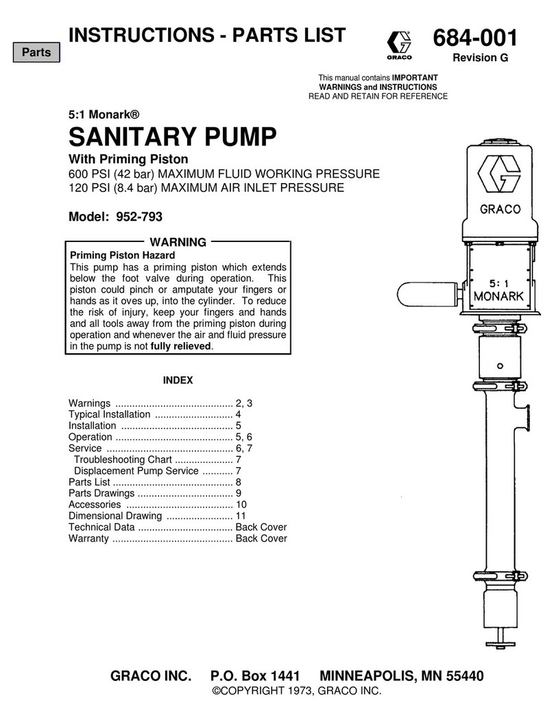
  9. Graco 207321 Operation manual

Graco 207321 Operation manual

This manual suits for next models

2

Other Graco Water Pump manuals

Graco President E Series Operation manual

Graco

Graco President E Series Operation manual

Graco Check-Mate 450 User manual

Graco

Graco Check-Mate 450 User manual

Graco 222078 Operation manual

Graco

Graco 222078 Operation manual

Graco C Series User manual

Graco

Graco C Series User manual

Graco Husky 1050A Instruction Manual

Graco

Graco Husky 1050A Instruction Manual

Graco 232-504 Operation manual

Graco

Graco 232-504 Operation manual

Graco 190ES 261825 Assembly instructions

Graco

Graco 190ES 261825 Assembly instructions

Graco RoadLazer A Series Operation manual

Graco

Graco RoadLazer A Series Operation manual

Graco 258771 Use and care manual

Graco

Graco 258771 Use and care manual

Graco Series A Setup guide

Graco

Graco Series A Setup guide

Graco Series A Use and care manual

Graco

Graco Series A Use and care manual

Graco Series B Operation manual

Graco

Graco Series B Operation manual

Graco II 2 GD Operation manual

Graco

Graco II 2 GD Operation manual

Graco Aluminum Husky 2150 LP User manual

Graco

Graco Aluminum Husky 2150 LP User manual

Graco 244197 Operation manual

Graco

Graco 244197 Operation manual

Graco Fast-Flo Datasheet

Graco

Graco Fast-Flo Datasheet

Graco Husky 515 D51 Series User manual

Graco

Graco Husky 515 D51 Series User manual

Graco G3 Series User manual

Graco

Graco G3 Series User manual

Graco Power-Flo Series User manual

Graco

Graco Power-Flo Series User manual

Graco saniforce 2150 Instruction Manual

Graco

Graco saniforce 2150 Instruction Manual

Graco 17P750 User manual

Graco

Graco 17P750 User manual

Graco 203872 Operation manual

Graco

Graco 203872 Operation manual
Graco 248061 User manual

Graco

Graco 248061 User manual

Graco GBL 7500 User manual

Graco

Graco GBL 7500 User manual

Popular Water Pump manuals by other brands

Watershed Innovations HYDRAPUMP SMART FLEX Instructional manual

Watershed Innovations

Watershed Innovations HYDRAPUMP SMART FLEX Instructional manual

Messner MultiSystem MPF 3000 operating instructions

Messner

Messner MultiSystem MPF 3000 operating instructions

Xylem Bell & Gossett WEHT0311M Installation, operation and maintenance instructions

Xylem

Xylem Bell & Gossett WEHT0311M Installation, operation and maintenance instructions

WilTec 50739 Operation manual

WilTec

WilTec 50739 Operation manual

Franklin Electric Little Giant 555702 HRK-360S instruction sheet

Franklin Electric

Franklin Electric Little Giant 555702 HRK-360S instruction sheet

Ingersoll-Rand PD02P Series Operator's manual

Ingersoll-Rand

Ingersoll-Rand PD02P Series Operator's manual

VS ZJ Series Operating	 instruction

VS

VS ZJ Series Operating instruction

Flotec FPZS50RP owner's manual

Flotec

Flotec FPZS50RP owner's manual

SKF Lincoln FlowMaster II User and maintenance instructions

SKF

SKF Lincoln FlowMaster II User and maintenance instructions

Xylem Lowara LSB Series Installation, operation and maintenance instructions

Xylem

Xylem Lowara LSB Series Installation, operation and maintenance instructions

Water Duro Pumps DCJ500 Operating & installation instructions

Water

Water Duro Pumps DCJ500 Operating & installation instructions

Action P490 Operating instructions & parts manual

Action

Action P490 Operating instructions & parts manual

Flo King Permacore Reusable Carbon Bag Disassembly. & Cleaning Instructions

Flo King

Flo King Permacore Reusable Carbon Bag Disassembly. & Cleaning Instructions

ARO ARO PD15P-X Operator's manual

ARO

ARO ARO PD15P-X Operator's manual

Pumptec 112V Series Operating instructions and parts manual

Pumptec

Pumptec 112V Series Operating instructions and parts manual

Virax 262070 user manual

Virax

Virax 262070 user manual

Neptun NPHW 5500 operating instructions

Neptun

Neptun NPHW 5500 operating instructions

Sensidyne Gilian BDX-II Operation & service manual

Sensidyne

Sensidyne Gilian BDX-II Operation & service manual

manuals.online logo
manuals.online logoBrands
  • About & Mission
  • Contact us
  • Privacy Policy
  • Terms and Conditions

Copyright 2025 Manuals.Online. All Rights Reserved.

Instructions – Parts List
GRACO INC.ąP.O. BOX 1441ąMINNEAPOLIS, MNą55440-1441
Copyright 2002, Graco Inc. is registered to I.S. EN ISO 9001
STAINLESS STEEL
5:1 Ratio BulldogrPumps
500 psi (3.5 MPa, 35 bar) Maximum Working Pressure
55 Gallon (200 liter) Size
Part No. 207321, Series G
Rubber Packed
Stubby Size
Part No. 206418, Series D
Rubber Packed
Part No. 206796, Series D
PTFErPacked
306818J
Read warnings and instructions.
See page 2 for Table of Contents.
Stubby Size
06823
55 Gallon (200 liter) Size
06824
Parts
2306818
Table of Contents
Warnings 2. . . . . . . . . . . . . . . . . . . . . . . . . . . . . . . . . . . . . .
Installation 4. . . . . . . . . . . . . . . . . . . . . . . . . . . . . . . . . . . . .
Operation 6. . . . . . . . . . . . . . . . . . . . . . . . . . . . . . . . . . . . .
Maintenance 7. . . . . . . . . . . . . . . . . . . . . . . . . . . . . . . . . . .
Troubleshooting 9. . . . . . . . . . . . . . . . . . . . . . . . . . . . . . . .
Service 10. . . . . . . . . . . . . . . . . . . . . . . . . . . . . . . . . . . . . .
Parts 14. . . . . . . . . . . . . . . . . . . . . . . . . . . . . . . . . . . . . . . .
Technical Data 18. . . . . . . . . . . . . . . . . . . . . . . . . . . . . . . .
Mounting Hole Layout 18. . . . . . . . . . . . . . . . . . . . . . . . . .
Dimensions 19. . . . . . . . . . . . . . . . . . . . . . . . . . . . . . . . . . .
Graco Standard Warranty 20. . . . . . . . . . . . . . . . . . . . . .
Graco Information 20. . . . . . . . . . . . . . . . . . . . . . . . . . . . .
Symbols
Warning Symbol
WARNING
This symbol alerts you to the possibility of serious
injury or death if you do not follow the instructions.
Caution Symbol
CAUTION
This symbol alerts you to the possibility of damage to
or destruction of equipment if you do not follow the
corresponding instructions.
WARNING
INSTRUCTIONS
EQUIPMENT MISUSE HAZARD
Equipment misuse can cause the equipment to rupture, malfunction, or start unexpectedly and result
in a serious injury.
DThis equipment is for professional use only.
DRead all the instruction manuals, tags, and labels before operating the equipment.
DUse the equipment only for its intended purpose. If you are uncertain about usage, call your Graco
distributor.
DDo not alter or modify this equipment. Use only genuine Graco parts and accessories.
DCheck the equipment daily. Repair or replace worn or damaged parts immediately.
DDo not exceed the maximum working pressure of the lowest rated system component.
DUse fluids that are compatible with the equipment wetted parts. See the Technical Data section of
all the equipment manuals. Read the fluid manufacturer’s warnings.
DRoute the hoses away from traffic areas, sharp edges, moving parts, and hot surfaces. Do not
expose Graco hoses to temperatures above 180_F (82_C) or below –40_F (–40_C).
DDo not use hoses to pull equipment.
DDo not lift pressurized equipment.
DWear hearing protection when operating this equipment.
DComply with all applicable local, state, and national fire, electrical, and other safety regulations.
TOXIC FLUID HAZARD
Hazardous fluids or toxic fumes can cause a serious injury or death if splashed in the eyes or on the
skin, swallowed, or inhaled.
DKnow the specific hazards of the fluid you are using. Read the fluid manufacturer’s warnings.
DStore hazardous fluid in an approved container. Dispose of the hazardous fluid according to all
local, state, and national guidelines.
DWear appropriate protective clothing, gloves, eyewear, and respirator.
3306818
WARNING
FIRE AND EXPLOSION HAZARD
Improper grounding, poor air ventilation, open flames, or sparks can cause a hazardous condition and
result in fire or explosion and serious injury.
DGround the equipment and the object being sprayed. See Ground the System on page 4.
DProvide fresh air ventilation to avoid the buildup of flammable fumes from solvent or the fluid being
sprayed.
DExtinguish all the open flames or pilot lights in the spray area.
DElectrically disconnect all the equipment in the spray area.
DKeep the spray area free of debris, including solvent, rags, and gasoline.
DDo not turn on or off any light switch in the spray area while operating or if fumes are present.
DDo not smoke in the spray area.
DDo not operate a gasoline engine in the spray area.
DIf there is any static sparking while using the equipment, stop spraying immediately. Identify and
correct the problem.
PRESSURIZED EQUIPMENT HAZARD
Spray from the gun, hose leaks, or ruptured components can splash fluid in the eyes or on the skin
and cause serious injury.
DDo not stop or deflect fluid leaks with your hand, body, glove, or rag.
DFollow the Pressure Relief Procedure on page 6 whenever you: are instructed to relieve the
pressure; stop spraying; clean, check, or service the equipment; and install or clean the fluid
nozzle.
DTighten all the fluid connections before operating the equipment.
DCheck the hoses, tubes, and couplings daily. Replace worn, damaged, or loose parts immediately.
Permanently coupled hoses cannot be repaired; replace the entire hose.
MOVING PARTS HAZARD
Moving parts, such as the air motor piston, can pinch or amputate fingers.
DDo not operate the equipment with the air motor shield removed.
DKeep clear of any moving parts when starting or operating the equipment.
4306818
Installation
Ground the System
In low pressure air spray systems, static sparking is
generally not a problem; however, some simple pre-
cautions should be taken to reduce the risk. Check
your local code for detailed grounding instructions for
your area and type of equipment, and ground all of this
equipment.
DPump: loosen the grounding lug locknut (W) and
washer (X). Insert one end of a 12 ga. (1.5 mm2)
minimum ground wire (Y) into the slot in the lug (Z)
and tighten the locknut securely. See Fig. 1 .
Connect the other end of the wire to a true earth
ground. Order Part No. 237569 Grounding Wire
and Clamp.
DAir compressor: according to manufacturer’s rec-
ommendations.
DObject being sprayed: according to local code.
DFluid supply container: according to local code.
DAll solvent pails used when flushing, according to
local codes. Use only metal pails, which are con-
ductive. Do not place the pail on a non-conductive
surface, such as paper or cardboard, which inter-
rupts the grounding continuity.
DTo maintain grounding continuity when flushing or
relieving pressure, always hold a metal part of the
gun firmly to the side of a grounded metal pail, then
trigger the gun.
Fig. 1
06825
Y
Z
W
X
5306818
Installation
KEY
A
B
C
D
E
F
G
H
J
K
Pump
Air Line Filter
Bleed-Type Master Air Valve
Fluid Drain Valve
Fluid Supply Hose
Hydra-Clean Spray Gun
Fluid Suction Hose
Wall Bracket
Ground Wire
Air Regulator
Typical Installation
7442A
G
H
A
J
DE
B
F
C
K
NOTE: Reference numbers and letters in parentheses
in the text refer to the callouts in the Figures and Parts
Drawing.
The typical installation shown above is only a guide to
selecting and installing required and optional accesso-
ries. For assistance in designing a system to suit your
needs, contact your Graco distributor.
Mount the pump to suit the type of installation planned.
The pump mounting hole layout and dimensions are
shown on pages 18 and 19.
WARNING
A bleed-type master air valve (C) and a fluid drain
valve (D) are required in your system. These
accessories help reduce the risk of serious injury,
including fluid injection and splashing of fluid in the
eyes or on the skin, and injury from moving parts if
you are adjusting or repairing the pump.
The bleed-type master air valve relieves air trapped
between this valve and the pump after the air is
shut off. Trapped air can cause the pump to cycle
unexpectedly. Locate the valve close to the pump.
The fluid drain valve assists in relieving fluid pres-
sure in the displacement pump, hose, and gun.
Triggering the gun to relieve pressure may not be
sufficient.
Connect a fluid suction hose (G) to the 2 in. npt(f)
intake of the pump if it is not immersed.
Next, install a bleed-type master air valve (C) to relieve
air trapped between the valve and the pump, an air
regulator (K) to control pump speed, an air filter (B) to
remove harmful dirt and moisture from the compressed
air supply, and another bleed-type air valve to isolate
the accessories for servicing.
On the fluid supply line, install a fluid drain valve (D) to
assist in relieving pressure.
Be sure all air and fluid accessories are properly sized
for your system, and are compatible with the fluid you
are pumping.
6306818
Operation
Pressure Relief Procedure
PRESSURIZED EQUIPMENT HAZARD
The system pressure must be manually relieved to
prevent the system from starting or spraying acci-
dentally. To reduce the risk of an injury from acci-
dental spray from the gun, splashing fluid, or mov-
ing parts, follow the Pressure Relief Procedure
whenever you:
Dare instructed to relieve the pressure,
Dstop spraying,
Dcheck or service any of the system equipment,
Dor install or clean the spray nozzle.
WARNING
1. Close the pump air regulator.
2. Close the bleed-type master air valve (required in
your system).
3. Hold a metal part of the gun firmly to a grounded
metal waste container and trigger the gun to
relieve fluid pressure.
4. Open the pump drain valve (required in your
system), having a container ready to catch the
drainage.
If you suspect that the spray tip or hose is completely
clogged, or that pressure has not been fully relieved
after following the steps above, very slowly loosen the
tip guard retaining nut or hose end coupling and relieve
pressure gradually, then loosen completely. Now clear
the tip or hose.
Using the Pump
WARNING
To reduce the risk of serious injury whenever you
are instructed to relieve pressure, always follow the
Pressure Relief Procedure at left.
WARNING
To reduce the risk of serious injury, including fluid
injection and splashing in the eyes or on the skin,
and property damage, never exceed the maximum
air and fluid working pressure of the lowest rated
component in your system.
The pump was tested in oil, and some oil was left in
the pump. If the oil will contaminate the fluid you are
pumping, flush it out.
Fill the packing nut/wet cup 1/2 full with Graco Throat
Seal Liquid or a compatible solvent. Keep the cup filled
at all times to help prevent the fluid you are pumping
from drying on the displacement rod and damaging the
throat packings.
To start the pump, turn on the main air supply. Open
the bleed-type master air valve (A). Trigger the spray
gun into a grounded metal pail, holding the gun firmly
to the pail. Slowly open the air regulator until the pump
is running smoothly (about 40 psi [280 kPa, 2.8 bar]).
Operate the pump until all air is purged from the sys-
tem. Release the gun trigger and lock the trigger
safety.
Use the air regulator (F) to control fluid pressure and
pump speed. Always use the lowest possible pressure
and cycle rate to achieve the desired results. Higher
pressures cause premature pump wear and gun wear,
and usually do not improve the spray pattern.
In a direct supply system, with adequate air pressure
supplied to the motor, the pump starts when the gun or
dispensing valve is opened, and stalls against pres-
sure when it is closed. In a circulating system, the
pump will run continuously and speed up or slow down
as the system demands.
If the pump accelerates quickly or is running too fast,
stop it immediately. Check the fluid supply and refill it if
necessary. Prime the pump to remove all air from the
system, or flush the pump, relieve the pressure, but
leave the system filled with a compatible solvent.
NOTE: A pump runaway valve (D) installed on the air
line automatically shuts off the pump if it starts to run
too fast.
7306818
Maintenance
Shutdown and Care of the Pump
Always stop the pump at the bottom of its stroke to
prevent fluid from drying on the rod and damaging the
throat packings.
WARNING
To reduce the risk of serious injury whenever you
are instructed to relieve pressure, always follow the
Pressure Relief Procedure on page 6.
Check the tightness of the packing retainer screws (7)
weekly. The screws should be tight enough to stop
leakage, but no tighter. Always relieve the pressure
before adjusting the packing retainer screws. See Fig.
2.
Fig. 2
06827
4
7
21
Flushing
If you are pumping fluid which dries, hardens, or sets
up, flush the system with a compatible solvent as often
as necessary to prevent build up of dried fluid in the
pump or hoses.
WARNING
To reduce the risk of serious injury whenever you
are instructed to relieve pressure, always follow the
Pressure Relief Procedure on page 6.
To reduce the risk of static sparking or splashing in the
eyes or on the skin, relieve the pressure and remove
the spray tip before flushing. Start the pump. Hold a
metal part of the gun/valve firmly to the side of a
grounded metal pail and use the lowest possible fluid
pressure during flushing. When flushing is complete,
relieve the pressure again.
Lubrication
WARNING
To reduce the risk of serious injury whenever you
are instructed to relieve pressure, always follow the
Pressure Relief Procedure on page 6.
The accessory air line lubricator (G) provides automat-
ic air motor lubrication. For daily, manual lubrication,
relieve the pressure, disconnect the regulator, place
about 15 drops of light machine oil in the pump air
inlet, reconnect the regulator and turn on the air supply
to blow oil into the motor.
8306818
Notes
9306818
Troubleshooting
WARNING
To reduce the risk of serious injury whenever you
are instructed to relieve pressure, always follow the
Pressure Relief Procedure on page 6.
Before servicing this equipment always make sure to
relieve the pressure.
Note: Check all possible causes and solutions before
disassembling the pump.
WARNING
Never operate the pump with the air motor shield
removed. Moving parts can pinch or amputate your
fingers or other body parts. When the pump is
operating, the air motor piston (located behind the
air motor shield) moves.
Problem Cause Solution
Pump does not operate, or no fluid Loose or broken pump parts. Disassemble, check, repair.
,
flow. Restricted line or inadequate air supply. Clear, increase.
Exhausted fluid supply. Refill and prime.
Clogged fluid hoses. Clean, or replace.
Damaged air motor. Repair; See manual 307049 for Air Motor
Model 208356.
Pump operates, but output is low. Insufficient air supply. Increase.
,
Exhausted fluid supply. Refill and prime.
Obstructed gun or dispensing valve. Clear.
Packing retainer needs adjustment. Loosen or tighten screws as necessary.
Damaged fluid pump packings. Replace.
Held open or worn piston or intake valve. Repair. See page 10.
Erratic or accelerated operation. Exhausted fluid supply. Refill and prime.
Fluid intake or piston valve worn. Repair. See page 10.
10 306818
Service
Before you start:
DHave all the necessary repair parts on hand. Rec-
ommended spare parts are shown in the parts list,
for example (32†).
DA packing repair kit is available for each pump. Use
Kit No. 206931 for rubber packed pumps, and
207349 for PTFERpacked pumps. Use all the new
parts in the kit for the best results. Kit parts are
indicated with an asterisk, for example, (17*).
DAlways replace the glands when replacing the
packings, whether or not you use a repair kit.
DUse a compatible solvent to clean parts. Inspect
parts for wear or damage and replace parts as
needed. Scoring or irregular surfaces of the dis-
placement rod or polished inner wall of the cylinder
causes premature packing wear and leaking. Check
these parts by rubbing a finger on the surface and
by holding the parts up to the light at a slight angle.
DUse light, water-proof grease wherever lubrication
is indicated.
Disassembly
WARNING
To reduce the risk of serious injury whenever you
are instructed to relieve pressure, always follow the
Pressure Relief Procedure on page 6.
1. Flush the pump, if possible. Then relieve the
pressure. Disconnect all air and fluid hoses.
Remove the pump from its mounting and place it
upright in a vise by clamping the intake valve
housing (20).
2. Remove the tie rod locknuts (29), the cotter pin
(28) and the coupling nut (38). If the riser tube (50)
is installed, remove the outlet adapter (48). Re-
move the intake tube (51, if used). Pull the pump
away from the motor.
3. Remove the screws (7) from the packing retainer
(4). Remove the packing retainer.
4. Screw the tie bolts (6) out of the intake housing
(20).
5. Pull the outlet housing (21) off the cylinder (19).
6. Remove the bearing (10), female gland (14),
v-packings (24 & 25, or 44), and male gland (13)
from the outlet housing (21).
7. Remove the displacement rod (3) from the cylinder
(19). Remove the cylinder. Inspect the outer
surface of the displacement rod and the inner
surface of the cylinder for scoring or damage.
8. Remove the intake valve housing (20) from the
vise. Remove the pin (8), plate (18), and o-ring (23
or 43). Inspect the seat (16) in place.
9. Place the displacement rod assembly in a vise,
holding it by the flats. Use a 2–1/2 in. hex wrench
to remove the valve seat (15). Remove the bearing
(11), packing (12), plate (17) and o-ring (22 or 42).
If the rod needs replacing, remove one cotter pin
(5) and pull the stop pin (9) out.
10. Clean all parts thoroughly, replace worn or dam-
aged parts. Lubricate all parts before reassem-
bling.