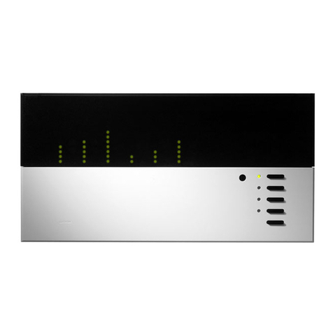
Grafik Eye 3000 Series Assembly instructions

LUTRON
PLEASE READ
®3000 Series
Installer’s Guide
Control Unit Models 3100 and 3500
LUTRON-Quality Systems
Registered to ISO 9001
Section 1: Introduction
GRAFIK Eye®3000 Series Control Unit . . . . . . . . . . . . . . . . . . . . . . . . . . . . . . . . . . . . . . . . . . 2
System Communications and Capacities . . . . . . . . . . . . . . . . . . . . . . . . . . . . . . . . . . . . . . . . 3
Section 2: Installing a GRAFIK Eye®Control Unit
Step 1: Test the Loads for Short Circuits . . . . . . . . . . . . . . . . . . . . . . . . . . . . . . . . . . . . . . . . 4
Step 2: Turn the Power OFF . . . . . . . . . . . . . . . . . . . . . . . . . . . . . . . . . . . . . . . . . . . . . . . . . . 4
Step 3: Mount the Wallbox . . . . . . . . . . . . . . . . . . . . . . . . . . . . . . . . . . . . . . . . . . . . . . . . . . . 5
Step 4: Connect the Line Voltage/Mains Cables to the Control Unit . . . . . . . . . . . . . . . . . . . . 5
Step 5: Connect PELV (Class 2: USA) Cable to the Control Unit — Optional . . . . . . . . . . . . . 6
Step 6: Mount the Control Unit . . . . . . . . . . . . . . . . . . . . . . . . . . . . . . . . . . . . . . . . . . . . . . . . 7
Step 7: Test the Control Unit. . . . . . . . . . . . . . . . . . . . . . . . . . . . . . . . . . . . . . . . . . . . . . . . . . 7
Step 8: Connect the Wallstations — Optional . . . . . . . . . . . . . . . . . . . . . . . . . . . . . . . . . . . . . 8
Step 9: Connect Other Accessories — Optional . . . . . . . . . . . . . . . . . . . . . . . . . . . . . . . . . . . 8
Step 10: Connect Multiple Control Units — Optional. . . . . . . . . . . . . . . . . . . . . . . . . . . . . . . . 9
Special Mounting Considerations . . . . . . . . . . . . . . . . . . . . . . . . . . . . . . . . . . . . . . . . . . . . . . 9
Installing an External Power Supply. . . . . . . . . . . . . . . . . . . . . . . . . . . . . . . . . . . . . . . . . . . . .10
Section 3: Programming a GRAFIK Eye®Control Unit
Control Unit Buttons and Indicators. . . . . . . . . . . . . . . . . . . . . . . . . . . . . . . . . . . . . . . . . . . . .11
Entering and Exiting Setup Mode . . . . . . . . . . . . . . . . . . . . . . . . . . . . . . . . . . . . . . . . . . . . . .11
Identifying the Load Type for Each Zone . . . . . . . . . . . . . . . . . . . . . . . . . . . . . . . . . . . . . . . . .12
Programming Scenes . . . . . . . . . . . . . . . . . . . . . . . . . . . . . . . . . . . . . . . . . . . . . . . . . . . . . . .14
Adjusting High or Low End Trim . . . . . . . . . . . . . . . . . . . . . . . . . . . . . . . . . . . . . . . . . . . . . . .17
Selecting the Save Mode You Want to Use. . . . . . . . . . . . . . . . . . . . . . . . . . . . . . . . . . . . . . .17
Section 4: Using the GRAFIK Eye®Control Unit
Selecting Scenes. . . . . . . . . . . . . . . . . . . . . . . . . . . . . . . . . . . . . . . . . . . . . . . . . . . . . . . . . . .18
Temporarily Adjusting Light Levels and Shade Positions . . . . . . . . . . . . . . . . . . . . . . . . . . . .18
Setting Up System Communications . . . . . . . . . . . . . . . . . . . . . . . . . . . . . . . . . . . . . . . . . . . .20
Appendix A: Troubleshooting . . . . . . . . . . . . . . . . . . . . . . . . . . . . . . . . . . . . . . . . . . . . . . . . . 22
Warranty. . . . . . . . . . . . . . . . . . . . . . . . . . . . . . . . . . . . . . . . . . . . . . . . . . . . . . . . . . . . . . . . . 23
Contact Information . . . . . . . . . . . . . . . . . . . . . . . . . . . . . . . . . . . . . . . . . . . . . . . . . . . . . . . . 24
This installer’s guide explains how to install and program a GRAFIK Eye 3000 Series control unit. Use this guide
in conjunction with installation instructions supplied separately with other GRAFIK Eye 3000 Series products.
R
Chinese
English Español Français Português NederlandsDeutsch Italiano

2 GRAFIK Eye®3000 Series Control Unit Installer’s Guide
R
Section 1:
Introduction
This section of the installer’s guide introduces the GRAFIK Eye 3000 Series lighting system
and control unit. This section also describes system communications and capacities. Read this
Introduction carefully before proceeding to the installation instructions beginning on page 4.
GRAFIK Eye®3000 Series Control Unit
The GRAFIK Eye is part of a lighting control system that enables you to create customized
scenes and control lighting and shade zones.
The control unit is the centerpiece of the lighting control system. The control unit provides:
•Setup of lighting and shade control scenes using buttons on
the control unit.
•Pushbutton recall of four preset scenes, plus OFF.
•12 additional scenes stored in the control unit, which are
accessible via optional wallstations and other control devices.
•Control of 2, 3, 4, or 6 zones.
•Smooth light level fading between scenes.
•Lockout options to prevent accidental changes.
•A built-in infrared receiver for operation with an optional remote control.
All of this can be accomplished on a single control unit. Up to 8 control units can be connected
together along with wallstations, sensors, and other control interfaces to enlarge the system and
add additional control functions.
Additional features available with a 3500 model are accessed through PC control and include:
•Lighting level increments of 1%
•Virtual control through LiaisonTM software
•Shade control through RS232 interface
M S
FADE TEMPORARY
MASTER
ZONES
ZONE 5 ZONE 6ZONE 3 ZONE 4ZONE 1 ZONE 2
Model Numbers and Ratings
Sources/Load Types
Control units can control incandescent, halogen (tungsten), magnetic low-voltage, and neon/
cold cathode load types. Electronic low-voltage and fluorescent load types, as well as shades,
can be controlled with appropriate interfaces.
Model Number Voltage Ratings
50/60 Hz Unit Maximums Zone Ranges
2 Zones
GRX-3102, GRX-3502 120 V~1200 W/VA 25-800 W
GRX-3102-CE, GRX-3502-CE 230 V~1600 W/VA 40-800 W
GRX-3102-AU, GRX-3502-AU 220-240 V~1600 W/VA 40-1200 W
GRX-3102-JA, GRX-3502-JA 100 V~1050 W/VA 25-600 W
3 Zones
GRX-3103, GRX-3503 120 V~1500 W/VA 25-800 W
GRX-3103-CE, GRX-3503-CE 230 V~2300 W/VA 40-800 W
GRX-3103-AU, GRX-3503-AU 220-240 V~2400 W/VA 40-1200 W
GRX-3103-JA, GRX-3503-JA 100 V~1250 W/VA 25-600 W
4 Zones
GRX-3104, GRX-3504 120 V~2000 W/VA 25-800 W
GRX-3104-CE, GRX-3504-CE 230 V~2300 W/VA 40-800 W
GRX-3104-AU, GRX-3504-AU 220-240 V~3000 W/VA 40-1200 W
GRX-3104-JA, GRX-3504-JA 100 V~1600 W/VA 25-600 W
6 Zones
GRX-3106, GRX-3506 120 V~2000 W/VA 25-800 W
GRX-3106-CE, GRX-3506-CE 230 V~2300 W/VA 40-800 W
GRX-3106-AU, GRX-3506-AU 220-240 V~3000 W/VA 40-1200 W
GRX-3106-JA, GRX-3506-JA 100 V~1600 W/VA 25-600 W

GRAFIK Eye®3000 Series Control Unit Installer’s Guide 3
R
Factory Presets
Lutron ships each control unit with the following factory presets (A- mode). In this mode,
control units and lighting wallstations communicate with no additional programming.
Accessories
Depending on the size and requirements of the lighting system, control units can be configured
to work with a variety of optional accessories, including:
• Low-voltage wallstations. Wallstations, shade controllers, infrared (IR) sensors and receivers,
and door-jamb controls.
• Control interfaces. Contact closure devices, RS232 and Ethernet digital communications.
astronomic timeclock, and programming interface for GRAFIK Eye LiaisonTM software.
• Load interfaces. Required for any loads exceeding the maximum zone capacity (see page 2),
as well as Lutron 3-wire fluorescent dimming ballasts, electronic low-voltage lighting, and 277
V loads.
For part numbers and additional information on GRAFIK Eye 3000 Series accessories, visit
www.lutron.com.
System Communications and Capacities
PELV (Class 2: USA) cable can be used to connect GRAFIK Eye 3000 control units,
wallstations, and other accessories. You can link up to 8 control units to control up to 48
zones, and add up to 16 wallstations and 8 shade controllers (SG-SVC) for a total of 32 control
points. Note that wallstations control scenes (which can include light and shade settings);
shade controllers control only shades.
PELV (Class 2: USA) Cables
If your lighting system uses wallstations and/or multiple control units, PELV (Class 2: USA)
wiring is needed to supply power and carry communications between the control units and the
wallstations. PELV (Class 2: USA) wiring is also needed to connect other accessories.
Use properly certified PELV (Class 2: USA) cable. Each twisted pair in the PELV (Class 2: USA)
wiring link should consist of two #18 AWG (1.0 mm2 ) stranded conductors.
• One pair is for the low-voltage power wiring.
• The second pair is for a data link (up to 2000 ft/610 m long).
Note: Lutron offers a one-cable, low-voltage solution: P/N GRX-CBL-346S (non-plenum) or
GRX-PCBL-346S (plenum). Check availability and applicable electrical codes in your area.
In countries that abide by the IEC regulations, PELV is commonly referred to as Protective Extra-
Low Voltage. A PELV circuit is a grounded circuit in which the voltage cannot exceed 50 V or 120 V
ripple-free. The power source must be supplied by a safety isolating transformer or equivalent.
Recommended unshielded cables include:
• For non-plenum installations, use (2) Belden 9470, (1) Belden 9156, or (2) Liberty 181P/2C-EX-
GRN, or equivalent.
• For plenum installations, use (2) Belden 82740, or equivalent.
In Europe, acceptable types of cable include HAR certified cable with insulated cores
enclosed in a sheath. This cable must bear the appropriate certification mark pertaining to
national wiring rules for fixed installations. If certified cable with insulated cores enclosed in a
sheath is used for the power cables, the PELV wiring can be any of the cables listed above.
Setting Factory Preset
Address Not addressed (set to factory default A-)
Load type All zones set to incandescent
Scene 1 100% intensity for all zones
Scene 2 75% intensity for all zones
Scene 3 50% intensity for all zones
Scene 4 25% intensity for all zones
Scenes 5-16 100% intensity for all zones
OFF (scene 0) All zones OFF
Fade times 3 seconds between all scenes; 10-second fade time to OFF
Fade time from OFF 4 seconds to any scene (not adjustable)
Save mode Sd (save by default)
Note: Scene fade time affects lights but not shades; shades move immediately to their
programmed level.

4 GRAFIK Eye®3000 Series Control Unit Installer’s Guide
R
Section 2:
Installing a GRAFIK Eye®Control Unit
This section explains how to install a GRAFIK Eye control unit and make sure it is properly
operating all connected loads.
DANGER! GRAFIK Eye 3000 Series control units must be installed by a qualified electrician
in accordance with all applicable regulations and building codes. Improper wiring can result
in personal injury or damage to control units or other equipment. Always turn off circuit
breaker or remove main fuse from power line before doing any work. To avoid overheating
and possible damage to equipment, do not install dimming devices to dim receptacles,
motor-operated appliances, or fluorescent lighting not equipped with Lutron Hi-lume®,
Eco-10TM, or Tu-Wire®electronic dimming ballasts, or devices approved for your location.
In dimmed magnetic low-voltage circuits, you can prevent transformer overheating and fail-
ure by avoiding excessively high current flow: Do not operate control units with any lamps
removed or burned out; replace any burned out lamps immediately; use only transformers
that incorporate thermal protection or fused primary windings. Control units are designed
for residential and commercial use, for indoor use only.
Important Information about Loads and Wallboxes
GRAFIK Eye 3000 Series control units can control incandescent, halogen (tungsten), magnetic
low-voltage, and neon/cold cathode load types. Many dimmable fluorescent, electronic low-
voltage, and shade loads can be controlled with appropriate interfaces.
• All electronic low-voltage (ELV) lighting used with the electronic low-voltage interface must be
rated for reverse phase-control dimming, also known as trailing edge dimming. Before
installing an ELV light source, verify with the manufacturer that their transformer can be dimmed.
When dimming, an electronic low-voltage interface MUST be used with the control unit.
• Contact Lutron or refer to your job drawings for information on other product interfaces.
• Not all zones on the control unit need to be connected; however, connected zones must have a
load of at least 25 W (40 W for AU and CE models).
• No zone may be loaded with more than 800 W (1200 W for AU models).
• See page 2 for maximum unit ratings.
Step 1: Test the Loads for Short Circuits
CAUTION! Before connecting the loads to the control unit, test the loads for short-circuits.
1. Turn power OFF at the circuit breaker or fuse box.
2. Connect a standard light switch between the live lead and load wire to
test the circuit.
3. Turn power ON and check for short or open circuits. If load does not
operate, the circuit is open. If the breaker/MCB trips (fuse blows or
opens), a load short may exist. Correct short or open circuits and test
again.
Step 2: Turn the Power OFF
CAUTION! Before continuing with the installation, make sure the power is turned OFF at
the circuit breaker or fuse box. Do not perform any wiring with the power ON.
Hot/Live
Neutral
Switch
Load

GRAFIK Eye®3000 Series Control Unit Installer’s Guide 5
R
Step 3: Mount the Wallbox
1. Mount a standard U.S. wallbox on a dry, flat indoor surface that is accessible and allows for
system programming and operation. See the table below for the recommended wallbox for
each model.
Use a minimum depth of 2 3/4 in. (68 mm), preferably 3 1/2 in. (87 mm). Allow at least 4 1/2 in.
(110 mm) clearance above and below the faceplate to ensure proper heat dissipation. Allow
1 in. (25 mm) for faceplate overhang on all sides.
NOTE: For mounting in a panel, refer to page 10.
Step 4: Connect the Line Voltage/Mains Cables to the Control Unit
Important Wiring Information
• Use properly certified cable for all line voltage/mains cables.
• Proper short-circuit and overload protection must be provided at the distribution panel. You
can use up to a 20 A (16 A for AU, and 10 A for CE models) maximum circuit breaker/MCB or
equivalent (tripping curve C according to IEC60898/EN60898 is recommended) with adequate
short-circuit breaking capacity for your installation.
• Install in accordance with all local and national electrical codes.
CAUTION! Do not connect line voltage/mains cable to PELV (Class 2: USA) terminals.
• Earth/ground terminal connection must be made as shown in wiring diagrams on page 6.
• Do not mix different load types on the same zone!
• See page 3 for devices that require interfaces. Wire as specified in the interface documentation.
• The line voltage/mains cables should be separated from the PELV (Class 2: USA) cable and
terminal block by at least 1/4 in. (7 mm).
To connect the line voltage/mains cables to the control unit:
1. Remove the control unit’s cover and hinged faceplate by pulling
outward at each corner.
2. Strip 1/2 in. (12 mm) of insulation off the line voltage/mains cables in
the wallbox.
3. Connect the line voltage, ground, and load wires to the appropriate
terminals on the back of the control unit, as shown on page 6 for
GRX, GRX-AU and GRX-CE models.
The recommended installation torque is 9.0 in.-lbs. (1.0 N•m) for line voltage connections and
10 in.-lbs. (1.3 N•m) for the earth/ground connection. Each power terminal can accept up to
two #12 AWG (2.5 mm2 ) wires. This does not apply to the PELV (Class 2: USA) terminal block.
230V
˜
LUTRO N
50/60Hz
LOADPERZ O N E: 40-8 00W
MAXUNIT LOAD:10A , 230 0W
PresetLigh tin g Control
LIVETER MIN A LS ATREA R
DON O T WIRE LIV E
U.K.071-702-0657
U.S.
A.(610)282 -3800
COOPERSBURG,PA USA18036
GRX-3104-CE
UP
Madein U .S.A .
12V
SELVOUTPU T
!
CBE5
145-049
GRX-Z
NOTE: Single-gang wallbox P/N 241218; 4-gang wallbox P/N 241400.
2. Pull the line voltage/mains cables into the wallbox using
the rearmost knockouts. This will provide the most
clearance when mounting the control unit.
If the control unit will be connected to wallstations and/
or additional control units, also pull the PELV (Class 2:
USA) cabling into the wallbox using the remaining
rearmost knockout (refer to page 7). Use recommended
cable as specified in “PELV (Class 2: USA) Cables” on
page 3.
3.5 in.
(87 mm)
7.9 in.
(200 mm)
3.75 in.
(95 mm)
Control Unit Model 100-120 V 230 V (CE) 220-240 V (AU)
GRX-3102/3502 2-gang wallbox 4-gang wallbox 2-gang wallbox
or two single-gang or two single-gang
wallboxes wallboxes
GRX-3103/3503 3-gang wallbox 4-gang wallbox 3-gang wallbox
or three single-gang or three single-gang
wallboxes wallboxes
GRX-3104/3504 4-gang wallbox 4-gang wallbox 4-gang wallbox
GRX-3106/3506 4-gang wallbox 4-gang wallbox 4-gang wallbox

6 GRAFIK Eye®3000 Series Control Unit Installer’s Guide
R
Line Voltage/Mains Connections for GRX-CE Models* (6-Zone Unit Shown)
N
L
SSA
GRX-3106-CE
ZONE: 40 - 800 W/VA
10 A 2300 W/VA
Coopersburg, PA 18036 USA
:
2 2.5 mm2
Earth/ground from distribution panel
Neutral from
distribution panel
Input power from
distribution panel
Hot/
Live
N
Distribution panel
Step 5: Connect PELV (Class 2: USA) Cable to the
Control Unit — Optional
If your lighting system uses wallstations and/or multiple control units, PELV (Class 2: USA)
wiring is needed to supply power and carry communications between the control units and the
wallstations.
Important Wiring Information
• Lutron requires that you connect (daisy-chain) control units and wallstations with two twisted
pairs for operation. Each twisted pair in the PELV (Class 2: USA) wiring link should consist of
two #18 AWG (1.0 mm2) stranded conductors.
• Use properly certified PELV (Class 2: USA) cable. For a description of recommended cable
types, refer to “PELV (Class 2: USA) Cables” on page 3.
• Install in accordance with all local and national electrical codes.
• Wallstation circuits are classified as Class 2 (USA) and PELV (IEC) circuits. Unless otherwise
specified, the voltages do not exceed 24 V or 15 V . As Class 2 circuits, they comply
with the requirements of NFPA 70®, National Electrical Code®(NEC®). As PELV circuits, they
comply with the requirements of IEC 60364-4-41, VDE 0100 Part 410, BS7671:1992, and other
equivalent standards. External circuits connected to input, output, RS232, Ethernet, DMX512,
and other communication terminals or wallstations, must be supplied from a Listed Class 2
source or comply with the requirements for PELV circuits as applicable in your country.
• The control unit’s low-voltage PELV (Class 2: USA) circuit is 12 V .
• The PELV (Class 2: USA) cable and terminal block should be separated from the line voltage/
mains cables by at least 1/4 in. (7 mm).
* For phase-to-phase and delta-feed wiring, contact Lutron.
2 2.5 mm2
2 2.5 mm2
2 2.5 mm2
2 2.5 mm2
2 2.5 mm2
2 2.5 mm2
ZONE 4
ZONE 6
HOT/LIVE
SSA
CU WIRE ONLY
ZONE 2
Class 2
1 2 3 4
ZONE 3
ZONE 5
NEUTRAL
ZONE 1
USA
CLASS 2
IEC
PELV
Hot/
Live
N
Load 2
Load 4
Load 6
Load 1
Load 3
Load 5
Distribution
panel
Neutral from distribution panel
Input power from
distribution panel
Earth/ground from distribution panel
2 #12 AWG
Line Voltage/Mains Connections for GRX* and GRX-AU* Models (6-Zone Unit Shown)
2 #12 AWG
2 #12 AWG
2 #12 AWG
2 #12 AWG
2 #12 AWG
2 #12 AWG
Load 2
Load 4
Load 6
Load 1
Load 3
Load 5

GRAFIK Eye®3000 Series Control Unit Installer’s Guide 7
R
To connect the PELV (Class 2: USA) wires to the control unit:
1. Strip 1 in. (25 mm) of insulation from the
PELV (Class 2: USA) cable in the wallbox.
2. Strip 3/8 in. (9.5 mm) of insulation from each
wire.
3. Connect the twisted pair for low-voltage
power wiring to terminal 1 (common) and
terminal 2 (12 V ) on the control unit.
NOTE: You will daisy-chain this low-voltage
power wiring to wallstations and/or other
control units. Refer to pages 8 and 9.
4. Connect the twisted pair data link to terminal
3 (MUX) and terminal 4 (MUX) of the control
unit.
NOTE: You will daisy-chain this data link to
wallstations and/or other control units. Refer
to pages 8 and 9.
5. If shielded wire is used, connect the drain
wires to each other or to terminal D on the
wallstation, if present. Do NOT connect drain
wires to earth/ground.
WARNING! Make sure no bare wire
is exposed after making connections.
The recommended installation torque is
3.5 in.-lbs. (0.4 N•m) for PELV (Class
2: USA) connections.
1
2
3
4
Line voltage/mains
cable
PELV (Class 2:
USA) terminals
PELV (Class 2:
USA) cable
1.0 in.
(25 mm)
3/8 in.
(9.5 mm)
Line voltage/mains
cable
Step 7: Test the Control Unit
1. Turn the power ON.
2. Press the SCENE 1 button on the front of the
control unit. The Scene 1 LED will light.
3. Press the 5or 6button for each zone and
verify that the control unit is controlling all
connected loads. If not, refer to Appendix
A: Troubleshooting, or call Lutron Technical
Support.
M S
FADE TEMPORAR Y
MASTER
ZONES
ZONE 5 ZONE 6ZONE 3 ZONE 4ZONE 1 ZONE 2
SCENE 1
button
OFF
ZONE intensity
raise and lower buttons Scene 1 LED
Step 6: Mount the Control Unit
1. Mount the control unit in the wallbox as shown
using the four screws provided.
NOTE: Make sure the PELV (Class 2: USA)
cable and terminal block remain separated
from the line voltage/mains cables when the
control unit is mounted in the wallbox.
2. Reattach the cover and faceplate to the
control unit by pushing inward at each corner.
2 pair #18 AWG
(1.0 mm2)

8 GRAFIK Eye®3000 Series Control Unit Installer’s Guide
R
Step 8: Connect the Wallstations — Optional
If your lighting system uses wallstations, make the appropriate connections at the wallstation
using PELV (Class 2: USA) cabling.
NOTE: For procedures on how to install and address
wallstations, refer to the separate instructions included with
each device. Wallstations must be installed by a qualified
electrician in accordance with all local and national electrical
codes.
1. Daisy-chain the PELV (Class 2: USA) twisted pair for low-
voltage power wiring from the control unit to terminal
1 (common) and terminal 2 (12 V ) on up to three
wallstations.
2. Terminate the terminal 2 connection so that the control unit
supplies power to a maximum of three wallstations.
NOTE: To power more than three wallstations from one
control unit, install an external 12 V power supply (15 V
for CE/AU models). Refer to page 10 for instructions.
3. Daisy-chain the PELV (Class 2: USA) twisted pair data
link from the control unit to terminal 3 (MUX) and terminal
4 (MUX) on each wallstation.
WARNING! Make sure no bare wire is exposed after
making connections. The recommended installation
torque is 3.5 in.-lbs. (0.4 N•m) for PELV (Class 2: USA)
connections.
4
3
2
1
Each terminal can accept
2 #18 AWG (1.0 mm2) wires
PELV
(Class 2: USA)
power wiring:
2: 12 V
1: common
2 twisted pairs
#18 AWG
(1.0 mm2)
Data link:
4: MUX
3: MUX
4
3
2
1
4
3
2
1
4
3
2
1
ZONE 4
ZONE 6
HOT/LIVE
SSA
CU WIRE ONLY
ZONE 2
Class 2
1 2 3 4
ZONE 3
ZONE 5
NEUTRAL
ZONE 1
USA
CLASS 2
IEC
PELV
Each
terminal
can accept
2 #18 AWG
(1.0 mm2)
wires
PELV (Class 2: USA)
power wiring:
2: 12 V
1: common
Wallstation Wallstation Wallstation
GRAFIK Eye
3000 control unit
Control Unit Connected to Three Wallstations
Maximum of 1000 ft. (300 m) between the
GRAFIK Eye control unit and the third wallstation.
For longer distances or to power more than three
wallstations, see page 10.
Step 9: Connect Other Accessories — Optional
If your lighting system uses accessories other than wallstations (shade controllers, interface
devices, and power boosters), make the connections at the accessory using the appropriate
wiring.
For procedures on how to install and connect accessories, refer to the separate instructions
provided with each accessory.
Important Wiring Information
• Accessories must be installed by a qualified electrician in accordance with all local and national
electrical codes.
• Use properly certified cable as described in the instructions shipped with the accessory.
Data link:
4: MUX
3: MUX

GRAFIK Eye®3000 Series Control Unit Installer’s Guide 9
R
4
3
2
1
4 3 2 1
1 2 3 4
1 2 3 4
4 3 2 1
4
3
2
1
4
3
2
1
4
3
2
1
4
3
2
1
4
3
2
1
4
3
2
1
4
3
2
1
4
3
2
1
4
3
2
1
4
3
2
1
4
3
2
1
4
3
2
1
4
3
2
1
A1
A2
A3
A1 powers aonly—
terminal 2 connection
terminates at a.
A2 and A3
have their
own power
supplies—no
terminal 2
connection.
b
c
d
e
f
g
A4
A3 powers b, cand d.
Total PELV (Class 2: USA)
wiring length is 2000 ft.
(600 m).
A4 powers
e, f, and
g—
no
terminal 2
connection
between d
and e.
a
System Maximums: Up to 8 Control Units and 16 Wallstations
and 8 Shade Controllers
Special Mounting Considerations
Wallbox Mounting and Spacing
When mounting multiple control units or interface devices, be sure to follow spacing and
ventilation requirements to ensure proper operation.
• All control units MUST be mounted in a standard
U.S. wallbox. (For mounting procedures, refer to
page 5.)
• All control units, power boosters, fluorescent
interfaces, and electronic low-voltage interfaces MUST
have 4 1/2 in. (110 mm) of space above and below
the faceplate to dissipate the heat caused by normal
operation. Allow 1 in. (25 mm) for faceplate overhang
on all sides.
CAUTION! GRAFIK Eye 3000 Series control
units and interface devices, such as NGRX-PB,
dissipate heat when operating. Obstructing
these units can cause malfunction to both the
control unit and the interface device if ambient
temperature does not remain between 32–104 °F
(0–40 °C).
Limited by physical size of unit.
Must be able to open front cover.
4 1/2 in. (110 mm) minimum
Step 10: Connect Multiple Control Units — Optional
If your lighting system has multiple control units, connect them using PELV (Class 2: USA)
cabling as described here.
1. Daisy-chain the PELV (Class 2: USA) cabling to terminal 1, terminal 2, terminal 3, and terminal 4
on all control units and wallstations.
NOTE: To power more than three wallstations from one control unit, install an external 12 V
or 15 V power supply. Refer to page 10 for instructions.
2. Since each control unit has its own power supply, terminate the terminal 2 connection so that:
• Each control unit supplies power to a maximum of three wallstations.
• Each wallstation receives power from only one control unit.
WARNING! Make sure no bare wire is exposed after making connections. The recom-
mended installation torque is 3.5 in.-lbs. (0.4 N•m) for PELV (Class 2: USA) connections.

10 GRAFIK Eye®3000 Series Control Unit Installer’s Guide
R
4
3
2
1
4
3
2
1
3
2
1
4
Installing an External Power Supply
Install an external PELV (Class 2: USA) rated 12 V (15 V for CE/AU models) power supply if
you need to power 4 to 16 wallstations from a single control unit or if your wire lengths exceed
maximums. The power must be a regulated supply rated for at least 50 mA per wallstation on
the link.
Power supplies do not boost data line signals. The distance limitation for the data line is 2000 ft.
(610 m).
Make sure you review the manufacturer’s instructions before installing.
Lutron offers a 12 V transformer for 120 V applications. Please ask for P/N GRX-12VDC.
15 V power supply is approved for CE and AU models; 12 V is approved for all other
models.
Important Wiring Information
1. Connect the Common and Power wires from the power supply to Terminals 1 and 2 on all
wallstations. Do not connect this wire to any control units on the link. Be sure that the terminal 1
connection is made to all wallstations and control units.
2. Lutron recommends these maximum distances from the external 12 V power supply to the
sixteenth wallstation:
• #18 AWG (1.0 mm2 ) wire: 300 ft. (90 m).
• #12 AWG (2.5 mm2 ) wire: 1000 ft. (300 m).
Note that the allowable maximum distance depends on the number of wallstations in the system.
Refer to separate Application Note W14 or contact Lutron Technical Support for additional
information.
PELV (Class 2: USA) terminals
on back of unit
1 twisted pair
#18 AWG (1.0 mm2)
or larger 2 twisted pairs
#18 AWG (1.0 mm2) or larger
Wallstation Wallstation
16 wallstations
(maximum)
Common
12 V
1 #18 AWG
(1.0 mm2)
To power source
External PELV (Class 2: USA) rated power supply
Lutron P/N GRX-12VDC for 120 V applications
UK plug style TU-240-15DC-9-BL
European plug style TE240-15DC-9-BL
Mounting in a Panel
• The enclosure must be in accordance with all local
and national electrical codes.
• Lutron does not recommend using a door to enclose
the front of a panel, since this restricts airflow to the
control units and interface devices.
• If mounting multiple control units or interface devices
in an enclosure:
– Ambient temperature within an enclosure MUST
remain between 32–104 °F (0–40 °C).
– If not mounting in a metal enclosure, all units
MUST be mounted in a wallbox. Refer to
“Wallbox Mounting and Spacing” on page 9.
• To improve heat dissipation of interface units, (i.e.,
NGRX-PB, GRX-ELVI, etc.), remove the faceplate
from the unit.
CAUTION! GRAFIK Eye 3000 Series control
units and interface devices, such as NGRX-PB,
dissipate heat when operating. Obstructing
these units can cause malfunction to both the
control unit and the interface device if ambient
temperature does not remain between 32–
104 °F (0–40 °C).
4 1/2 in. (110 mm) minimum
ELV
interface
FDB
interface
Power
booster

GRAFIK Eye®3000 Series Control Unit Installer’s Guide 11
R
Section 3:
Programming a GRAFIK Eye®Control Unit
This section identifies buttons and indicators on a GRAFIK Eye 3000 Series control unit. This
section also explains how to enter setup mode, program a control unit, adjust the high and low
end trim, and select a save mode. Most programming operations are typically performed only
once, when the control unit is installed. Other operations, such as selecting scenes and making
temporary adjustments, are performed as needed to achieve the right lighting and shade effects.
For systems with multiple control units, refer to page 20 for addressing.
NOTE: Lutron ships each control unit with factory-set programming. For a description of the
factory presets, refer to page 3
Control Unit Buttons and Indicators
The setup codes include:
FADE TEMPORARY
MASTER
ZONES
ZONE 5 ZONE 6
M S
To enter (exit)
setup mode:
Press and
hold for
about three
seconds until
LEDs cycle
(stop cycling)
Scene LEDs
Use 5and 6to scroll through setup
codes (LS is the first code to display)
Entering and Exiting Setup Mode
You must enter setup mode to access the programming functions on the control unit.
To enter setup mode: Press and hold the SCENE 1 and OFF buttons for about three sec-
onds, until the scene LEDs start cycling. When the buttons are released, the LEDs should
continue to cycle.
In setup mode, the FADE window displays the first setup code available for programming. To
scroll up and down through the menu of setup codes, press the FADE 5or 6buttons.
To exit setup mode: Press and hold the SCENE 1 and OFF buttons for about three seconds,
until the scene LEDs stop cycling. The control unit returns to normal operating mode.
FADE TEMPORARY
MASTER
ZONES
ZONE 1 ZONE 2
M S
00
Hinged cover
Zone label
Light level/shade position
LED bar graph
ZONE raise/lower buttons
Infrared wireless
remote control receiver
Faceplate
FADE window (if ‘S’ is lit, time is
in seconds, if ‘M’ is lit, time is in
minutes)
MASTER raise/lower buttons
FADE buttons
SCENE buttons
Scene 1
Scene 2
Scene 3
Scene 4
OFF
Scene indicator LEDs
TEMPORARY ZONES button
Code Stands for Description
Sd Save modes Select from
several save
options (page 17).
Sc Scene Set up any of the
scenes, including
unaffected zones
(page 16).
A- Address Identify control
units for system
communications
(page 20).
LS Load Select Identify load types
(page 12).
HE High End Set high end trim
(page 17).
LE Low End Set low end trim
(page 17).

12 GRAFIK Eye®3000 Series Control Unit Installer’s Guide
R
Identifying the Load Type for Each Zone
A load refers to the type of lighting, shade, or interface device connected to the control unit.
Lutron ships control units with all zones set for incandescent/halogen (tungsten) lighting. If your
lighting system has non-incandescent loads, change each of those zones to the correct load type.
To identify the load type for each zone:
1. Enter setup mode. Press and hold the
SCENE 1 and OFF buttons for about three
seconds, until the scene LEDs cycle.
2. Check for LS in FADE window. LS is the
first code to display when you enter setup
mode. In LS mode, ZONE LEDs turn on from
top to bottom.
3. Set the load type for each zone. Press the
ZONE 5or 6button until the ZONE LEDs
match the load type connected to each zone.
Refer to the following table for each load type
and its corresponding LEDs.
4. Exit setup mode. Press and hold the SCENE
1 and OFF buttons for about three seconds,
until scene LEDs stop cycling.
In the sample 6-zone control unit shown here:
• Zone 5 is set for incandescent, magnetic
low-voltage, or HP dimming module.
• Zone 6 is set for neon/cold cathode.
FADE TEMPORARY
MASTER
ZONES
ZONE 5 ZONE 6
M S
3
2
1 4
,
Set the load type for each zone
Check for
LS
Enter
(exit)
setup
mode
Zone LEDs
To set this load type... Select this
LED display
Important Notes
Switching (non-dim)
Loads
Non-dim
(last on, first off) *
Use non-dim for any lights to be switched ON and
OFF only—not dimmed (unless using HP dimming
module) when fading between scenes. This load will
be the last to switch on and the first to switch off.
Fluorescent non-dim loads with electronic or mag-
netic ballasts must use a GRX-TVI Interface and
be set for non-dim mode, or use an HP 2•4•6TM
dimming module and be set for HP 2•4•6
dimming module loads. Contact closure outputs.
Non-dim
(first on, first off) * Use non-dim for any lights to be switched ON
and OFF only—not dimmed (unless using HP
dimming module) when fading between scenes.
This load will be the first to switch on and the first
to switch off.
Fluorescent non-dim loads with electronic or mag-
netic ballasts must use a GRX-TVI Interface and
be set for non-dim mode, or use an HP 2•4•6
dimming module and be set for HP 2•4•6
dimming module loads. Contact closure outputs.
Motorized Shades
AC shade* * AC shades zones are factory set to unaffected
in each scene. To program shade positions for a
scene, refer to pages 14 and 15.
GRAFIK Eye 3000 control units must be
addressed to control shades. To assign
addresses, refer to page 20.
Sivoia® QED
shade*
*Sivoia QED shade zones are factory set to
unaffected in each scene. To program shade
positions for a scene, refer to pages 14-16.
GRAFIK Eye 3000 control units must be
addressed to control shades. To assign
addresses, refer to page 20.
Blinking
LED
Blinking
LED

GRAFIK Eye®3000 Series Control Unit Installer’s Guide 13
R
To set this load type... Select this
LED display
Important Notes
Dimming Loads
Incandescent/halogen
(tungsten) * Use for tungsten filament lamps.
NOTE: This is the factory preset load type for each
zone.
Magnetic low-voltage * Use for magnetic transformer low-voltage lighting.
HP 2•4•6TM loads
(120 V supply only) * Set all zones connected to HP dimming modules
as shown—no matter what load type they are
(including non-dim or switching). The HP can be
used to switch non-capacitive ballasts. To fine-
tune the dimming of these “HP-powered” zones,
you must adjust high and low end trim on the HPs
as described in the instructions supplied with the
unit. Do NOT use HPs with generator-supplied
line/mains voltage.
GRX-ELVI loads
(Electronic low-
voltage)*
* All electronic low-voltage (ELV) lighting used with
an electronic low-voltage interface (ELVI) must
be rated for reverse phase control/trailing edge
dimming. Refer to the documentation for your
interface.
GRX-FDBI or
GRX-TVI loads
(Lutron 3-wire
fluorescent)*
* Zones set for Lutron Hi-lume or Eco-10
fluorescent lighting must have GRX-FDBI or
GRX-TVI fluorescent interfaces. Contact Lutron
for more information. Refer to the documentation
for your interface.
Tu-Wire®compact
fluorescent
*Tu-Wire compact fluorescent does not require a
fluorescent dimming ballast interface (FDBI). This
load type is not available in GRX-CE models.
Neon/cold cathode * Use for neon or cold cathode lighting.
*Interface required; contact Lutron Technical Support for details.
Legend:
LED lit
LED off

14 GRAFIK Eye®3000 Series Control Unit Installer’s Guide
R
Programming Scenes
Scenes are preset lighting levels, fade times, and shade positions stored in the control unit. (Note
that AC shades can be programmed in a scene as only fully open, fully closed, or unaffected;
Sivoia QED shades can be programmed at any preset level or unaffected.) You can program up
to 16 scenes, plus OFF (scene 0). Any time a scene button is pressed or input from an optional
control interface is received, the system activates the desired scene.
To program scenes 1 through 4 using
save mode:
1. Select a scene. Press the SCENE button for the
scene you want to program.
2. Set the scene settings for each zone.
For lighting zones, press the ZONE 5or 6
button to set the right visual intensity for this
scene.
For AC shade zones, press the ZONE 5or 6
button until the ZONE LEDs match the right
shade position for this scene. See the illustration
below.
For Sivoia QED shade zones, press the
ZONE 5or 6button until the ZONE LEDs
match the right shade position for this scene.
See the illustration below.
NOTE: To quickly set a shade zone to fully open
or fully closed, press and hold the ZONE 5or 6
button for about three seconds.
For unaffected zones, press and hold the
ZONE 6button until all its LEDs go out and
the middle three LEDs light (this may take up
to 10 seconds). This zone’s settings will not be
affected when this scene is selected.
To reprogram an unaffected zone as
affected, follow the steps above. Then press the
ZONE 5button for about three seconds until
the middle three ZONE LEDs are no longer lit.
Program the zone’s settings.
FADE TEMPORARY
MASTER
ZONES
ZONE 5 ZONE 6
ZONE
M S
2
1
Set the scene settings for each zone
Select a
scene
Programming Scenes 1 through 4 (Save Mode)
If the control unit is set to the factory default Sd save mode (adjustments to zone settings are
saved for the current scene), you can program scenes 1 through 4 without entering setup mode.
NOTE: To program scenes using setup mode, refer to page 16. To select a save mode, refer to
page 17.
LED Displays for Programming Scene Settings
Lighting Zones AC Shade Zones Sivoia QED Shade Zones
Off Fully open Fully open Preset 1
On 50% Fully closed Fully closed Preset 2
On 100% Preset 3
Unaffected Unaffected Unaffected
Scene 1
Scene 2
Scene 3
Scene 4
OFF
Legend:
LED lit
LED off

GRAFIK Eye®3000 Series Control Unit Installer’s Guide 15
R
3. Set the fade-in time for this scene (does not
apply to shades). Press the FADE 5or 6button
to make the fade-in time anything from 0–59
seconds or 1–60 minutes.
The Mand Sindicators under the FADE window
show whether fade is “M”inutes or “S”econds.
To set the fade in minutes, press the FADE 5
button to scroll through 1–59 seconds to 1 to 60
minutes, then M lights. Fade is now expressed
in minutes. To get back to seconds, press
the FADE 6button until the window shows
“S”econds.
4. Repeat steps 1 through 3 to set up each of the
remaining scenes.
To set a Fade-to-OFF time, press the OFF
scene button, then set the seconds or minutes to
fade to OFF from this scene.
FADE TEMPORARY
MASTER
ZONES
ZONE 5 ZONE 6
ZONE
M S
3
Set scene’s
fade-in time

ZONE 1 ZONE 2
M S
2
3
4
1
FADE TEMPORARY
MASTER
ZONES
5
6
,
Programming Scenes 1 through 16 (Setup Mode)
You can program any scene using setup mode. If your lighting system requires more than 4
scenes, scenes 5 through 16 must be programmed using setup mode.
NOTE: To program scenes 1 through 4 using Sd save mode, refer to page 14.
Program
lighting or
shade scene
settings for
each zone
To program scenes using setup mode:
1. Enter setup mode. Press and hold the
SCENE 1 and OFF buttons for about
three seconds until the scene LEDs start
cycling.
2. Select Sc (scene setup) by pressing the
FADE 5button twice. Sc and 1(scene 1)
will alternately flash in the FADE window.
3. Select scene. Press the MASTER 5
or 6button to select the number of the
scene to be programmed (1 through 15;
0 is the OFF scene).
4. Program scene settings for each zone.
For lighting zones, press the ZONE 5
or 6button to set the zone intensity.
(GRX-3500 units will display exact per-
centage light output; press again to adjust
light levels in 1% increments.)
For AC shade zones, press the
ZONE 5or 6button until the ZONE
LEDs match the right shade position for
this scene. See the illustration on page 14.
For Sivoia QED shade zones, press
the ZONE 5or 6button until the ZONE
LEDs match the right shade position for
this scene. See the illustration on page 14.
For unaffected zones, press and hold
the ZONE 6button until all its LEDs go
out and the middle three LEDs light (this
may take up to 10 seconds). This zone’s
settings will not be affected when this
scene is selected.
To reprogram an unaffected zone as
affected, follow the steps above. Then
press the ZONE 5button for about three
seconds until the middle three ZONE
LEDs are no longer lit. Program the
zone’s settings.
5. Set the scene’s fade-in time. Press
and hold the TEMPORARY ZONES
button. The current fade-in time will be
displayed. Adjust using the FADE 5or 6
button while still holding the TEMPORARY
ZONES button. (Fade time does not apply
to shade zones.)
6. Exit setup mode. Press and hold the
SCENE 1 and OFF buttons until the LEDs
stop cycling.
Select flashing Sc/1
Set scene’s
fade-in time
Select
scene
Enter
(exit)
setup
mode
ZONE 5 ZONE 6
M S
FADE TEMPORARY
MASTER
ZONES
4
To set unaffected zone,
press ZONE 6twice
and then hold until mid-
dle three LEDs light
16 GRAFIK Eye®3000 Series Control Unit Installer’s Guide
R

Adjusting High or Low End Trim
High and low end trim settings limit the maximum and minimum output of a dimming zone. Trim
levels are set automatically when the load type is programmed. Change the high or low end trim
for a zone only if the default setting needs to be adjusted.
To adjust high or low end trim:
1. Enter setup mode. Press and hold the
SCENE 1 and OFF buttons for about three
seconds, until the scene LEDs start cycling.
2. Select HE (high end) or LE (low end).
Press the FADE 6button until HE or LE is
displayed in the FADE window.
For high end, all zones go to their highest
possible dim levels and all their LEDs are lit.
For low end, all zones go to their lowest possible
dim levels and only their bottom LED is lit.
NOTE: For shade zones, the middle three LEDs
are lit to indicate that they are unaffected. For
non-dim lighting zones, all LEDs are lit (for
high end) or OFF (for low end) and you cannot
adjust the high or low end trim.
3. Adjust zone’s trim setting. Press the
ZONE 5or 6button to raise or lower the
trim. Repeat this process for other zones that
require trim adjustments.
4. Exit setup mode. Press and hold SCENE 1
and OFF buttons until the scene LEDs stop
cycling.
Note: Setting low-end trim below the factory
default may cause some load types to flicker.
FADE TEMPORARY
MASTER
ZONES
ZONE 5 ZONE 6
M S
3
2
14
,
Adjust zone’s trim setting
Select HE
or LE
Enter
(exit)
setup
mode
To select the save mode you want to use:
1. Enter setup mode. Press and hold the
SCENE 1 and OFF buttons for about three
seconds until scene LEDs start cycling.
2. Select Sd. Press the FADE 5button until
Sd is displayed in the FADE window.
3. Select save mode. Press the MASTER 5
or 6button to scroll through the save
modes and select one. Refer to the save
mode descriptions in the table below.
4. Exit setup mode. Press and hold the
SCENE 1 and OFF buttons until scene LEDs
stop cycling.
FADE TEMPORARY
MASTER
ZONES
ZONE 5 ZONE 6
M S
23
14
,
Enter
(exit)
setup
mode
Select
save mode
Select Sd
Selecting the Save Mode You Want to Use
Save modes enable you to specify how buttons on the control unit work. For example,
adjustments to a zone’s settings can be temporary or saved for the current scene. Buttons can
also be disabled to prevent accidental changes.
The zone’s LED bar graph does
not change while you make trim
adjustments. The bar graph
remains set to its highest/lowest
level in this mode.
Code Stands for Description
Sd
Save by Default
Changes to a zone’s intensity/shade position or fade time are saved for
the current scene. To make temporary adjustments in Sd mode, refer to
page 18. Typical user: Home theater owner.
Sb
Save by Button
TEMPORARY ZONES LED is normally ON and all intensity/shade position and
fade changes are temporary unless the TEMPORARY ZONES LED is turned
OFF with the TEMPORARY ZONES button. Typical user: Restaurant manager.
Sn
Save Never
TEMPORARY ZONES LED is permanently ON and cannot be turned OFF. In
this mode, all intensity changes are temporary. Typical user: Lighting designer.
4S
Four Scenes
Allows only the four SCENE buttons, OFF button, IR receiver, and
MASTER 5or 6buttons to operate. All other buttons on the control unit
are disabled. Typical use: Rented meeting space.
bd
Button Disable
All buttons on the control unit are disabled. IR receiver and wallstations are
still functional. (Setup mode is still accessible by repeating Step 1.) Typical
use: Public space.
GRAFIK Eye®3000 Series Control Unit Installer’s Guide 17
R

Temporarily Adjusting Light Levels and Shade Positions
You can temporarily adjust the light level or shade position of a zone. Temporary adjustments
remain in effect only until a new scene selection occurs.
NOTE: For control units set to bd save mode (refer to page 17), temporary adjustments can be
made only using a wallstation, shade controller, or IR control.
To temporarily adjust all lighting
zones:
1. Press the appropriate scene button.
2. To raise or lower the intensity of all lighting
zones in the scene, press the MASTER
5or 6button. (This will not affect shade
zones or unaffected lighting zones.)
To temporarily adjust a lighting zone:
1. Press the TEMPORARY ZONES button
so the TEMPORARY LED above the
TEMPORARY ZONES button lights.
2. Press the ZONE 5or 6button to adjust
any zone’s light level.
FADE TEMPORARY
MASTER
ZONES
ZONE 5 ZONE 6
M S
TEMPORARY
LED
TEMPORARY
ZONES
MASTER
raise/
lower
SCENE
buttons
ZONE
raise/lower
buttons
Section 4:
Using the GRAFIK Eye®Control Unit
This section describes how to use your GRAFIK Eye control unit, including selecting scenes,
making temporary changes, and setting up system communications.
Selecting Scenes
To select a scene, press the corresponding
SCENE button on the control unit. The first
button calls up scene 1; the second button,
scene 2; and so on. The last button is the OFF
scene.
Scenes 1 through 4 (and OFF) can be selected
on the control unit.
Scenes 5 through 16 are selected only
using wallstations and other optional control
interfaces. (For installation and setup
procedures, refer to the separate instructions
provided with the wallstation or interface.)
FADE TEMPORARY
MASTER
ZONES
ZONE 5 ZONE 6
M S
Scene 1
Scene 2
Scene 3
Scene 4
OFF
18 GRAFIK Eye®3000 Series Control Unit Installer’s Guide
R
LED Displays for Temporarily Changing Lighting Settings
Lighting
Level (%) LED DIsplay
0
1-13
14-28
29-42
Legend:
LED lit
LED off
Lighting
Level (%) LED DIsplay
43-56
57-70
71-85
86-100

GRAFIK Eye®3000 Series Control Unit Installer’s Guide 19
R
To temporarily adjust a Sivoia QED
shade zone:
1. Press the TEMPORARY ZONES button
so the TEMPORARY LED above the
TEMPORARY ZONES button lights.
2. Press the ZONE 5or 6button to adjust
any zone’s shade position to a preset
position.
3. Use the raise/lower buttons on the
wallstation that controls the shade zone to
adjust it to a position that is not a preset.
To temporarily adjust an AC shade
zone:
1. If fully open, press the ZONE 6button.
At the desired position, press the ZONE 6
button again to stop the AC shade.
2. If fully closed, press the ZONE 5button.
At the desired position, press the ZONE 5
button again to stop the AC shade.
LED Displays for Temporarily Changing Shade Settings
Scene Status/Control AC Shade Zones Sivoia QED Shade Zones
Stopped Raising Lowering Stopped Raising Lowering
Affected/Control unit
Unaffected/Control unit
Affected/Wallstation
Unaffected/Wallstation
Legend:
LED lit
LED off
FADE TEMPORARY
MASTER
ZONES
ZONE 5 ZONE 6
M S
TEMPORARY
LED
TEMPORARY
ZONES
ZONE
raise/lower
buttons

20 GRAFIK Eye®3000 Series Control Unit Installer’s Guide
R
Press SCENE 1 button . . .
Setting Up System Communications
To check system interconnections:
1. Select scene 1 (press the top SCENE button) on
one of the control units.
2. Is scene 1 selected on all other control units?
•If yes, the PELV (Class 2: USA) wiring is
correct and you can begin addressing the
control units.
•If no, the GRAFIK Eye control unit has been
addressed to other than A- (factory default).
See below for more information on addressing
control units.
-or-
PELV (Class 2: USA) is miswired. Check for
loose connections, shorted or crossed links.
Assigning an Address to Each Control Unit
If your lighting system has multiple control units, assign a unique system address (A1 through
A8) to each control unit. Once any control unit has been addressed, communication is lost
between all other components until each control unit has been addressed. To program a
wallstation, refer to its documentation.
NOTE: A single control unit operating shade zones must also be addressed.
FADE TEMPORARY
MASTER
ZONES
ZONE 5 ZONE 6
M S
2
314
,
Select A-
Assign a
unique address Enter (exit)
setup mode
. . . all other SCENE 1 LEDs light
Checking System Interconnections
Before you address and set up communications between control units, make sure your system
interconnections are working.
If your GRAFIK Eye 3000 Series lighting system has more than one control unit, you need
to address the control units and then set up communications between the control units,
wallstations, and other optional accessories.
NOTE: A single control unit operating shade zones must also be addressed.
To address each control unit:
1. Enter setup mode. Press and hold the
SCENE 1 and OFF buttons for about
three seconds, until the scene LEDs
cycle.
2. Select A-.Press the FADE button
until A- (the factory default address)
displays in the FADE window.
3. Assign a unique address. Press the
MASTER button once; the next “free”
(unassigned) address automatically
displays in the FADE window. This will
be the control unit’s address. (If you are
working on the first control unit in the
lighting system, A1 will display.)
4. Exit setup mode. Press and hold the
SCENE 1 and OFF buttons for about
three seconds, until the LEDs stop
cycling.
5. Repeat steps 1 through 4 for each
control unit.
This manual suits for next models
2
Table of contents
Languages:
Other Grafik Eye Control Unit manuals
Popular Control Unit manuals by other brands

Siemens
Siemens SINAMICS S110 List manual

Siemens
Siemens SIDOOR ATD4 W Series System manual

UTC Fire and Security
UTC Fire and Security Fenwal 35-63J Series installation instructions

aFe Power
aFe Power 77-86004 instruction manual

INOXPA
INOXPA OVERFLOW Installation, service and maintenance instructions

Parker
Parker S4A-DN Installation and Service Information