4
Parker Hannifin Corporation • Refrigerating Specialties Division
2445 South 25th Avenue • Broadview, IL 60155-3891 USA
Telephone: (708) 681-6300 • Fax (708) 681-6306
Installation
Protect inside of valve from dirt, chips and moisture during installation.
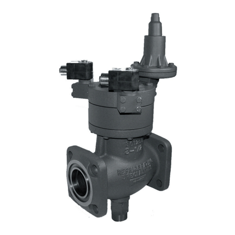
Mount only in horizontal pipe line with solenoid coil at the top; this valve
will work properly only in this position. In a liquid line the Solenoid Valve
should be near the expansion valve inlet. It is advisable to install the S4A
close coupled companion strainer ahead of the valve for protection against
dirt and chips.
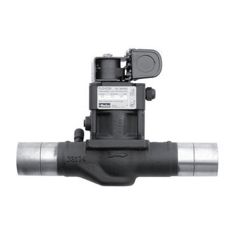
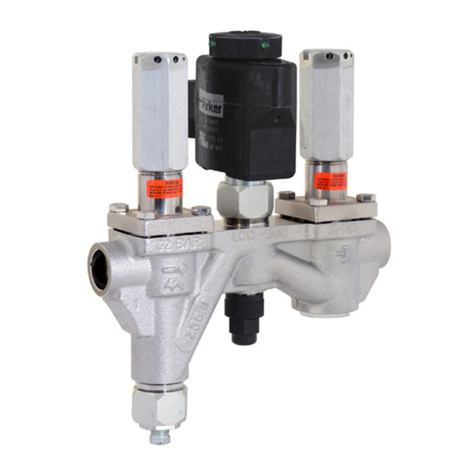
The S4A solenoid valve must be installed with the arrow on the valve
body in the direction of flow through the valve. If the valve is backwards,
the flow will not be stopped when the valve is electrically de-energized.
Like all Solenoid Valves, the S4A can stop flow only in the direction from
normal inlet to normal outlet (as shown by the arrow on the body).If reversal
of pressure occurs in the system so the outlet pressure exceeds the inlet
pressure the piston will be blown away from its seat and reverse flow will
occur. If a system has this type of pressure reversal (as encountered
during hot gas defrost with liquid recirculation systems), a check valve
such as Refrigerating Specialties Division Type CK4A in series with the
solenoid valve will prevent flow reversal. (CK4A must be installed
downstream to avoid trapping liquid.)
Electrical
The Refrigerating Specialties Division molded water resistant Class “B”
solenoid coil is designed for long life and powerful opening force. The
standard coil housing meets NEMA 3R and 4 requirements. This sealed
construction can withstand direct contact with moisture and ice. The coil
housing far exceeds the requirements of NEMA Standard ICS, 1-110.57
salt spray test for rust resistance.
By definition, Class “B” coil construction will permit coil temperatures, as
measured by resistance method, as high as 130°C (266°F). Final coil
temperatures are a function of both fluid and ambient temperatures.The
higher fluid temperatures require lower ambient temperatures so the
maximum coil temperature is not exceeded. Conversely, low fluid
temperatures permit higher ambient temperatures.
The molded Class “B” coil is available from stock with most standard
voltages. However, coils are available for other voltages and frequencies,
as well as for direct current. Coils are also available as transformer type
with a 6 volt secondary winding for use with the Refrigerating Specialties
Division Pilot Light Assembly (see current copy of Bulletin 60-10, “Pilot
Light Assembly and Solenoid Transformer Coil”).
The solenoid coil must be connected to electrical lines with volts and
Hertz same as stamped on coil.The supply circuits must be properly sized
to give adequate voltage at the coil leads even when other electrical
equipment is operating. The coil is designed to operate with line voltage
from 85% to 110% of rated coil voltage. Operating with a line voltage
above or below these limits may result in coil burnout.Also, operating with
line voltage below the limit will definitely result in lowering the valve opening
pressure differential. Power consumption during normal operation will be
33 watts or less.
Inrush and running current is listed below: Inrush Running Fuse
Standard Current Current Size
Volts/Hertz (Amps) (Amps) (Amps)
120/60 (Blue leads) 1.18 0.46 1
208/60 (Blue & Red leads) 0.63 0.25 1
240/60 (Red leads) 0.60 0.23 1
440/60 (Yellow & Red leads) 0.39 0.13 1
115/50 (Yellow & Blue leads) 1.22 0.21 1
230/50 (Yellow leads) 0.65 0.261
Other (Contact Factory)
On transformer coil the 6 volt leads are always black.
Service Pointers
The S4A Solenoid Valve and Strainer are easily removable for cleaning or
repairing. To remove valve and strainer, first manually open the valve and
pump out the refrigerant in the section of the line sealed off.Then unscrew
the flange bolts and spread the flanges slightly apart.
1. Failure to Open: (a) Coil is of incorrectly high voltage. See “Electrical.”
Check voltage printed on the coil. (b) Line voltage is abnormally low. See
“Electrical.” Check line voltage at coil leads with a voltmeter. (c) Failure to
electrically energize. Check control circuit. (d) Pressure difference across
valve is too high.The S4A will open against a maximum pressure difference
across the valve of 21 bar (300 psig). (e) Solenoid Coil is burned out. See
“Electrical,” and replace with proper coil. (f) Plunger/Needle Assembly is
sticking. To disassemble the S4A for inspection of internal parts (after
pumping out the system as required): disconnect power source to #4
Solenoid Coil, remove #7 Tube Assembly, lift out #9 Plunger Assembly,
then remove #11 Adapter Assembly. Remove every trace of dirt from the
piston and cylinder using fine emery cloth to remove burrs if necessary.
Thoroughly clean all parts and reassemble using a light film of refrigeration
oil on the Piston.
2.Failure to Close:(a) Electrical control circuit is not opening properly.
Check wiring and controls.(b)There are chips or dirt on the Pilot Seat
or the Main Valve Seat, preventing proper seating. Disassemble and
clean Valve as outlined in (1f) above. (c) Main Valve Seat, Pilot Seat,
or Valve Needle may be worn or damaged and therefore leaking.
Disassemble and cleanValve as outlined in (1f) above.If any of these
parts need replacing, it is advisable to replace using the proper
replacement kit. (d) #13 Piston is sticking. See (1f) above. (e) #16C
Manual Opening Stem is turned all or partly out holding #16A
Modulating Plug Assembly open and permitting flow through the valve.
(f) #5 Coil Housing Screw (made of non-magnetic stainless steel) has
been replaced with a screw made of magnetic material and residual
magnetismis holding #9 Plunger Needle Assemblyin the open position.
Consequently, the Main Valve is not closing. Replace with screw of
correct material.
3. Leakage Through Valve: See (2) above.
4. Overheating: The Solenoid Coil is designed to operate hot and is
constructed of high temperature materials accordingly. Unless
troubled with actual Coil burnouts, high coil temperature should be
ignored. Persistent burnouts indicate improper line or coil voltage.
See (1e) above.
Warranty
All Refrigerating Specialties Products are warranted against defect in
workmanship and materials for a period of one year from date of shipment
from factory. This warranty is in force only when products are properly
installed, field assembled, maintained and operated in use and service as
specifically stated in Refrigerating Specialties Catalogs or Bulletins for
normal refrigeration applications, unless otherwise approved in writing by
Refrigerating Specialties Division. Defective products, or parts thereof,
returned to the factory with transportation charges prepaid and found to
be defective by factory inspection will be replaced or repaired at
Refrigerating Specialties option, free of charge, F.O.B. factory. Warranty
does not cover products which have been altered or repaired in the field,
damaged in transit, or have suffered accidents, misuse, or abuse.Products
disabled by dirt or other foreign substances will not be considered defective.
THE EXPRESS WARRANTY SET FORTH ABOVE CONSTITUTES THE
ONLY WARRANTY APPLICABLE TO REFRIGERATING SPECIALTIES
PRODUCTS, AND IS IN LIEU OF ALL OTHER WARRANTIES.EXPRESS
OR IMPLIED, WRITTEN OR ORAL, INCLUDING ANY WARRANTY OF
MERCHANTABILITY, OR FITNESS FOR A PARTICULAR PURPOSE.No
employee,agent, dealer or other person is authorized to giveany warranties
on behalf of Refrigerating Specialties, nor to assume, for Refrigerating
Specialties, any other liability in connection with any of its products.
Safe Operation (see also Bulletin RSB)
People doing any work on a refrigeration system must be qualified and
completely familiar with the system and the Refrigerating Specialties
Division valves involved, or all other precautions will be meaningless.This
includes reading and understanding pertinent Refrigerating Specialties
Division Product Bulletins, and Safety Bulletin RSBCV prior to installation
or servicing work.
Where cold refrigerant liquid lines are used, it is necessary that certain
precautions be taken to avoid damage which could result from liquid
expansion.Temperature increase in a piping section full of solid liquid will
cause high pressure due to the expanding liquid which can possibly rupture
a gasket, pipe or valve. All hand valves isolating such sections should be
marked, warning against accidental closing, and must not be closed until
the liquid is removed. Check valves must never be installed upstream of
solenoid valves, or regulators with electric shut-off, nor should hand valves
upstream of solenoid valves or downstream of check valves be closed
until the liquid has been removed. It is advisable to properly install relief
devices in any section where liquid expansion could take place.
Avoid all piping or control arrangements which might produce thermal or
pressure shock.
For the protection of people and products, all refrigerant must be removed
from the section to be worked on before a valve, strainer, or other device
is opened or removed.
Flanges with ODS connections are not suitable for ammonia service.
