Grafik Eye GRX-PWM Owner's manual

Switched Hot Current
100-277 V
Source/Load Type
Fluorescent:
Lutron Eco-10TM
(TVE Series)
Electronic Capacitive Non-Dim
Other Manufacturer’s 12 V
PWM Ballasts
(12 V PWM source only)
Incandescent
Low-Voltage
Metal Halide
Neon/Cold Cathode
16 A
16 A
16 A
16 A
16 A
16 A
16 A
Motors 1/4 HP @ 100-120 V
1/2 HP @ 200-277 V
Four Mounting Holes
Diameter - 0.25 in. (6mm)
Four Screws
Secure Cover
6.10 in.
(155 mm)
3.30 in.
(84 mm)
12.50 in.
(318 mm)
11.75 in.
(298 mm)
4.0 in.
(102 mm)
COOPERSBURG, PA 18036 U.S.A .
G 8 BR
144-317 GRX-TVI 1-9
12 V PWM INTERFACE CONTROL
Control Input:
100-240 V 50/60Hz
Switched Output: 100-240
GRX-PWM
Incandescent 16A
Fluorescent 16A
Low-voltage 16A
Metal Halide 16A
Neon/Cold Cathode 16A
Motor 1/4 HP@120V
1/2 HP@277V
®
Control
GRX-PWM Input Rating
IH20.02A
IDH 20.1A
Load T ype Switched
Ratings
0-12V Output Rating
Max. 0.4A Class2
Installation and Operation Instructions
Please Read before Installing
Occupant Copy
GRX-PWM Control Interface
GRX-PWM-JA Control Interface
Phase Control to PWM
Description
The GRX-PWM provides 12 V Pulse Width Modulated (PWM)
control and ballast switching capabilities in one enclosure. With
the GRX-PWM, a
GRAFIK Eye
3000 Series Control Unit* can
control PWM ballasts powered by 100-277 V and provide
switching relays that can handle the in-rush current for a full
circuit of ballasts. The GRX-PWM can also be used to switch any
of the load types listed below.
*GRX-PWM will also work with Lutron GP or LP panel outputs.
Note: When using a Control Unit, a GRX-PWM is required for each
12 V PWM fluorescent zone. (A 3-zone Control Unit with two
fluorescent zones and one incandescent zone is shown as an
example.)
Mounting
Find a suitable location for mounting.
•Decide on the proper location for the GRX-PWM (NEMA Type 1
enclosure, indoor use only). See System Wiring Layout below.
•The environment where the GRX-PWM is placed must have an
ambient temperature range of 32-104°F (0-40°C).
•Mount the enclosure vertically on a wall (screws not provided).
See Mounting Diagram below.
•Mounting method must be able to support weight and forces
applied during installation.
•Internal relays will click while in operation; mount where
audible noise is acceptable.
System Wiring Layout
Mounting Diagram
®
R
Product Specifications
4 mounting holes
Diameter: 0.25 in. (6 mm) 4 screws secure cover
12.5 in.
(318 mm)
3.30 in.
(84 mm)
3.35 in.
(85 mm)
1.3 in.
(34 mm)
1.6 in.
(41 mm)
6.10 in.
(155 mm)
LUTRON LUTRON
LUTRON
PWM Control Fluorescent Zone/Load 1
PWM Ballast
Power from
Distribution
Panel
GRX-
PWM
GRX-
PWM
Ballast
Switched Fluorescent Zone/Load 2
Incandescent Zone/Load 3
Control Unit PELV (Class 2: USA) Accessory Controls
PWM Ballast
COOPERSBURG, PA 18036 U.S.A .
G 8 BR
144-317 GRX-TVI 1-9
12 V PWM INTERFACE CONTROL
Control Input:
100-240 V 50/60Hz
Switched Output: 100-240
GRX-PWM
Incandescent 16A
Fluorescent 16A
Low-voltage 16A
Metal Halide 16A
Neon/Cold Cathode 16A
Motor 1/4 HP@120V
1/2 HP@277V
®
Control
GRX-PWM Input Rating
IH20.02A
IDH 20.1A
Load T ype Switched
Ratings
0-12V OutputRating
Max. 0.4A Class 2
4.0 in.
(102 mm)
11.75 in.
(298 mm) WALL
FEATURES....................Provides a PELV (Class 2: USA) isolated 12 V 1 kHz
PWM output signal that conforms to IEC60929 and
JIS C8120-2.
Accepts a constant-gate drive fluorescent signal
INPUT VOLTAGE RATING 100/120 V , 50/60 Hz
SWITCHED VOLTAGE RATING 100-277 V , 50/60 Hz
H2 TERMINAL INPUT RATING 200 mA max
DH2 TERMINAL INPUT RATING 100 mA
12 V PWM OUTPUT RATING 400 mA - sources current only
TERMINALS Two #12-20 AWG (0.5-2.5 mm2) conductors per terminal.
MOUNTING NEMA Type 1 enclosure, indoor use only.
ENVIRONMENTAL 32-104°F (0-40°C).
WEIGHT 4.25 lb. (2 kg)
100-277 V 50/60 Hz

2
R
100-277 V Control Interface
Important Installation Information
•Install in accordance with all national and local electrical codes.
•Check for short-circuited loads during new installations before wiring the GRX-PWM.
Caution: Multiple feeds may enter this enclosure. Locate and lock each feed circuit breaker/MCB in the OFF
position before wiring the Interface.
•Proper short-circuit and overload protection must be provided at the distribution panel. You can use up to a 20 A
maximum circuit breaker/MCB or equivalent (tripping curve C according to IEC 898/EN60898 is recommended) with
adequate short-circuit breaking capacity for your installation.
•Terminal blocks are rated for two #12-20 AWG (0.5-2.5 mm2) wires per terminal.
•Strip 3/8 in. (10 mm) of insulation from wires.
•Wiring Diagram A shows a GRX-PWM wired from one distribution panel. If the
power requirement of the complete system is less than an MCB/circuit breaker
rating, one feed can be jumpered inside the enclosure (as shown).
•Wiring Diagram B shows a GRX-PWM wired from two separate distribution panels that may be different phases or
voltages.
•Use the internal terminal block label to see where to land wires.
— The label shows two separate Hot terminals (H1& H2).
H1is the Hot feed to power the lighting load.
H2is the Hot feed that powers internal circuitry of the GRX-PWM.
H2has a 100/120 V connection. Do not use the unlabeled
terminal.
Note 1: Not all terminal blocks receive a connection.
Note 2: The power feed to the Control Unit and H2of the
GRX-PWM must be the same phase!
PELV (Class 2: USA), 12 V PWM wiring from a
ballast to the GRX-PWM must be separated from the
power wiring. Enter the PELV (Class 2: USA) wires
through the knockout adjacent to the 12 V PWM terminal blocks. The Nomex®barrier ensures
separation and is flexible to allow access to the terminals. The barrier must be in place when installation
is complete.
GRX-PWM Internal Terminal Block Label Definitions
H2100/120 V Power input for GRX-PWM control (line voltage
must be
100/120 V only)
N2Neutral for GRX-PWM control
DH2
GRAFIK Eye
3000 Series Control Unit Lighting Zone connection
(Phase Control Input to GRX-PWM)
H1Power input for lighting load (switched voltage can be 100-277 V )
N1Neutral for lighting load (2 terminals provided and internally tied together — one for input neutral,
and one for load neutral)
SH1Switched output to power lighting load
+ - PWM control signal terminals
100/120 V
line voltage
Do not use
Input from distribution
panel
100-277 V
3/8”
(10 mm)
H2N2DH2
12 V
PWM
H1N1N1SH1

100-
127V
220-
240V
N2
DL2/DH2
L1/H1
N1N1SL1/SH1 + –
Max0.3A
0-10V
ControlInput s LoadSwitched
L2/H2 100-
277V
EAR TH/GROUND
CONNECTIONS
L2/H2 100-120V
N2
DL2/D H 2
L1/H 1
N1
N1
SL1/SH 1
0-10 Volt
NEUTRAL
L2/H 2220-240V
N
LUTRO N
3
Wiring Diagram A: 100/120 V GRX-PWM: 1 Distribution Panel
Earth/Ground
GRX-3000
Distribution
Panel
PWM Ballast
PWM Ballast
Dimmed Hot
Neutral
Neutral
Neutral
Hot
Switched Hot
Hot
Use 20 A maximum
circuit breaker/MCB
To additional ballasts (50 max.)
GRX-PWM
PWM Control Signal Wires: DO NOT
CONNECT TO LINE VOLTAGE. Lutron is not
liable for damage due to miswiring.
Earth/Ground
Earth/Ground
Wiring Diagram B: 100-277 V GRX-PWM: 2 Distribution Panels
R
Earth/Ground
connections
100-
127V
220-
240V
N2
DL2/DH2
L1/H1
N
1
N
1
SL1/SH1 + –
Max0.3A
0-10V
ControlInputs LoadSwitched
L2/H2 100-
277V
EAR TH/GROUND
CONNECTIONS
L2/H2 100-120V
N2
DL2/D H 2
L1/H 1
N1
N1
SL1/SH 1
0-10 Volt
NEUTRA L
L2/H 2220-240V
N
LUTRO N
N
Earth/Ground
Distribution
Panel
PWM Ballast
PWM Ballast
Dimmed Hot
Neutral
Neutral
Neutral
Hot
Switched Hot
Hot
Use 20 A maximum
circuit breaker/MCB
To additional ballasts (50 max.)
PWM Control Signal Wires - DO NOT
CONNECT TO LINE VOLTAGE. Lutron is not
liable for damage due to miswiring.
Earth/Ground
Earth/Ground
Earth/Ground
connections
Earth/Ground
Distribution
Panel
Neutral
Hot
GRX-3000
GRX-PWM
Line Voltage:
100-277 V
Line Voltage:
100/120 V
100/120 V
100/120 V
100-277 V
H2is the Hot feed
that powers the internal circuitry
of the GRX-PWM. Use H2
100/120 V only if your line
voltage is 100/120 V .
H1is the Switched Hot feed to the
load. Use a separate lead to H1if
your line voltage is 100-277 V .
H2is the Hot feed
that powers the internal circuitry
of the GRX-PWM. Use H2
100/120 V only if your line
voltage is 100/120 V .
-
+
SH1
N1
-
+
SH1
N1
H2N2 DH2
12 V
PWM
H1N1N1SH1
H2N2 DH2
12 V
PWM
H1N1N1SH1
-
+
SH1
N1
-
+
SH1
N1

Operation
After wiring is complete, supply power to the GRX-PWM to check for proper operation.
•With the cover removed, an LED will provide visual feedback about the operation of the system.
•When power is first applied, the LED will turn on for 8 seconds to indicate start-up mode and then start to flash in one of two ways
to indicate the status of the system:
1. Standard Operation
•The LED will flash at a rate of twice per second to signify proper communication between the Control Unit and the Interface.
2. Incorrect Operation - No Active Input
•The LED will repeatedly turn on for 1 second, then off for 1 second, to indicate that there is not an active phase control input to
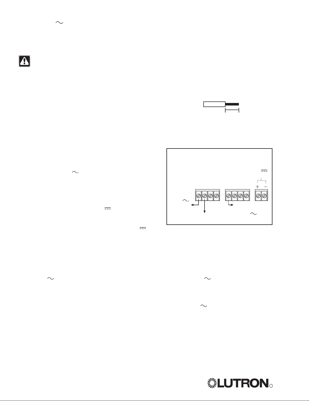
the GRX-PWM. Make sure that the phase control dimmer is ON and connected to the GRX-PWM at the terminal block marked
DH2. Check that the corresponding zone for the DH2terminal is ON and the light level is not set at the minimum output.
•When the LED indicates proper input of a phase control signal, then the output can be checked by looking at the load and
checking operation from the Control Unit.
•For non-dimming ballasts, select non-dim load type on the
GRAFIK Eye
Control Unit and do not connect ballasts to PWM’s + and -
terminals.
Make sure that the Control Unit is set for Fluorescent Load Type. (Refer to
GRAFIK Eye
3000 Series Installer's Guide.) If the
load type is not set correctly, proper dimming will not occur.
Solution
Verify that LED pulses twice per second. If not, check wiring from phase control unit to the
Interface.
Make sure that the
GRAFIK Eye
3000 Series Control Unit is ON.
Check for proper polarity of PWM signals at terminal blocks. Does it match what is at every
ballast? A miswire at any ballast will cause all ballasts to go to the low end.
GRAFIK Eye
3000 Series Control Unit is not configured for fluorescent load type.
Check that the SH1connection goes to the ballasts.
Check that the DH2connection is actually wired to a phase control input.
Check that load is connected to SH terminal.
Check that the DH2connection is actually wired to a phase control input.
Check that power is applied to the Interface.
Symptom
PWM Ballast does not dim or control
unit to the Interface.
Light does not switch on
Light does not switch off
LED is not illuminated
Possible Cause
Miswire
Power is OFF
Miswire
Incorrect control setup
Miswire
Miswire
Miswire
Miswire
No power input
Troubleshooting
Lutron Electronics Co., Inc.
Made and printed in U.S.A. 2/06
P/N 031-267 Rev. A
R
LIMITED WARRANTY
Lutron will, at its option, repair or replace any unit that is
defective in materials or manufacture within one year after
purchase. For warranty service, return unit to place of purchase
or mail to Lutron at 7200 Suter Rd., Coopersburg, PA 18036-
1299, postage pre-paid.
This warranty is in lieu of all other express warranties, and the
implied warranty of merchantability is limited to one year from
purchase. This warranty does not cover the cost of installation,
removal or reinstallation, or damage resulting from misuse,
abuse, or improper or incorrect repair, or damage from improper
wiring or installation. This warranty does not cover incidental or
consequential damages. Lutron’s liability on any claim for
damages arising out of or in connection with the manufacture,
sale, installation, delivery, or use of the unit shall never exceed
the purchase price of the unit.
This warranty gives you specific legal rights, and you may also
have other rights which vary from state to state. Some states do
not allow limitations on how long an implied warranty lasts, so
the above limitation may not apply to you. Some states do not
allow the exclusion or limitation of incidental or consequential
damages, so the above limitation or exclusion may not apply to
you.
This product may be covered by one or more of the following
U.S. Patents: 4,797,599; 5,309,068; 5,633,540; and
corresponding foreign patents.
Nomex
is a registered trademark of E.I. Du Pont de Nemours and
Company.
Lutron, the sunburst logo, and GRAFIK Eye are registered
trademarks; Eco-10 is a trademark of Lutron Electronics Co., Inc.
© 2006 Lutron Electronics Co., Inc.
Internet: www.lutron.com
E-mail: [email protected]
WORLD HEADQUARTERS
Lutron Electronics Co., Inc.
7200 Suter Road, Coopersburg, PA 18036
TEL +1-610-282-3800
FAX +1-610-282-1243
EUROPEAN HEADQUARTERS
Lutron EA Ltd.
6 Sovereign Close, Wapping, London, E1W
3JF United Kingdom
TEL +44-207-702-0657
FAX +44-207-480-6899
FREEPHONE (UK) 0800-282-107
Technical support +44-(0)20-7680-4481
WORLDWIDE OFFICES
Brazil
Lutron BZ do Brasil Ltda.
AV, Brasil, 239, Jardim America,
Sao Paulo-SP, CEP01431-000, Brasil
TEL +55 11 3885-5152
France
Lutron LTC, S.A.R.L.
90 rue de Villiers, 92300 Levallois-Perret
France
TEL +33-(0) 1-41-05-42-80
FAX +33-(0) 1-41-05-01-80
FREEPHONE 0800-90-12-18
Germany
Lutron Electronics GmbH, Landsberger
Allee 201, 13055 Berlin, Germany
TEL +49-309-710-4590
FAX +49-309-710-4591
FREEPHONE 00800-5887 6635
Italy
Lutron LDV, S.r.l.
FREEPHONE 800-979-208
Spain, Madrid
Lutron CC, S.R.L.
Calle Orense, 85, 28020 Madrid, Spain
TEL +34-91-567-84 79
FAX +34-91-567-84 78
FREEPHONE 0900-948-944
Spain, Barcelona
Lutron CC, S.R.L.
Gran Via del Carlos III, 84, planta 3a,
08028,
Barcelona, Spain
TEL +34-93-496-57 42
FAX +34-93-496-57 01
FREEPHONE 0900-948-944
China, Beijing
Lutron GL Ltd.
5th Floor, China Life Tower, No. 16 Chaowai
Street, Chaoyang District, Beijing 100020
China
TEL +86-10-5877-1817
FAX +86-10-5877-1816
China, Shanghai
Lutron GL Ltd.
Suite 07, 39th Floor, Plaza 66,
1266 Nan Jing West Road, Shanghai,
200040 China
TEL +86-21-6288-1473
FAX +86-21-6288-1751
China, Guangzhou
Lutron GL Ltd. Guangzhou Representative
Office
Plaza Business and Conference Centre
(Guangzhou)
Suite A09, 23/F Tower A, Center Plaza,
161 LinHeXiLu, Tianhe District, Guangzhou
510620 China
TEL +86-20-2885-8266
FAX +86-20-2885-8366
Hong Kong
Lutron GL Ltd.
Room 2808, 28/F, 248 Queen's Road East,
Wanchai, Hong Kong
TEL +852-2104-7733
FAX +852-2104-7633
Japan
Lutron Asuka Co. Ltd.
No. 16 Kowa Building, 4F, 1-9-20, Akasaka,
Minato-ku, Tokyo 107-0052 Japan
TEL +81-3-5575-8411
FAX +81-3-5575-8420
Singapore
Lutron GL Ltd.
6A Upper Cross Street, Singapore 058326
TEL +65-6220-4666
FAX +65-6220-4333
Asia Technical Hotlines
Northern China: 10-800-712-1536
Southern China: 10-800-120-1536
Hong Kong: 800-901-849
Singapore: 800-120-4491
Taiwan: 00-801-137-737
Thailand: 001-800-120-665853
This manual suits for next models
1
Other Grafik Eye Recording Equipment manuals