Grafisk Maskinfabrik DC330 Quick start guide

Page: 2/22 Revision 1.01 Date: 2016-05-27
Revision 1.00 –HH
Revision 1.01 –HH

Page: 3/22 Revision 1.01 Date: 2016-05-27
Table of Contents
Checklist.......................................................................................................................................................... 4
1. General Information........................................................................................................................... 4
2. Installation Steps for Upgrading DC330 with theSpot Varnish option...................................... 5
3. Galil Software Update for Spot Varnish........................................................................................14
Appendix I.....................................................................................................................................................21

Page: 4/22 Revision 1.01 Date: 2016-05-27
Checklist
Before starting the upgrade process, make sure that all conditions in the following part list are fulfilled:
1. Extra servo driver, programmed for spot varnish.
2. Servo motor and wiring cables.
3. Correct program for the Galil software.
4. Spot home inductive sensor including bracket.
5. Side adjustment encoder.
6. Side adjustment for varnish roller.
7. Optional: Schneider programming cable –just in case.
1. GeneralInformation
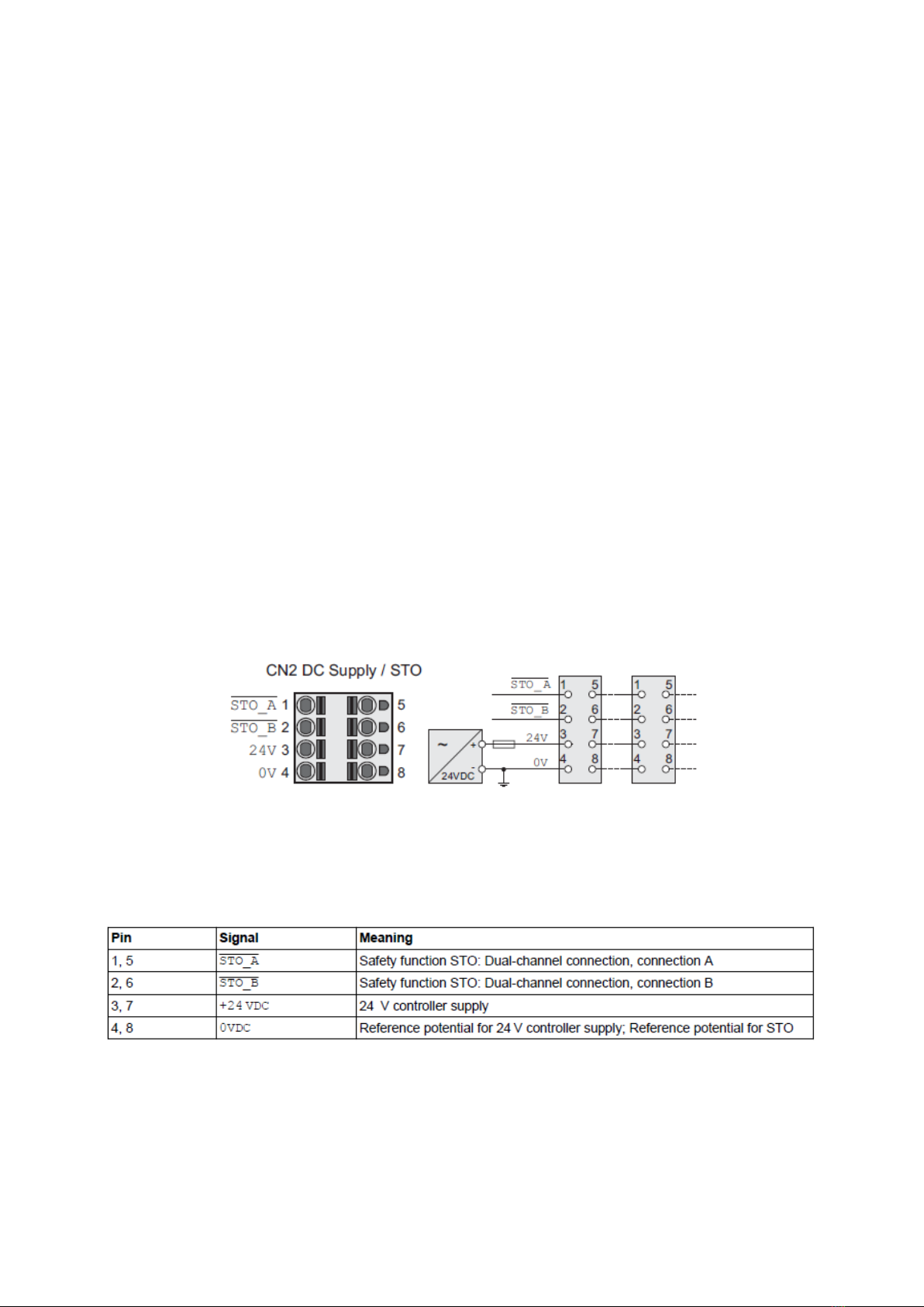
Awiringdiagram ofthemainconnectorsontheservos,thatwillbeusedinthismanualare showninFigure
1 and Figure 2. Also notice that the table here below refers onlyto the wiring diagram in Figure 1.
Figure 1: Wiring diagram controller supply (on top of servo drive).

Page: 5/22 Revision 1.01 Date: 2016-05-27
Figure 2: Wiring diagram, digital inputs/outputs (in front of servo drive).
Notice that function input DI0 refers to “Enable”, and DI1 to “Fault reset”
(See
Appendix Ifor more detail).
2. InstallationStepsforUpgradingDC330withtheSpotVarnishoption
Figure 3 and Figure 4 show the servo wiring setup before upgrade, along with the placement of the new
servo for the spot varnish nip (SRV.F).
Step 1:
Mount servo F in series with the servos, and in a alphabetical order, as shown in Figure 3
(SRV.F, marked with a red square).

Page: 6/22 Revision 1.01 Date: 2016-05-27
Figure 3: Servo wiring (CN2) setup before upgrade and servo F (SRV.F) for spot varnish.
Figure 4: Servo wiring (CN6) setup before upgrade and servo F (SRV.F) for spot varnish.
Step 2:
Notice that the followingnumbered steps relates to corresponding steps marked in Figure 5.
1. Disconnect the Red (24V, pin 7) and Black (0V, pin 8) wires on servo SRV.D.
2. Disconnect the CN2 plug from SRV.E and connect the plugto SRV.F.
3. Disconnect the CN6 plug from SRV.E and connect the plugto SRV.F

Page: 7/22 Revision 1.01 Date: 2016-05-27
Figure 5: Steps for moving plugs CN2 and CN6 from SRV.E to SRV.F.
Step 3:
Notice that the following numbered steps relates to corresponding steps marked in
Figure 6.
1. Connect the white and brown wires to STO A (pin 5)and STO B (pin 6) on
SRV.D, and STO A (pin 5) and STO B (pin 6) on SRV.E, respectively.
2. Connect Red (24V) and Black (0V) wires in series for servos SRV.D and
SRV.E.
Note: 24V and 0V connectors on SRV.D are pins 7 and 8, and pins 3 and 4 on
SRV.E, respectively.
3. Connect Red (24V) and Black (0V) wires in series from servo SRV.F to
SRV.E.

Page: 8/22 Revision 1.01 Date: 2016-05-27
Figure 6: CN2 wiring setup for upgrade.
Note: Remember the wiring diagram in Figure 1 and Figure 2 for pin references for plugs
CN2 and CN6.
Step 4:
Notice that the followingnumbered steps relates to corresponding steps marked in Figure 7
and Figure 8.
1. Start bychecking if the wire connections for plug CN6 on SRV.F is connected as
can be seen in Figure 7.
2. Connect the wires for the CN6 plug on SRV.E as shown in Figure 7. If connected
from factory, check connections.
3. On the Galil board, move the 15 pin cable for E-axis to the F-axis (See Figure 8), to
make the same changes for the Galil board as for the servos.

Page: 9/22 Revision 1.01 Date: 2016-05-27
Figure 7: CN6 wiring setup after upgrade.

Page: 10/22 Revision 1.01 Date: 2016-05-27
Figure 8: 15 pin cable wiring setup on the Galil board.
Figure 9: Wiring for safety board (Cable E/F fromSpot Varnish Servo (SRV.F)).

Page: 13/22 Revision 1.01 Date: 2016-05-27
Figure 12: Connection locations for encoder, markreader and home sensor.
Figure 13: Wiring diagramof the X5 board.
Step 7:
Wiring connections to the X5 board, and from X5 board to the Galil board is shown in
Figure 12,Figure 13 andFigure 14.
Notice that in Figure 13 the optional plugins for the spot varnish is marked with blue dotted
squares.

Page: 14/22 Revision 1.01 Date: 2016-05-27
Figure 14: Connections from X5 board to Galil board.
3. Galil SoftwareUpdateforSpotVarnish
1) Install latest version of the GalilSuite (http://www.galilmc.com/downloads/software/galilsuite)
2) Obtain matching DC330_SINGLE_DIECUT_SINGLESPOT_vxxx.dmc program.
3) Set your PC’s wired Ethernet adapter:
a) Set IP address to 192.168.2.254
b) Set subnet mask address to 255.255.255.0

Page: 15/22 Revision 1.01 Date: 2016-05-27
4) Connect your PC via Ethernet cable to the Galil Ethernet port (or in network switch).
5) Start GalilSuite and click connect.
6) Select the Ethernet device from the list and click Connect.
7) From the GalilSuite main window, Click Terminal.

Page: 16/22 Revision 1.01 Date: 2016-05-27
8) Upload the current program on the Galil and save on your local PC as a backup.
9) From the Terminal windows, Click the Download arrow.
10) Select the DC330_SINGLE_DIECUT_SINGLESPOT_vxxx.dmc file and click open.
11) After a successful download , type BP into the terminal and press Enter.
Note: Only capital letter can be used to execute Galil commands in the terminal window.
12) Reset the Galil controller bytyping RS in the terminal window and press Enter.

Page: 17/22 Revision 1.01 Date: 2016-05-27
4. GuidelinestoProgramSchneiderServoforSingleSpotfeature.
1. Start bydownloadingthe latest version of SoMove and libraries needed. The latest versions are:
a) Software: SoMove 2.4
b) Library: Lexium32DTMLibrary_V1.14.01.02
To check if the installation of the software and corresponding libraries where successful, check
the firmware versions in the startup window in SoMove (Marked in the red square in the figure
below).
2. Do a Factory Reset on the servo by following the steps here below:
a) Press ESC button on the servo.
b) Turn the (CN7) Modbus (commissioning interface) and press “ Conf “.
c) Rotate until you find “ .FCS- “ and press.
d) Rotate and select “ .rstF ”.
e) Press again and check if LED for Edit is turned on. Rotate and select “ Yes ”
f) Press ESC button until you are out of the setting mode.

Page: 18/22 Revision 1.01 Date: 2016-05-27
3. Press Open a Project and choose the correct file for the servo (bmh1003spot_F_ver1.psx).
4. Go to the Communication tab and press Edit Connection.
5. When the window below opens, press the Advanced Settings button in the tor right corner.

Page: 19/22 Revision 1.01 Date: 2016-05-27
6. Select the correct COM Port as shown in the figure below:
7. Press Scan Network to find the servo that you are connected to.

Page: 20/22 Revision 1.01 Date: 2016-05-27
8. Go to the Communication tab and press Connect to device.
9. Select Store to device and connect option.
10. After the configuration file has been stored to the device the window below should appear.
11. Reboot the machine.
Table of contents
Other Grafisk Maskinfabrik Media Converter manuals