Grafisk Maskinfabrik DC330mini User manual

GM · CONVERTING UNIT
2
Rev 1.6 03/03- 2017
EU Declaration of Conformity
We Manufacturer:
Grafisk Maskinfabrik A/S
Bregnerødvej 92
DK-3460 Birkerød
Denmark
Telephone: + 45 45 81 23 00
Fax: + 45 45 81 99 56
Herewith declare that the product
Equipment: Converter
Model number: DC330NANOV2
Serial number / production year: 115331 / 2016
Is in compliance with the relevant requirements in the following directives:
Machinery Directive 2006/42/EC
EMC Directive 2004/108/EC
Harmonized specifications applied:
EN 60204-1 Safety of machinery. Electrical equipment of machinery.
EN 13849 Safety of machinery -- Safety-related parts of control systems
EN 12100 Safety of machinery
Person authorised to compile and hold the technical documentation:
Bjarne Nielsen
Managing Director
Uffe Nielsen (Mr.)
Grafisk Maskinfabrik A/S
01-04-2016 - Birkerød __________Uffe Nielsen__________
Date Signature

GM · CONVERTING UNIT
3
EU Declaration of Conformity..................................................................................................................... 2
1. Safety instructions............................................................................................................................... 5
2. DC330mini/nano note......................................................................................................................... 6
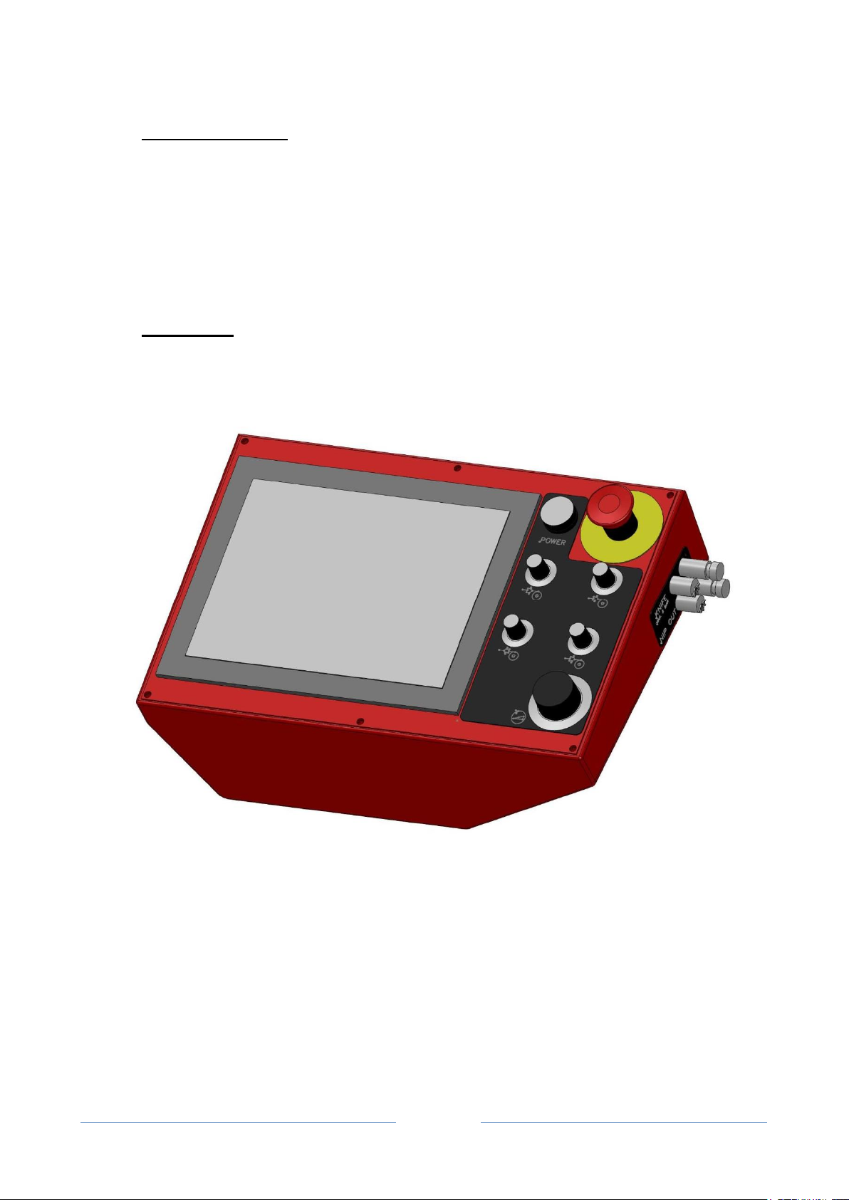
3. Control panel........................................................................................................................................ 6
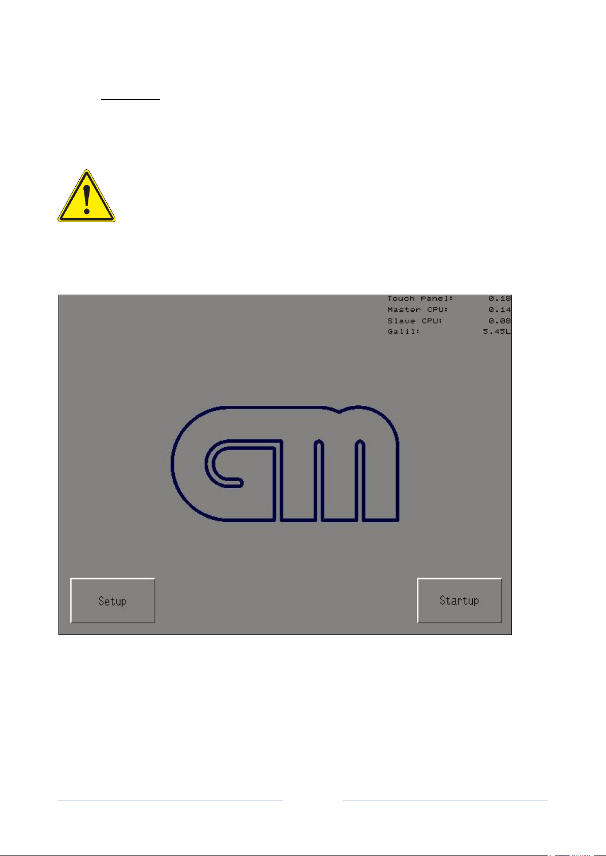
4. Touch panel.......................................................................................................................................... 7
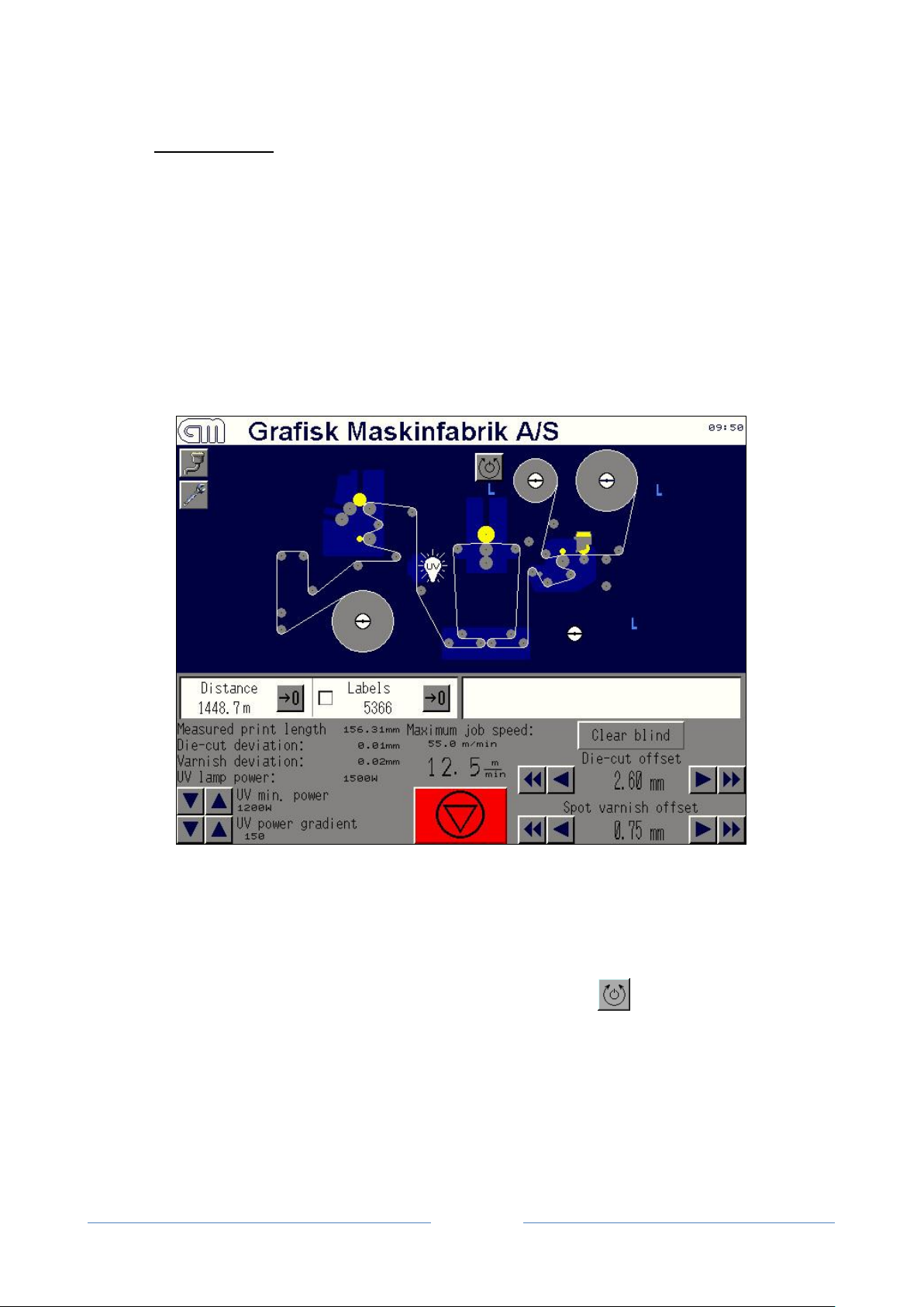
5. The main screen................................................................................................................................... 8
5.1. Web entry...........................................................................................................................................9
5.2. The varnish station.............................................................................................................................9
5.3. The spot varnish option .....................................................................................................................9
5.4. The laminating station (optional)......................................................................................................9
5.5. The UV lamp................................................................................................................................... 11
5.6. Safety instructions........................................................................................................................... 12
5.7. The die-cutting station.................................................................................................................... 13
5.8. Waste rewinder ............................................................................................................................... 14
5.9. V-knifes and Slitting knifes............................................................................................................ 14
5.10. Rewinding....................................................................................................................................... 15
6. Menu buttons.....................................................................................................................................16
6.1. Parameters....................................................................................................................................... 18
6.2. Die-cut parameters.......................................................................................................................... 20
6.3. Speed control................................................................................................................................... 23
6.4. Web tension and scale print adjustments....................................................................................... 24
7. Alarms and messages........................................................................................................................25
8. Language and units setup.................................................................................................................29
9. Special parameters............................................................................................................................30
10. Registration accuracy....................................................................................................................... 31
11. Markreader SUNX LX series..........................................................................................................32
12. Distortion and disprofactor.............................................................................................................33
13. Varnish station –prevent dripping.................................................................................................35
14. Dust problems with V-knifes & damages to anvil roller.............................................................36
15. Die cut station adjustment and alignment.....................................................................................36
16. Die cut bridge adjustment................................................................................................................ 37
17. General information for GM diecut station..................................................................................38
18. Varnish station................................................................................................................................... 41
18.1. Technical data ................................................................................................................................. 41
18.2. Anilox roller types .......................................................................................................................... 43
18.3. Mounting of the anilox roller ......................................................................................................... 44

GM · CONVERTING UNIT
4
18.4. Mounting of the ink roller............................................................................................................... 44
18.5. Mountingof side blades and doctor blade..................................................................................... 45
18.6. Filling of ink.................................................................................................................................... 46
18.7. Mounting of print cylinder ............................................................................................................. 46
18.8. Adjustment of impression............................................................................................................... 47
18.9. Cross register................................................................................................................................... 48
18.10. Triangle adjustment of the flexo unit (Coarse adjustment)........................................................... 49
18.11. Troubleshooting.............................................................................................................................. 50
19. Spot varnish guide.............................................................................................................................51
19.1. Step bystep guide........................................................................................................................... 52
19.2. Trouble shooting............................................................................................................................. 53
19.3. Pictures............................................................................................................................................ 53
19.4. The parameter screen...................................................................................................................... 54
19.5. The run screen................................................................................................................................. 55
19.6. Print scaling..................................................................................................................................... 56
20. Lamination (Tips and tricks)...........................................................................................................57
21. Operator Maintenance Chart..........................................................................................................58
22. Dimensions..........................................................................................................................................60
23. Spare parts and consumables..........................................................................................................61
24. Specification.......................................................................................................................................62
25. Cliché roller drawing........................................................................................................................63
26. Specification die cylinder.................................................................................................................. 64
27. Installation guide...............................................................................................................................65
28. Starting up the machine:.................................................................................................................. 66
29. Training:.............................................................................................................................................67
30. Notes....................................................................................................................................................69

GM · CONVERTING UNIT
5
1. Safetyinstructions
This chapter describes the safety guidelines that must be observed under all circumstances when
installing,commissioning, operating and maintaining the CONVERTING UNIT.
In this operating manual and on the unit, the followingsymbols will draw your attention especially to
hazards, risks and safety relevant information:
Indicates a potentially dangerous situation. Non-observance of the warning instructions
may lead to slight or medium personal injuryor damage to machine.
Indicates a potentiallydangerous situation. Removal of the cover behind this symbol
may lead to direct or in-direct exposure to high-voltage parts. This may lead to fatal
personal injury.
Indicates a potentiallydangerous situation. Possible trapping of hand between rotating
rollers. Removal of the cover behind this symbol may lead to slight or medium personal
injury.
Indicates a potentiallydangerous situation. Possible trappingof hand between rotating
rollers with sharp points (gears or other blunt parts). Removal of the cover behind this
symbol may lead to slight or medium personal injury.
Indicates general instructions, useful tips for application and recommendations for
working that do not have any influence on the safety and health of the personnel.

GM · CONVERTING UNIT
6
2. DC330mini/nanonote
This manual is for the DC330mini and the DC330nano
The DC330mini line is identical to the DC330 –only difference is that it is much more compact. The
DC330 nano does not have a flexo unit –it is lamination only.
The DC330mini & Nano can’t operate inline without a buffer module installed.
3. Controlpanel
The control panel is fitted with a touch panel, and on the right side, the POWER button, EmergencyStop
button, the four torque adjustment knobs, and the speed button .
The symbols indicate which spindle a torque control knob is related to.
On the side of the controlpanel, the manometer adjustment for knife and nip is placed.
To power up, first check that the main switch is turned ON, and the Emergency Stop buttons are released.
Press the POWER button. The touch panel will light up.

GM · CONVERTING UNIT
7
4. Touchpanel
The touch panel is the main control unit on the converting unit. All values regarding a job are entered
through the panel. It responds to light pressure onto the panel, thus responding when the user pushes a
virtual button or numeric value shown in the panel.
NOTE! Never hit the touch panel.
Do not press with sharp objects.
To clean the touch panel, soak a cloth inwater with a mild detergent, wring
the cloth tightly and wipe the panel. Never use strong detergents, paint
thinner, organic solvents or acid on the panel.
When the machine is turned on, the panel will light up, and after a few seconds the startup screen
emerges:
In the upper right corner, software versions are printed. This can be useful in maintenance situations.
To set language, units and clock, press 'Setup' (see appendix). To continue to the main screen, press
'Startup'.

GM · CONVERTING UNIT
8
5. Themainscreen
The majority of machine functions are operated on the main screen. A large graphic representation of the
machine is used for controlling:
•mandrel expansion
•spindle modes
•nip rollers
•varnish roller
•die-cut cylinder
•UV lamp
A number of buttons, checkboxes and readouts are placed on the lower part of the screen.
The converting unit is equipped with four spindles with different functions:
•Unwinder
•Waste rewinder
•Rewinder 1 (top)
•Rewinder 2 (bottom)
Each spindle will change mode when the attached rotation mode button is pressed. Two of the
spindles can run in both directions (the two main rewinders), and the rest can run in only one direction.
All spindles can be turned off.
When the center of a spindle is pressed, the air operated mandrel will expand (lock) or release.

GM · CONVERTING UNIT
9
5.1. Webentry
The web entry into the machine can be run in two different modes:
In Stand-alone mode, a roll is placed on the unwinder, labels out or labels in. The web must be fed
through the DCmimi buffer, which creates web tension, and controls the unwinder.
In Inline mode, the web is fed into the DCmini buffer and into the DCmini converting unit from another
machine, e.g. a print engine. Again, the web must be fed through the dancer, which now controls the web
speed together with the speed knob on the control panel.
5.2. Thevarnishstation
The varnish station contains the input nip roller and the varnish unit. Under normal operation, the input
nip must always be turned on, in order to create web tension. The nip roller is turned on and off by
pressing the small nip symbol in the lower part of the varnish station. Nips are coloured green when they
are off, and yellow when they are on.
The varnish roller can be engaged and released bypressing the roller symbol on the top of the varnish
station. It can also be turned on and off automaticallywhen the web starts and stop. If the feature
'Automatic varnish roller' is turned on, the varnish roller will be engaged when the web moves, and
released when the web stops.
5.3. Thespotvarnishoption
If the spot varnish option is installed, the varnish station can be used for full-rotation spot varnishing,
with varnish rollers from 10 to 19". In addition, a "slow run" feature is available, which is suitable for
varnish types which are not UV varnish. The spot varnish features are accessed in the Parameter menu.
5.4. Thelaminatingstation (optional)
The laminating station is a coldfoilstation.
It consists of two spindles, with the laminating nip and the UV lamp in between.
The laminate unwinder is above the UV lamp.
When laminating, the laminate nip roller will press the foil against the web. This nip roller can be
engaged only if the laminate unwinder is activated.

GM · CONVERTING UNIT
10
This is to prevent the rubber roller from accidentallybeing pressed into wet varnish or glue.
The pressure that the laminating nip applies onto the web can be adjusted with the air pressure regulator.
The pressure gauge will onlydisplay the pressure when the nip is engaged. If the regulator is turned all
the way to zero, the nip will not move when activated. A typical pressure setting is 1-2 bar.
The laminate unwinder will not rotate when the laminate nip is off. This is to prevent the laminate foil
from rotating freely through the laminating station.
For the DC330Mini, the following images illustrate the web path if running with an adhesive laminate
and the web path if running with supergloss laminate.
For the DC330Nano the image below illustrates the web path (in blue) for self adhesive laminate.
1) DC330Mini web path (in black) for selfadhesive
laminate
2) DC330Mini web path (in blue) for supergloss
laminate

GM · CONVERTING UNIT
11
5.5. TheUVlamp
The UV lamp is turned on and off be pressing the light bulb with the text 'UV'. When turned on, a few
seconds will pass before an attempt ismade to ignite the lamp. When the UV lamp ignites, it goes in to a
heatingsequence, which lasts about one minute. When the lamp is finally on, the lamp symbol turns
white.
If the lamp is hot when it is engaged, it will not turn on. The machine will let the lamp cool for a few
minutes, and will then try again automatically.
The UV lamp gets very hot, and proper cooling is necessary. Please check the cooling unit regularly.
When the lamp is lit, the cooling unit MUST be running.

GM · CONVERTING UNIT
12
5.6. Safetyinstructions
The following subsections describe any risks associated with handlingthe UV lamp and safety
precautions:
a. Ozone(O3)
The UV lamp generates Ozone which is normallyexhausted to the atmosphere. If a strong smell of
Ozone is detected check the ducting for any leakages.
Ensure that the installationis airtight and if anyozone filters are fitted, make sure they are changed
according to the maintenance schedules in the GEW installation manual.
b. Mercury (Hg)
Small quantities of Mercury are present in UV lamps, it is a toxic substance andmust be handled with
care. After handlingthe UV lamp make sure to ALWAYS wash your hands afterwards.
Broken lamps should be safelydisposed of:
NOTE: Heavy rubber gloves must be worn at all times
•Cover the mercury and broken glass with sand
•Collect the waste mixture with dustpan and brush, and transfer it to a cardboard box or other
expendable container.
•Always put the container in a thick plastic bag to protect any operator dealing with the waste.
Dispose of the bag in industrial waste containers or with local arrangements for disposal of
mercury.
c. Ultra-violet Radiation (UVR)
UVR is harmful to skin and eyes and is present in the ranges UV-A,UV-B. UV-C and UV-V. The GEW
UV dryer has shielding to prevent any accidental exposure of the operator to UVR, nevertheless it is still
ESSENTIAL to take care when operating the UV drying system.
•Wear protective clothing and eye protection if prolonged exposure is unavoidable and avoid
prolonged exposure of your hands in the area along the light shields
•Never look directlyinto the lamp head while the lamp is on
•Ensure that the shielding is kept in place at all times and is properly adjusted
d. High temperatures
High temperatures occur inside the UV dryer. Before attempting to remove or open any lamp head allow
the dryer to cool from full power for five minutes.

GM · CONVERTING UNIT
13
CAUTION: Never use flammable solvents near the UV dryer when the lamps are in
operation. If a fire should break out, only use fire extinguishers of the dry powder
type.
e. High voltages
UV lamps operate at high voltages (450V - 1400V) depending on the lamp type; additionalywhen
strikingthe lamps, ignitor circuitry will generate pulses in excess of 2kV. These high voltages present a
danger of electric shock or fire.
Other equipment mounted in the vicinityof the UV dryer should not interfere with the safe operation of
the system.
NOTE: When testing/troubleshooting the system, make sure that all cables are
intact and all safety interlocks in place.
5.7. Thedie-cutting station
This converting unit is equipped with a die-cutting station, which can run in several modes. Correct setup
is crucial to the operation of the die-cuttingstation. To enter the die-cut setup menu, press the button 'Die-
cut parameters'.
To raise and lower the die-cut cylinder, press the cylinder symbol. When the cylinder is up, the symbol is
green. When the cylinder is down (engaged), the symbol is yellow.
When the cylinder is activated in the touch panel, it will not be physically engaged if the die-cut station is
initializing, or if the die-cut feature has been turned off in the die-cut parameters menu.

GM · CONVERTING UNIT
14
To lower the die do the following:
1) Make sure the handles on the pressure bridge are lose
2) Turn on the air bypressing the cylinder symbol on the touch screen.
3) Turn the handles on the pressure bridge softly until theyare firm.
NOTE: Turning them down with excessive force will damage the die cylinder.
Once set, the die bridge can be operated by pressing up/down on the touch screen.
Remember to check that the die is always well oiled (oil pads) and there are no burn/track marks on the
sides.
5.8. Wasterewinder
The waste rewinder runs counter-clockwise only (glue inward). It is the only rewinder which can be
started and stopped while the machine is running. This is to make it easier to mount the waste grid.
5.9. V-knifesandSlittingknifes
After stripping, the web enters the output nip roller, which should normallybe on, to create web tension
through the die-cut station.. The output nip is turned on and off by pressing the nip symbol next to the
slitting knife.
The slitter knives come right after the output nip. They are either air operated , and are turned on and off
bypressing the knife symbol (see. Figure1)
Or with a handle activated manually. (Both sytems are optional)
The slitter knives (optional). They are operated manuallyby the handle at the station (see figure2).
Figure 1 - Airpressured V-knifes
Figure 2 –Manual handle

GM · CONVERTING UNIT
15
When produceing with slitting knives, it is very important to remember to mount the clamp (see figure3).
It will stabilize the two axles and ensure a clean cut . When not using slitting knifes, the handle must only
be moved when the clamp is removed. The clamp can NOT be mounted when slitting knifes are
disengaged.
The slitting blades are running synchronised with web at a speed around 5% higher than the web. This
speed increase improves the cutting quality. When the safety cover is opened, the motor is turned off and
the blades are safe to move. Do never tighten the blades too hard, theyjust get harder to remove.
NOTE! Never tryto open or close the slitter knife shafts with the knife clamp mounted
on the shafts. It will damage the balance in the shafts, and the knife clamp to lock the
shafts.
5.10. Rewinding
The two rewinders can run both ways, and can be individuallyturned off. As with all the other spindles,
the rotation mode is set with the rotation mode buttons, and the mandrel is engaged and released by
pressing the spindle.
The knife clamp
Figure 3 - Clamp mounted in slitting mode.

GM · CONVERTING UNIT
16
6. Menubuttons
Just below the machine drawing, you will find twowhite boxes. In the left box, two counters are placed:
A meter counter and a label counter. Each can be cleared bypressing the clear button [0]. Additionally,
the label counter can be turned on and off with the checkbox next to the counter. In the right box, info
messages, warnings and alarms will show up when the machine has something to report.
The 'Automatic stop at low unwinder diameter' feature makes the converting unit stop when the roll on
the unwinder spindle becomes smaller than a value entered in the Parameter menu.
When in inline mode this function is bypassed.
The 'Automatic stop at label preset' feature makes the converting unit stop when the label counter reaches
or exceeds the preset value entered in the Parameter menu.
'UV min. power' is the minimum power that the UV lamp will deliver when the web is moving. When
web speed increases, the output power will also be increased. The value is altered by pressing the two
arrow-buttons to the left.
'UV power gradient' is the rate at which the power increases when web speed increases. The actual unit is
[W/(m/min)], i.e. with a web speed of 20 m/min, and a gradient of 200, the output power will be 4000 W.
The absolute maximum output power is 5000 W.

GM · CONVERTING UNIT
17
The green button in the center bottom part of the screen is the start button. Press this to start the machine.
Pressing the 'Die-cut parameters' button will enter the die-cut setup menu.
Pressing the 'Parameter menu' button will open the parameter menu, which contains values and features
not directlyrelated to the die-cut station.
The 'Remote control window' button, or the button, opens a window with a remote controlling
feature for a digital press.
To stop the digital press, use the 'Remote Stop' button. The red lamp will light up briefly.
To make the remote control window disappear, press 'Close'.
To shut down the machine, press and hold 'Power off'. If the UV lamp is on, or has been on recently, the
machine will stayon (lamp off), and let the lamp cool before shutting down.

GM · CONVERTING UNIT
18
6.1. Parameters
The 'Automatic stop at low unwinder diameter' feature makes the converting unit stop when the roll on
the unwinder spindle becomes smaller than the value. The diameter range is 80 .. 200 mm (3.1 .. 7.9").
The 'Automatic stop at label preset' feature makes the converting unit stop when the label counter reaches
or exceeds the preset value. The maximum value is 999999.
Note: When running in-line with another machine, e.g. a print engine, the converting
unitdoes not stop when the preset value has been reached. This is to avoid web spilling
on the floor, or paper jam in the print engine.
The 'Automatic varnish roller' feature lifts the varnish roller when the web is not moving, and engages it
as soon as the web is moving again.
The 'Automatic laminate roller' feature lifts the laminate roller when the web is not moving, and engages
it as soon as the web is moving again.
The 'Nips and spindles off' feature may be useful when threading the machine. It lets the main motor run,
but turns off all spindles and nips.

GM · CONVERTING UNIT
19
If the spot varnish option is installedin the machine, it can be activated with the 'Use spot varnish'
checkbox. In addition, theexact size of the spot varnish cylinder must be keyed in, either in "teeth", or in
mm (or inches). The two radio buttons select which unit is used. If the cylinder is a regular cylinder,
divisible in teeth, use the 'Spot varnish cylinder teeth'. The range is 80 .. 152 z.
The cylinder could also be a little bit larger than the exact z value (up to 1 z larger in circumference). In
this case, use the 'Spot varnish cylinder size'. The range is 254.0 .. 482.6 mm (10.000 .. 19.000").
If the 'Automatic slow run' feature is on, the varnish roller will lift from the web, and turn slowly, in order
to keep the varnish in motion, when the web is not moving. However, all safety covers on the varnish
station must be closed. Otherwise the varnish rollers will stop.
The 'Rewinder 1 high torque' and 'Rewinder 2 high torque' options select the torque range for the two
rewind spindles. High range (box checked) is normallyused for heavywebs, or webs that have not been
die-cut. Low range (box unchecked) is normallyused for die-cut and stripped webs.
The range setting for each rewinder can be seen on the main screen. A blue 'L' means low range, and a
red 'H' means high range.
The 'Use tension roller' feature can be used only if the tension roller option is installed. It ensures a
nearly-constant web tension on the laminating foil. This can be necessary in cases where the laminated
material is cut out in sheets immediatelyafter processing in the converter. In some cases, the end product
will bend one wayor the other if there is the difference between web tension between the web and the
foil is significant.
The tension readout is on the main screen, next to the laminate spindle symbol. The readout shows only
the downward force on the tension roller, not the actual web tension. If the tension roller is not installed,
the readout will always show 0 N.

GM · CONVERTING UNIT
20
6.2. Die-cutparameters
This converting unit is equipped with a die-cutting station, which can run in several modes. Correct setup
is crucial to the operation of the die-cutting station. Remember to change the plate in the die cut station
before entering new parameters. The die cut covers can be opned from the side and a new plate inserted.
First set the correct die-cut mode:
No die-cutting: The die-cut station is not used, and the die-cut cylinder cannot be engaged. However, the
cylinder will still rotate when the machine runs, to reduce web friction.
Analogdie-cutting: Traditional die-cutting, with a die-cut cylinder between 10" and 25". The resolution
is 1/8" (1z).
Digital die-cutting: Semi-rotation die-cutting with a die-cut cylinder between 12" and 25". The cylinder
must be made speciallyfor digital die-cutting.
Then enter the relevant information. If 'No die-cutting' is selected, no further information is necessary.
'Blank labels': The die-cuttingstation cuts, but doesn't use printed marks. It is meant to be used only on a
non-printed web.
'Number of labels on cuttingplate': This is for the label counter. Every time the die-cut station has made a
full rotationin register, the label counter is increased with this number.
This manual suits for next models
1
Table of contents
Other Grafisk Maskinfabrik Media Converter manuals