manuals.online logo
Brands
  1. Home
  2. •
  3. Brands
  4. •
  5. Digitrax
  6. •
  7. Media Converter
  8. •
  9. Digitrax SoundFX SFX004 User manual

Digitrax SoundFX SFX004 User manual

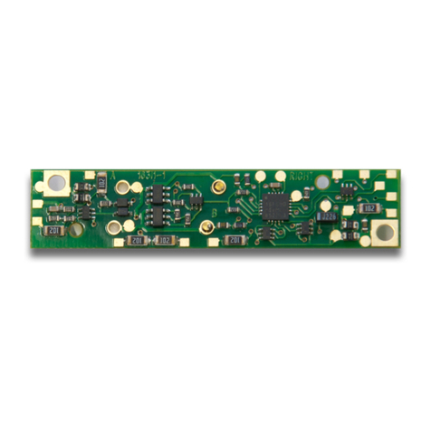
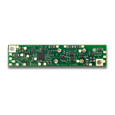
SFX004 SoundbugTM Decoder
Plug N’ Play Sound module for HO, N, O
Locomotives
Preloaded with selectable Steam and
Diesel Sound Schemes
F
Fe
ea
at
tu
ur
re
es
s:
:
nPlug N’ Play sound module for Digitrax DH165 series decoders
nStationary and under-layout sound
nDigitrax SoundFX®Sound System-Your locomotives will sound like the
real thing with SoundFXTM
Customizable 8 Bit Sound
3 simultaneous voices
Downloadable Sound with Digitrax PR2 and SoundLoader software
4 Megabit Sound Memory
Playable F2/Whistle option with DT400 Throttle
1 Watt Sound Output
Cam input-synchronized steam-chuff option for steam locos
nSmart Power Management-no more booster or programmer shutdowns! No
extra equipment needed to program or run
nProgram CVs using any Digitrax Compatible decoder programmer with-
out having to buy any extra equipment
nDirect Mode Programming
nOperations Mode Programming
nDCC Compatible
nRuns on up to 20V track voltage
nDownload sounds using Digitrax PR2 sound programmer
©2007 Digitrax, Inc www.digitrax.com 1
C
Co
om
mp
pl
le
et
te
eT
Tr
ra
ai
in
nC
Co
on
nt
tr
ro
ol
l
R
Ru
un
nY
Yo
ou
ur
rT
Tr
ra
ai
in
ns
s,
,N
No
ot
tY
Yo
ou
ur
rT
Tr
ra
ac
ck
k!
!
HO, N, O and Stationary
SFX004: Plug N’ Play SoundFX® Decoder
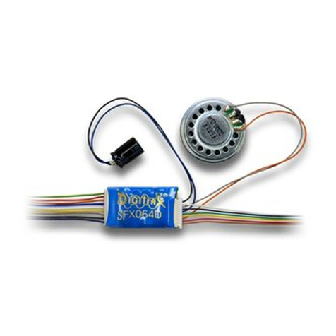
With 28mm Speaker & 330uF Capacitor
©2007 Digitrax, Inc www.digitrax.com 2
P
Pa
ar
rt
ts
sL
Li
is
st
t
1 SFX004 Decoder with SoundFX®1 Instruction sheet
2 2/56 x 1/4” mounting screws
Attached 28mm 32 Ohm speaker and 330 uF capacitor
I
In
ns
st
ta
al
ll
la
at
ti
io
on
nI
In
nf
fo
or
rm
ma
at
ti
io
on
n
For additional resources see Digitrax Decoder Manuals for test procedures,
installation instructions, programming and other technical information. Digitrax
manuals and instructions are updated periodically. Please visit
www.digitrax.com for the latest versions, technical updates and additional loco-
motive-specific installation instructions.
I
In
ns
st
ta
al
ll
la
at
ti
io
on
nI
In
ns
st
tr
ru
uc
ct
ti
io
on
ns
s
1) Identify the correct orientation and mounting side and of the DH165 series
decoder to plug this sound module into. There is text saying “SFX here”
etc,. The SFX004 must only be mounted from the correct side and orienta-
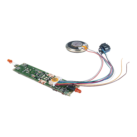
tion, for each of the DH165 host decoders. For convenience, current pho-
tographs of DH165 series decoders and attached SFX sound Bug units
are shown at the following address: www.digitrax.com/soundbuginstall
2) With correct orientation noted from step 1, align the dual row of SFX004
connector pins to the matching holes in the DH165 host PCB. Apply gentle
and firm pressure behind the SFX004 connector to engage the pins until the
black plastic connector base almost touches the DH165 host PCB. (The first
pin insertion may take slightly more force to engage).
3) Screw in the two 2/56 screws from the DH165 host PCB down through the
SFX004 to ensure the module is retained and parallel to the DH165 host.
C
Co
om
mp
pl
le
et
te
eT
Tr
ra
ai
in
nC
Co
on
nt
tr
ro
ol
l
R
Ru
un
nY
Yo
ou
ur
rT
Tr
ra
ai
in
ns
s,
,N
No
ot
tY
Yo
ou
ur
rT
Tr
ra
ac
ck
k!
!
330 uF capacitor and
28mm 32 Ohm speaker
SFX004 8pin Host connector, also showing Speaker and 330uF Capacitor
Figure 1: SFX004 Decoder
8 pin Host connector
©2006 Digitrax, Inc www.digitrax.com 3
4) Mount the attached 28mm speaker in an appropriate sound enclosure. Be
sure to inspect the speaker diaphram for magnetic debris or damage, which
will affect sound quality. Other speakers may be subsitituted in combina-
tions as long as the total impedance on the Orange/Gray wires is 8 ohms or
greater.
5) Mount the 330uF/25V electrolytic energy-storage capacitor. It is often easi-
est to use double-sided tape to locate and secure this capacitor. Be sure not
to short the capacitor case or leads to the track leads or locomotive frame,
or damage to the decoder may result.
6) For Steam units with a synchronization cam capability, connect the White
CAM lead to the cam output connection, and program CV133 to 128 for
external CAM operation.
7) Inspect the installation before testing the sounds and replacing the shell.
Take extra care to inspect that the SFX/SoundBug is clear of any moving
parts such as e.g. flywheels in many of the possible locomotive installa-
tions. In most older units tested, using the DH165A0 and SFX004 combina-
tion, there is typically 1 to 2mm of flywheel clearance, if the Soundbug is
correctly mounted flush and parallel to the host DH165 decoder. Space up
or shim the DH165 series decoder to ensure an adequate separation with no
binding.
8) Connect DCC track power from a compatible DCC system and select the
factory default address 03 to enable SFX sounds for testing
9) Be sure F8 is OFF, and then press F1(bell) or F2 (whistle/horn) ON to hear
these associated sounds.
10) Customize sounds by programming Sound CV’s to adjust the desired con-
2
24
44
43
3T
Tr
ra
an
ns
sm
mi
it
tt
te
er
rR
RD
DT
T8
85
50
0-
-8
87
72
2-
-9
98
89
90
0
P
Pa
an
na
am
ma
aC
Ci
it
ty
y,
,F
Fl
l3
32
24
40
04
4F
F8
85
50
0-
-8
87
72
2-
-9
95
55
57
7
w
ww
ww
w.
.d
di
ig
gi
it
tr
ra
ax
x.
.c
co
om
mE
Es
sa
al
le
es
s@
@d
di
ig
gi
it
tr
ra
ax
x.
.c
co
om
m
SFX004 installation in Atlas
U33 Diesel with
preexisting DH165 Decoder
Figure 2: SFX004 Placement
©2007 Digitrax, Inc www.digitrax.com 4
figurations, as shown in the following tables of Sound FX CVs. Sound
schemes other than the default Steam (CV60=0) or Diesel (CV60=1)
schemes may be loaded by using a Digitrax PR2 Sound FX Programmer.
Note: For standalone operation without a DH165 series host decoder, DCC
track power may be connected to the two gold ringed pads (see page 10)
with holes that the two 2/56 screws engage on the Soundbug. Do not short
or connect to any other of the 8 pin connector pins.
U
Us
si
in
ng
gt
th
he
eS
SF
FX
X0
00
04
4w
wi
it
th
ho
ot
th
he
er
rD
DC
CC
Cd
de
ec
co
od
de
er
rs
s
The sound project loaded into this decoder may be operated independently of
any other DCC motor or function decoder. If another non-Sound FX com-
patible DCC decoder is connected to the track leads then CV readback of
SFX004 Sound CV’s and PR2 SoundTest modes may not be possible. Note
that it is always possible to Write CV values using Operations mode or a
Service Mode programming track, even if CV Read is inoperative.
If the connected function loads are insufficient for CV readback with a PR2 or
an incompatible DCC decoder is also connected, it is still possible to down-
load a complete sound project by using the large green “program project”
icon. in the SoundLoader program.
S
Sp
pe
ea
ak
ke
er
rM
Mo
ou
un
nt
ti
in
ng
ga
an
nd
dB
Ba
af
ff
fl
le
e/
/E
En
nc
cl
lo
os
su
ur
re
es
s.
.
The sound performance of any attached speaker(s) is greatly affected by the
mounting system and required baffle or rear enclosure.
The baffle is used to isolate to speaker diaphragm front sound waves from the
out of phase rear sound waves. This minimises sound cancellation, particularly
at lower frequencies. For most efficient sound generation, the volume of the
baffle should be as large as practically possible, and the baffle walls should be
acoustically rigid so not to allow acoustic interference.
Practical baffle materials are plastic, cardboard and even sheetmetal. Common
items such as cardboard tubes or 35mm film canisters may be modified and
trimmed to create reasonable baffles. Commercial baffles are also available in
many sizes to match many types of speakers, such as a “TDS Enclosure 1.10”
diameter” from Tony’s Train Exchange [1-800-978-3472] unit that will match
the 28mm factory speaker of the SFX004
Most HO or O scale or similar locomotives have limited internal volume within
the shell, so the choice of speaker mounting requires some ingenuity for good
sound performance and volume. An example of a commercial molded baffle in
a ready-to-run locomotive is the Kato HO F40-PH, where the 28mm speaker
clips into an enclosure at the upper rear of the locomotive shell.
C
Co
om
mp
pl
le
et
te
eT
Tr
ra
ai
in
nC
Co
on
nt
tr
ro
ol
l
R
Ru
un
nY
Yo
ou
ur
rT
Tr
ra
ai
in
ns
s,
,N
No
ot
tY
Yo
ou
ur
rT
Tr
ra
ac
ck
k!
!
©2007 Digitrax, Inc www.digitrax.com 5
C
Cu
us
st
to
om
mi
iz
zi
in
ng
gY
Yo
ou
ur
rD
De
ec
co
od
de
er
r
Your Digitrax SFX004 SoundbugTM is ready to run and will operate and gener-
ate sound using address 03 with no additional programming. On your Digitrax
system, simply select the locomotive’s address and the sound will start. On
some DCC systems, it is necessary to select the locomotive address AND send
a command to start the sounds.
When used in conjunction with a separate DCC motor decoder in a single loco-
motive it is most practical to program both decoders to the same address and
operating modes.
For a more prototypical railroading experience, your decoder can be cus-
tomized for your specific locomotive by programming some of the
Configuration Variables, or CVs, available. Digitrax Sound decoders can be
programmed using either the direct method on a programming track or with the
operations mode using the main line. See the Digitrax Decoder Manual or the
Digitrax web site for more information.
Intial Test and Programming: This decoder is preprogrammed and tested
with a Steam locomotive sound scheme, and is ready to operate on factory
default address 03. Before customizing the decoder it is useful to run it on
the factory default address 03 to check the installation. The following sec-
tions show how to change the locomotive address and customize the
decoder
For more information on decoder installation and programming techniques and
examples visit the www.digitrax.com
C
Ch
ha
an
ng
gi
in
ng
gt
th
he
eD
De
ec
co
od
de
er
rA
Ad
dd
dr
re
es
ss
s
The first CV most people change is the decoders address. This lets you inde-
pendently control each loco with its own unique address. Digitrax decoders are
shipped with CV01 (AD2), the two digit address, set to 03. Following is a brief
description of how to change the decoder address with a Digitrax DT series
throttle. See your Starter Set Manual for complete programming instructions.
1. Place the loco on the programming track or on the main line.
2. Enter the programming mode using your DCC system/throttle. On DT400
press PROG until you see “Pd” if using a programming track or “Po” if
using the main line.
3. Use your throttle to choose the address you want to set up for the decoder.
On the DT400 use the left knob to dial AD2 for two digit programming, use
the right knob to dial up the address, click the right knob to change to AD4
for programming 4 digit addresses.
2
24
44
43
3T
Tr
ra
an
ns
sm
mi
it
tt
te
er
rR
RD
DT
T8
85
50
0-
-8
87
72
2-
-9
98
89
90
0
P
Pa
an
na
am
ma
aC
Ci
it
ty
y,
,F
Fl
l3
32
24
40
04
4F
F8
85
50
0-
-8
87
72
2-
-9
95
55
57
7
w
ww
ww
w.
.d
di
ig
gi
it
tr
ra
ax
x.
.c
co
om
mE
Es
sa
al
le
es
s@
@d
di
ig
gi
it
tr
ra
ax
x.
.c
co
om
m
©2007 Digitrax, Inc www.digitrax.com 6
4. Complete address programming. On DT400 press ENTER. Note: CV29
must also be programmed to enable 4 digit addressing, this is done automat-
ically by the DT300 & DT400 but not on earlier throttles.
U
Us
si
in
ng
gt
th
hi
is
sd
de
ec
co
od
de
er
ri
in
no
ot
th
he
er
rl
lo
oc
co
om
mo
ot
ti
iv
ve
es
s
The factory supplied sound project loaded into the SFX004 is for a Steam
(default) or SD38-2 diesel locomotive, selectable with the value in CV60.
If you want to install it in a different locomotive, you can simply load a dif-
ferent sound project for that type of locomotive. The cam input is available
for steam installations where you want to synchronize chuffing.
D
Di
ig
gi
it
tr
ra
ax
xL
Lo
oc
co
oM
Mo
ot
ti
io
on
n
®
S
Sy
ys
st
te
em
m
The SFX004 does not have a motor drive capability but uses the DCC CV’s
associated with motor drive to synchronize the generation of prime move
sounds.
M
Mo
om
me
en
nt
tu
um
m-
-C
CV
V0
03
3&
&C
CV
V0
04
4
Momentum is part of DCC decoder operation. Acceleration is controlled by
CV03 and deceleration by CV04. Both come from the factory set to 000/x00. A
range of 000/x00 to 031/x1F is available for both accel and decel. We recom-
mend that you try CV03:003/x03 and CV04:000/x00 as a starting point for
experimenting with momentum.
S
Sp
pe
ee
ed
dT
Ta
ab
bl
le
es
s-
-H
Ho
ow
wt
th
he
eL
Lo
oc
co
oR
Re
es
sp
po
on
nd
ds
st
to
ot
th
he
eT
Th
hr
ro
ot
tt
tl
le
e
With Digitrax LocoMotion, there are two types of speed tables: 3 Step Tables
and High Resolution 28 Step Tables. Please see your Digitrax Decoder Manual
for a discussion of the 28 Step Tables. The 3 Step Tables are set up by program-
ming 3 CVs: Start Voltage (CV02), Mid point Voltage (CV06) and Max Voltage
(CV05). These values are set at 000/x00 at the factory. All have a range of val-
ues from 000/x00 to 255/xFF. We recommend the following CV values as a
starting point for experimenting with speed tables.
O
Ot
th
he
er
rL
Lo
oc
co
oM
Mo
ot
ti
io
on
n
®
F
Fe
ea
at
tu
ur
re
es
s:
:S
Sw
wi
it
tc
ch
hi
in
ng
gS
Sp
pe
ee
ed
d,
,N
No
or
rm
ma
al
lD
Di
ir
re
ec
ct
ti
io
on
no
of
f
T
Tr
ra
av
ve
el
l
Switching speed is controlled by CV54. The factory setting is 000/x00 for
OFF. To turn on the switching speed feature, program CV54 to a value of
001/x01. When this feature is on, use F6 to activate and deactivate switching
speed. When switching speed is ON and F6 is ON, the switching speed feature
is on. With the feature on the throttle’s target speed is effectively reduced by
about 50% and the effects of accel and decel programmed into the decoder are
reduced by 1/4. This is useful for yard switching operations.
C
Co
om
mp
pl
le
et
te
eT
Tr
ra
ai
in
nC
Co
on
nt
tr
ro
ol
l
R
Ru
un
nY
Yo
ou
ur
rT
Tr
ra
ai
in
ns
s,
,N
No
ot
tY
Yo
ou
ur
rT
Tr
ra
ac
ck
k!
!
©2007 Digitrax, Inc www.digitrax.com 7
Normal Direction of Travel is controlled by CV29. See your decoder manual
for additional information on the settings for CV29.
D
De
ec
co
od
de
er
rR
Re
es
se
et
tC
CV
V0
08
8
Decoder reset lets you reset all CV values to the initial factory settings. To
reset all CV values, program CV08 to a value of 008/x08. You also have the
option of resetting all values except the 28 speed step tables. To do this,
program CV08 to a value of 009/x09.
D
Di
ig
gi
it
tr
ra
ax
xS
So
ou
un
nd
dF
FX
XT
TM
MS
Sy
ys
st
te
em
m
Digitrax SoundFXTM lets you make your locos sound like the real thing!
The SoundFX sound CVs in the range of CV140 to CV256 let you customize
your decoder without having to reprogram or change the installed sound
scheme.
Standard decoder CVs in the range of CV01 to CV120 operate the same as for
a non-sound FX3Digitrax decoders (they control motor and light functions
etc.) CV58 is used as Master Volume, and CV60 is used to select an alter-
nate scheme, if provided in the sound project.
Sound CV155 is provided to select Diesel engine “notching” modes. The
default of CV155= 00 provides “automatic notching” that changes the
diesel RPM settings at 8 distinct throttle speeds that are controlled by Sound
CV132.
Sound CV155=01 selects “semi-automatic notching” mode that allows F6 ON
to increase the notch from the current throttle setting and F7 ON to decrease
back towards the lowest current throttle notch setting.
Sound CV155=02 selects “manual notching” mode that allows F6 ON to
increase the notch setting and F7 ON to decrease the notch setting irrespec-
tive of the throttle setting, which controls just the motor speed.
The decoder’s sound scheme can be reloaded using a Digitrax PR2 program-
mer and a sound project file (for example AC4400.spj) from the Digitrax
Sound Depot web site. Typical sound downloads take between 50 and 100
seconds depending on the project complexity and file size.
The following tables show the CVs used in this decoder version and how it is
set up at the factory to operate various sounds using your throttle.
2
24
44
43
3T
Tr
ra
an
ns
sm
mi
it
tt
te
er
rR
RD
DT
T8
85
50
0-
-8
87
72
2-
-9
98
89
90
0
P
Pa
an
na
am
ma
aC
Ci
it
ty
y,
,F
Fl
l3
32
24
40
04
4F
F8
85
50
0-
-8
87
72
2-
-9
95
55
57
7
w
ww
ww
w.
.d
di
ig
gi
it
tr
ra
ax
x.
.c
co
om
mE
Es
sa
al
le
es
s@
@d
di
ig
gi
it
tr
ra
ax
x.
.c
co
om
m
©2007 Digitrax, Inc www.digitrax.com 8
C
Co
om
mp
pl
le
et
te
eT
Tr
ra
ai
in
nC
Co
on
nt
tr
ro
ol
l
R
Ru
un
nY
Yo
ou
ur
rT
Tr
ra
ai
in
ns
s,
,N
No
ot
tY
Yo
ou
ur
rT
Tr
ra
ac
ck
k!
!
CV#
Used For
[Range]
default val
01
2 Digit Address
03
11
Sound Time Out, 06=Sound ends when
loco address is de-selected, 00=Sound
stays on after loco is de-selected
06
29
Configuration Register
06
49
Forward Light (F0F)-Headlight
0
50
Reverse Light (F0R)-Reverse Light
0
51
Function 1
0
52
Function 2
0
58
Master Volume (F8 used for Mute)
[0-15] 9
60
Select Sound Scheme
0
132
Notch Rate
127
135
Mute Volume
0
140
Prime Mover/Chuff Volume
[0-64] 60
141
Bell Volume (Min=0, max=64)
25
142
Horn/Whistle Volume (Min=0, max=64)
60
143
Time-Scattered Air Effects Volume
[0-64] 30
145
Misc vols
[0-64] 40
146
Bell Ring Rate (1=24 milliseconds)
[1-100] 07
147
Air Drier Rate (1=about 2 seconds)
[1-64] 02
148
Compressor Run Rate
30
149
Air Compressor On Time
20
150
Horn/Whistle Setup (Default=0, Playable
Horn=1, Alternate Horn=2)
0
151
Auto Coupler Sequence Threshold Value-
Peak speed to allow auto coupler/brake
when direction change occurs and F3 is
ON
[0-60] 48
152
Project Author ID, Digitrax=221
221
153
Project ID Steam/SD38_2
02
154
Steam Blowdown / Safety volume
[0-64] 60
155
Notching/Slip Mode: 00=Automatic,
01=Semi-Automatic, 02=Manual
00
©2007 Digitrax, Inc www.digitrax.com 9
S
So
ou
un
nd
dF
FX
XD
DC
CO
Op
pe
er
ra
at
ti
io
on
nM
Mo
od
de
e
Digitrax SoundFX deccoders will operate on smooth DC power. The sound will
not start until approximately 5 volts is applied to the track and there will be no
“start up sound.”
2
24
44
43
3T
Tr
ra
an
ns
sm
mi
it
tt
te
er
rR
RD
DT
T8
85
50
0-
-8
87
72
2-
-9
98
89
90
0
P
Pa
an
na
am
ma
aC
Ci
it
ty
y,
,F
Fl
l3
32
24
40
04
4F
F8
85
50
0-
-8
87
72
2-
-9
95
55
57
7
w
ww
ww
w.
.d
di
ig
gi
it
tr
ra
ax
x.
.c
co
om
mE
Es
sa
al
le
es
s@
@d
di
ig
gi
it
tr
ra
ax
x.
.c
co
om
m
Func
Used For
Notes
F0
Lights
F1
Bell
F2
Horn/Whistle
CV150 sets mode
F3
Coupler crash
Auto coupler/brake set by
CV151 max speed
F4
Air feature disable
F4 off enables pop-off,
drier and starts
compressor/airpump
F5
Diesel= Dynamic
brake Fans
Steam=Waterpump
turbine
F6
Diesel=Notch UP
Steam=Blowdown
Notch UP if CV155=01 or
02
F7
Crossing Gate
Airhorn or;
Diesel=Notch
DOWN
Steam=Wheelslip
Notch DOWN, if
CV155=01 or 02
(Crossing Gate active if
in Diesel mode and
CV155=0)
F8
Mute Control
F8 ON is mute
F9
Brake squeal
F10
Crossing Gate
Airhorn Sequence
F11
Steam=Greaser
F12
Steam=Safety
Blowoff
©2007 Digitrax, Inc www.digitrax.com 10
S
SF
FX
X0
00
04
4I
In
nS
St
ta
at
ti
io
on
na
ar
ry
yo
or
rU
Un
nd
de
er
r-
-l
la
ay
yo
ou
ut
tO
Op
pe
er
ra
at
ti
io
on
n
The SFX004 can be used in a
stand alone configuration as well.
In these situations just connect
pins 9 and 10 to the track and
address the device normally.
S
SF
FX
X0
00
04
4T
Tr
ro
ou
ub
bl
le
es
sh
ho
oo
ot
ti
in
ng
g
If the sound does not start in the decoder
1. Make sure you have selected the locomotive on a throttle. The sound will
not run unless the locomotive is addressed in the system.
2. Check your installation to make sure the decoders are installed properly.
If the sound output sounds distorted
1. Check the speaker cone for magnetic debris that may have collected there.
Debris on the speaker will cause a loss of sound quality and must be removed.
2. Be sure that the CV58 volume is not set at a level that is too high for the
speaker. For impedances below 32ohms (e.g. 8 to 30 ohms) set the volume set-
ting lower to ensure the 1 watt output rating is not exceeded.
If the sound in your decoder shuts down after you stop it and you are not
using a Digitrax system for control. On some DCC systems decoders are not
addressed by DCC packets after the locomotive is set to 0 speed. In this case
after the CV11 timeout elapses (6 second default), sound will “shutdown.”. To
defeat this feature, set CV11=00 to remove the timeout and shutdown. To make
sounds, the decoder must have a command addressed to it at least once.
If you have trouble reading back CV’s on the programming track, this may
be due to insufficient current draw by the SFX004 for the programmer you are
using. Of course you can always just re-program the CV value into a CV to
get the desired results, even though reading CV’s does not work. OPs mode is
recommended for programming all CVs except CV01, CV17 & CV18 (2 digit
and 4 digit addresses). If a second DCC decoder is present that is not Sound
FX compatible, then correct readback of CV data is not possible, since the
NMRA CV readback method was not originally designed for multiple decoder
readback.
The SFX004 plays a Diesel scheme, but I want the default steam scheme. If
C
Co
om
mp
pl
le
et
te
eT
Tr
ra
ai
in
nC
Co
on
nt
tr
ro
ol
l
R
Ru
un
nY
Yo
ou
ur
rT
Tr
ra
ai
in
ns
s,
,N
No
ot
tY
Yo
ou
ur
rT
Tr
ra
ac
ck
k!
!
Pin 9
Track Power
Pin 10
Track Power
©2007 Digitrax, Inc www.digitrax.com 11
the factory scheme has not been erased, program CV60 to a value of 0 to rese-
lect the Steam scheme. Alternatively set CV60 to 01 to change to the SD38-2
sound scheme.
I have loaded a new scheme but the CV’s and Functions are not what I
expected. Load the sound project you programmed and then select the
“view>project description” menu and then read the text file on the screen that
defines how that project in particular uses CV’s and Functions for sound gener-
ation and configuration.
I cannot run the “SoundTest” feature of the SoundLoader program used
in conjunction with a PR2 Programmer. If the SoundbugTM is combined with
a DCC decoder that is not fully SFX compatible, then it may not be possible
for the SoundTest feature to activate properly. Of course, it is still possible to
hear and exercise the sound scheme by placing the programmed units on a reg-
ular DCC track, and operating the functions, etc. Also, it is possible to program
the Soundbug with new sound projects using the PR2, and non-SFX compatible
decoders should have the Analog Mode conversion capability in CV29 turned
OFF.
W
Wa
ar
rr
ra
an
nt
ty
y&
&R
Re
ep
pa
ai
ir
r
All warranties on Digitrax products are limited to refund of purchase price,
repair or replacement at Digitrax’s sole discretion. Except as expressly stated in
the full warranty statement, there are no warranties, express or implied, includ-
ing but not limited to any warranties of merchantability or fitness for a particu-
lar purpose. For complete warranty details see www.digitrax.com.
Damaged decoders should be returned directly to Digitrax for repair.
Incorporates elements of US Patents 6220552, 6729584, other patents
pending.
Digitrax, Inc. is not responsible for unintentional
errors or omissions in this document.
2
24
44
43
3T
Tr
ra
an
ns
sm
mi
it
tt
te
er
rR
RD
DT
T8
85
50
0-
-8
87
72
2-
-9
98
89
90
0
P
Pa
an
na
am
ma
aC
Ci
it
ty
y,
,F
Fl
l3
32
24
40
04
4F
F8
85
50
0-
-8
87
72
2-
-9
95
55
57
7
w
ww
ww
w.
.d
di
ig
gi
it
tr
ra
ax
x.
.c
co
om
mE
Es
sa
al
le
es
s@
@d
di
ig
gi
it
tr
ra
ax
x.
.c
co
om
m
Made in U.S.A.
307-SFX004-INS 1k/07/07
Plug N’ Play SoundFX® Decoder
2443 Transmitter Rd
Panama City, FL
32404-3157
www.digitrax.com
T850-872-9890
F850-872-9557

Other Digitrax Media Converter manuals
Digitrax DN163I0 User manual

Digitrax

Digitrax DN163I0 User manual

Digitrax SoundFX SFX0416 User manual

Digitrax

Digitrax SoundFX SFX0416 User manual

Digitrax SoundFX SDXN146K1E User manual

Digitrax

Digitrax SoundFX SDXN146K1E User manual

Digitrax DH166P User manual

Digitrax

Digitrax DH166P User manual

Digitrax DZ123M0 User manual

Digitrax

Digitrax DZ123M0 User manual

Digitrax DN166I1D User manual

Digitrax

Digitrax DN166I1D User manual

Digitrax DZ143 User manual

Digitrax

Digitrax DZ143 User manual

Digitrax DN163A3 User manual

Digitrax

Digitrax DN163A3 User manual

Digitrax SDN144K1E User manual

Digitrax

Digitrax SDN144K1E User manual

Digitrax SDH104K1A User manual

Digitrax

Digitrax SDH104K1A User manual

Digitrax DN163PS User manual

Digitrax

Digitrax DN163PS User manual

Digitrax DZ126Z1 User manual

Digitrax

Digitrax DZ126Z1 User manual

Digitrax DN163I1C User manual

Digitrax

Digitrax DN163I1C User manual

Digitrax DS44 User manual

Digitrax

Digitrax DS44 User manual

Digitrax PR3 XtRa User manual

Digitrax

Digitrax PR3 XtRa User manual

Digitrax SoundFX SDN144A0 User manual

Digitrax

Digitrax SoundFX SDN144A0 User manual

Digitrax DN166I1A User manual

Digitrax

Digitrax DN166I1A User manual

Digitrax DN163A1 User manual

Digitrax

Digitrax DN163A1 User manual

Digitrax DS64 User manual

Digitrax

Digitrax DS64 User manual
Digitrax DN163A2 User manual

Digitrax

Digitrax DN163A2 User manual

Digitrax DH166MT User manual

Digitrax

Digitrax DH166MT User manual

Digitrax 3 Series User manual

Digitrax

Digitrax 3 Series User manual
Digitrax DZ123MK1 User manual

Digitrax

Digitrax DZ123MK1 User manual

Digitrax DS51K1 User manual

Digitrax

Digitrax DS51K1 User manual

Popular Media Converter manuals by other brands

Meinberg GPSGEN1575/MP Characteristics

Meinberg

Meinberg GPSGEN1575/MP Characteristics

Whyte WT91-10 instruction manual

Whyte

Whyte WT91-10 instruction manual

ADF Web HD67D20-B2 user manual

ADF Web

ADF Web HD67D20-B2 user manual

TLS TBD.DMX-4C-RJ45 user manual

TLS

TLS TBD.DMX-4C-RJ45 user manual

AJA IPT-1G-SDI Installation and operation guide

AJA

AJA IPT-1G-SDI Installation and operation guide

tams elektronik WD-1 manual

tams elektronik

tams elektronik WD-1 manual

Philips BTB2462 user manual

Philips

Philips BTB2462 user manual

XL Systems 0001916 quick start guide

XL Systems

XL Systems 0001916 quick start guide

JDS Labs OL DAC operating instructions

JDS Labs

JDS Labs OL DAC operating instructions

SMAR if303 Operation, maintenance & instruction manual

SMAR

SMAR if303 Operation, maintenance & instruction manual

DELTACAST DELTA-neo N2H user manual

DELTACAST

DELTACAST DELTA-neo N2H user manual

Axis P7224 installation guide

Axis

Axis P7224 installation guide

Digitus DN-82020-1 manual

Digitus

Digitus DN-82020-1 manual

C&H PXI 12-Bit ADC PX453S Specifications

C&H

C&H PXI 12-Bit ADC PX453S Specifications

Converters.TV 15267 Operation manual

Converters.TV

Converters.TV 15267 Operation manual

VigilLink VL-SP-14H-1 user manual

VigilLink

VigilLink VL-SP-14H-1 user manual

Parasound P/DD-1550 Owner's manual addendum

Parasound

Parasound P/DD-1550 Owner's manual addendum

Lasonic I931 Specifications

Lasonic

Lasonic I931 Specifications

manuals.online logo
manuals.online logoBrands
  • About & Mission
  • Contact us
  • Privacy Policy
  • Terms and Conditions

Copyright 2025 Manuals.Online. All Rights Reserved.