Grainger 7J823 Service manual

1
Operating Instructions and Parts Manual
7J823, 7J824
12N408,12N409,12N410
12N411,12N412,12N413
Please read and save these instructions. Read carefully before attempting to operate or maintain the product described. Protect yourself
and others by observing all safety information. Failure to comply with instructions could result in personal injury and/or property damage!
Retain instructions for future reference.
L Impulse Sealers
Description
L impulse sealers are specially designed for use in production
environments for small to medium size packages. The sealer
perforates the film for easy shrinking without air pockets, and it
seals two sides simultaneously to fully enclose the product in one
simple step.
General Safety Information
WARNING: Do not use this product before reading and
understanding these operating instructions.
WARNING: Do not use in damp or wet environments.
WARNING: Do not use inflammable, combustible, or corrosive
environments. Do not use this product to package flammable or
combustible materials.
WARNING: Fine powders may ignite under high temperatures even if they are not inherently combustible. Test new
materials under close supervision before beginning production runs.
WARNING: Only qualified personnel should install and/or service this product.
WARNING: Do not touch heated surfaces.
CAUTION: Failing to properly maintain this product could create hazardous conditions.
NOTE: Modifying this product will void the manufacturer’s warranty.
NOTE: Keep this manual for future reference.
Specifications
Overall
S
ize
Max
Sealing Area
Model
Voltage
Wattage
Length
Width
Height
Width
Length
7J823 115 2500 47.2” 25.9” 36.7” 17.3” 17.3”
7J824 115 2900 59” 31.9” 36.7” 23.25” 23.25”
Properties and Performance of Sealer
SKU Type Seal Capacity
(In.)
Sealing
Width
(In)
Maximum
Film
Thickness
(POF)
Heat
Time
(sec) Volt Watts Weight
(lbs) Includes
7J823
L-Type
Impulse
sealer
17 5/16 X 17
5/16 1/8 0.019 mm 0 ~ 2 115V 2500W Around
225.5 lbs
Sealing Section,
Film Bracket,
and stand
7J824
L-Type
Impulse
sealer
23 1/4 X
23 1/4 1/8 0.019 mm 0 ~ 2 115V 2900w Around
288.2 lbs
Sealing Section,
Film Bracket,
and stand

2
Operating Instructions and Parts Manual
7J823, 7J824
12N408,12N409,12N410
12N411,12N412,12N413
Product Assembly
SKU Includes
Dimension
(LxWxH in)
Overall view
7J823 L-TYPE IMPULSE SEALER
12N408 SEALER- 18" 29.31" x 21.63" x 10.81"
12N409 FILM BRACK-18" 26.56" x 23.6" x 9.25"
12N410 STAND-18" 47.25" x 26" x 27.56"
7J824 L-TYPE IMPULSE SEALER
12N411 SEALER- 24"
35.44" x 27.56" x 10.81"
12N412 FILM BRACK-24" 32.5" x 29" x 9.25"
12N413 STAND-24" 59.06" x 31.88" x 27.56"
Sealing time is adjustable from 0 to 2 seconds.
Seal width is 1/8”
H
W
L
W
L
H
W
L
H
W
H
L
L
W
H
L
W
H
Unpacking and Inspection
Check the packing list to account for all items.
Visually inspect for shipping damage. If damaged,
immediately file a claim with the carrier.
Handle carefully. Utilize proper hoist/lift equipment
to avoid personal injury or damage to property.

3
Operating Instructions and Parts Manual
7J823, 7J824
12N408,12N409,12N410
12N411,12N412,12N413
Setup and Installation
Carefully remove the outer carton and unpack the
legs, casters, and assembly hardware.
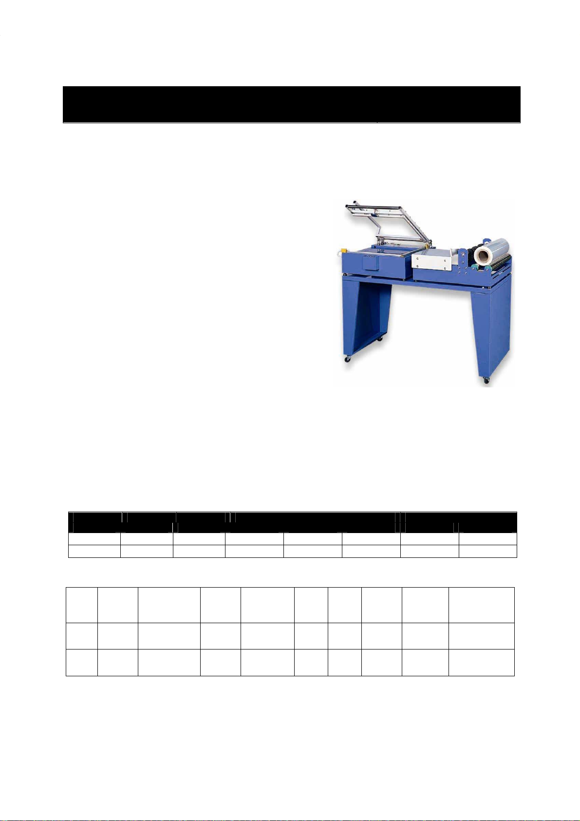
Figure 1
1
In an open workspace, attach legs and casters with
hardware provided.
Select an area for use that is open and free from dust,
flammable materials, or corrosive materials. Position
the sealer table in place so power connections may
be made.
Set the L-sealer on the left side of the work table and
place the film roll holder on the right side.
Plug the L-sealer into a dedicated 115V circuit.
Loading the Shrink Film
1. Most shrink films are centerfolded to allow the
film to envelop the product. Place the roll of film
on the rollers with the fold away from the operator.
2. Run the film through the perforation wheels.
Perforation will eliminate “pillowing” during later
heat shrinking steps but will not be visible after
heat shrinking.
3. Separate the fold, running the upper layer over
the raised platform on the roller table and the
lower layer beneath it.
4. On the L-sealer, adjust the work table height by
lifting up and to the left. The table height should
be set so half the package is above the sealing
element and half is below. The sealer table
should be lower for taller packages.
Operation
NOTE: Keep work area clear of obstructions.
NOTE: Before each use, check the Teflon® cloth and
silicone rubber bar. Replace if worn or damaged.
NOTE: Adjust the sealing timer to the lowest setting
that produces a good seal. Too high of a setting will
produce a poor seal and shorten heating element life.
Figure 2
○
1
○
2
○
3
○
4
○
5
○
6
No.
Panel Function
1 Release LED
Indicates heating/cooling
cycle is still in process.
2 Heat LED Indicates heating element is
on and sealing.
3 Circuit
Breaker Press to reset and consider
moving to a dedicated circuit.
4 Release
Timer Adjusts cooling time after the
heat seal is made.
5 Heat Timer Adjusts heating time.
6 Power Powers all functions.
1. Turn on main power.
2. Feed film into sealing area
and press firmly down
on the bar to create an initial seal. This will serve
to seal the left side of the film, as well as test the
sealing settings.
3. When the bar is pressed down, the Heat LED
and Release LED will come on. The Heat LED
light will turn off as the cooling cycle begins. The
Release LED will then turn off and an audible
indicator will coincide with the arm’s
electromagnet release. Raise the arm.

Operating Instructions and Parts Manual
Operation (continued)
4. A uniform, fully-
welded seal should be produced.
NOTE:
If seal is damaged, incomplete, or not uniform,
or if the bag is sticking to the sealer, refer to
troubleshooting section of this manual
a good seal is achieved.
5. Place a package on the
table of the
such that it is under the upper layer of film
6. Move the package to the L-
sealer, unwinding the
film from right to left as you do so.
should be positioned near the front right corner to
minimize excess film.
7. Press firmly down on the bar
to begin sealing.
8.
At the audible tone, the Release LED turn
and the arm’s electromagnet
will
9.
Raise the arm and remove the sealed package.
10.
Shrink the film using a heat gun or a heated
shrink tunnel.
11. Power off the sealer
when finished.
Maintenance
WARNING: Disconnect power
before performing any
service or repair.
NOTE:
Use original manufacturer’s parts
Weekly Maintenance
K
eep the sealing platform clean and remove any
residue found on the platform or
Teflon
Silicone
spray may be used for this purpose
Check the condition of the silicon
e
or burn. Damaged silicone r
ubber will affect the
quality of the seal.
Monthly Maintenance
Place a drop or two of oil on the bearing for the film
roller cradle.
Check screws, nuts, and bolts for loose connections.
Other Maintenance
When changing the Teflon tape
, be sure that the
entire surface under the heating e
lement is covered
with Teflon. B
end the excess Teflon
ends to prevent the heating e
lement from breaking
or from grounding to the frame.
4
Operating Instructions and Parts Manual
12N408,12N409,12N410
12N411,12N412,12N413
welded seal should be produced.
If seal is damaged, incomplete, or not uniform,
or if the bag is sticking to the sealer, refer to
troubleshooting section of this manual
and repeat until
table of the
roller holder
such that it is under the upper layer of film
.
sealer, unwinding the
film from right to left as you do so.
The package
should be positioned near the front right corner to
to begin sealing.
At the audible tone, the Release LED turn
s off
will
release.
Raise the arm and remove the sealed package.
Shrink the film using a heat gun or a heated
when finished.
before performing any
Use original manufacturer’s parts
.
eep the sealing platform clean and remove any
Teflon
tape.
spray may be used for this purpose
.
e
rubber for wear
ubber will affect the
Place a drop or two of oil on the bearing for the film
Check screws, nuts, and bolts for loose connections.
, be sure that the
lement is covered
end the excess Teflon
down on both
lement from breaking
,
Troubleshooting
Figure 3
7J823, 7J824
12N408,12N409,12N410
12N411,12N412,12N413

5
Operating Instructions and Parts Manual
7J823, 7J824
12N408,12N409,12N410
12N411,12N412,12N413
Troubleshooting
Symptom
Cause
Solution
Power switch is
on but not lit
Power disconnection
Sealer circuit breaker has tripped
P
ower cord is
damaged
Check the plug connection or source circuit breaker
Reset the sealer circuit breaker
R
eplace or repair the cord
Power switch
and Heat LED
are lit, but no
seal is made
Heating element is broken
Spring hook or mounting spring is loose
or has poor contact connections
Terminals of the heating element do not
make a good contact
Limit switch is not engaging
Defective limit switch
Replace the heating element
Clean or tighten spring hook connections
Clean the terminals and adjust if needed
Adjust limit switch position
Replace limit switch
Teflon cloth is
burned or
heating wire
broken
Printed circuit board is damaged
Excessively high heating timer setting.
Replace the printed circuit board
Decrease heating timer setting. Too high a setting
will produce a poor seal and shorten heating element
life.
Seal is broken,
damaged, or
wrinkled
Dirty or damaged silicone rubber or
Teflon tape.
Heat time is set too high.
Insufficient cooling time.
Clean or replace silicone rubber or Teflon tape.
Decrease time and try again.
Increase release timer setting. If release timer is at
its highest setting, manually holding the sealing bar
for 1 to 2 seconds after the beep may be needed.
Partial or
uneven seal Dirty or damaged silicone rubber or
Teflon tape.
Sealing time is too short.
Seal is not being completed properly.
Clean or replace silicone rubber or Teflon tape.
Increase timer and try again.
Continue to apply pressure to the bar 1-2 seconds
after the red light has gone out.
Bag sticks to
silicone rubber
or heating
element
Sealing time is too long.
Dirty or damaged silicone rubber or
Teflon tape.
Decrease timer and try again.
Clean or replace silicone rubber or Teflon tape.

6
Operating Instructions and Parts Manual
7J823, 7J824
12N408,12N409,12N410
12N411,12N412,12N413
Figure 4
Part Description Part Description Part Description
1 Frame 16 Magnet Plate Base 31 Hook Shaft Cover
2 Adjustable Platform 17 Heating Element Base 32* Limit Switch
3 Control Switch Board 18 Element Radius Spacer 33 Arm Spring
4 Sealing Arm Frame 19 Limit Switch Plate 34* Silicone Rubber Strip
5 Right Hinge Cover 20 Arm Handle 35 M5*50 Screw
6 Left Hinge Cover 21 Handle Rod 36 Spring
7 Right Hinge Bracket 22 Handle Cap 37 Bushing Sleeve
8 Left Hinge Bracket 23 Hinge/Pivot Pins 38 Foot
9 Electromagnet Cover 24 Element Radius (Copper) 39 20x20 Cap
10 Side Silicone Rubber Strip Base 25 Magnet Plate Base Bracket 40* Transformer
11 Front Silicone Rubber Strip Base
26* Heating Wire Element 41* Printed Circuit Board
12 Sealing Aluminum Base- Side 27 Ceramics 42* Teflon tape
13 Sealing Aluminum Base- Front 28 Element Hook Cover 43 Electromagnet
14 Sealing wire board holder 29* Control Panel Switch Set
15 Magnet Plate 30 Element Hook
* - Denotes that the part is available as a replacement part.

7
Operating Instructions and Parts Manual
7J823, 7J824
12N408,12N409,12N410
12N411,12N412,12N413
Figure 5
Part Description Part Description Part Description
1 Frame 8 Perf. Rod Bracket 15* Perf. Wheel Ring
2 Work table 9 Adj. Film Bracket Locator Plate 16 Foam Gel Fixed Ring
3 Carrier Adjustment Board 10 Fixed Film Bracket Locator Plate 17 Foam Gel Bushing
4 Film Rollers 11 Film Bracket Locator Pin 18 Knob (M6*L20 Thread)
5 Perf. Wheel Rod 12 Perf. Wheel Cover 19 Knob (M8*L20 Thread)
6 Carrier Adjustment Rods 13 Perf. Wheel Bushing 20 M8 Foot
7 Perf. Rod Bracket 14* Foam Gel
* - Denotes that the part is available as a replacement part.
Replacement Parts
Ref
.
Number Description
Part Number
for model:
7J823
7J824
26, 34, 42
Heating Wire Element Kit*
13F538
13F539
29
Control Panel Switch Set
MH
12N408
02G
MH
12N408
02G
32 Limit Switch MH12N40803G MH12N40803G
40 Transformer MH12N40801G MH12N40801G
41 Printed Circuit Board MH12N40804G MH12N40804G
14 & 15 Foam Gel & Perf. Wheel Ring Kit (incl. 4 of each) MH12N40901G MH12N40901G
-
Caster
MH
12N4
1001G
MH
12N4
1001G
* - Silicone rubber strip may need to be cut to length for some models. Use caution when cutting.
This manual suits for next models
7
Table of contents