7
WEBCS-1 09/18
PROPER VENTING
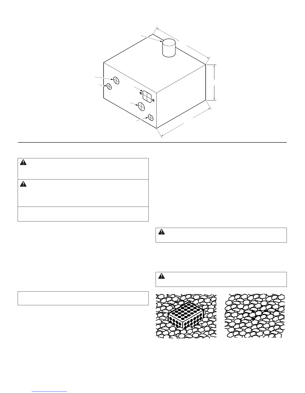
ACCEPTABLE MEDIA
Do not use any other material as media in the re feature
other than those listed below.
• Lava rock no smaller than 1/2" average diameter.
• Fireglass specically designed and approved for re features.
•
Stones of man made materials (refractory) designed for re pits.
Media used in the re feature enhances the look of the ame
and improves the re pit performance. As gas is emitted from
the burner the media helps mix air with fuel resulting in a more
uniform ame and a cleaner burn. The media will also help
spread the ame across all areas of the burner resulting in a
faster and more even ignition. The media covering the burner
should never exceed 2". If using reglass, we recommend
you use 1/2" diameter minimum and only cover the burner
1/2" to 3/4" width. With all media the pilot burner must be left
open to the air for proper ignition. When the media is placed
correctly you should see the top of the pilot burner shield. If
ignition is delayed or inconsistent you may need to remove
some media from the pilot burner area. When using propane
gas it is important to check for back pressure created by
excessive use of media that could result in gas being forced
back through the air mixer.
Venting is required to dissipate heat and any residual
fuel. Failure to provide proper ventilation could result
in overheating and or explosion.
Certain re pit enclosures may require extra ventilation de-
pending on size, material or extended use.
A minimum of two vents of 18 square inches each are re-
quired on opposing sides of the enclosure for a total of 36
square inches. Multiple vents totaling 36 square inches may
be incorporated as an alternative. We recommend 4 vents
in total to reduce the risk of thermal shutdown. Vents for all
units should be placed in the lower third of the enclosure. This
is especially important for propane units, as propane gas is
heavier than air and can pool in the bottom of an enclosure.
OPERATION
WARNING: Do NOT use this appliance if any part
has been under water.
Immediately call a qualied service technician to inspect
the appliance and to replace any part of the control sys-
tem and any gas control which has been under water.
WARNING: HOT – DO NOT TOUCH - SEVERE BURNS
MAY RESULT
- Supervise children in same area as the appliance.
- Alert children and adults to dangers of high tempera-
tures.
- Flammable materials should not be hung from the
appliance or placed on or near the appliance.
WARNING: The appliance must be inspected be-
fore use and at least annually by a qualied service
technician.
Any guard or protective device removed for servicing
must be replaced prior to operation.
Keep the appliance area clear and free from combus-
tible materials, gasoline and other ammable vapors
and liquids.
FIRE FEATURE START UP
1. Before turning appliance on visually inspect re feature to
ensure combustible materials have not collected inside the
feature which could burn once the re feature is turned on.
Be sure anyone standing near the re feature is aware you
will be turning the re feature on before actually turning it on.
2. Turn re feature on by turning on the electrical device used
to power the re feature.
Sequence of Operation During Ignition
When powered, indicating a call for heat, the unit will wait for Pre-
Purge time. The HSI will be energized for warm up time, then the
pilot gas valve will energize for Trial-for-Ignition time. The HSI will
turn off after Ignition Time. If the ame is detected on the thermo-
couple before the end of the trial for ignition time, the HSI will turn
off. The main valve will turn on and the pilot valve will remain on un-
til power is removed or ame signal is lost. If ame is lost, the con-
trol will turn off the gas valve, and after the ame loss recycle delay,
restart the ignition sequence. If a ame is not detected during the
Trial-for-Ignition time and Trials-for-Ignition remain, the pilot and
HSI will turn off and wait for Inter-Purge time before starting the
next ignition attempt. If a ame is detected prior to turning on the
gas valve, the control will stop sequence and remain in safety
shutdown until the ame signal is below minimum threshold, or
drops continuously by minimum threshold value before continuing.
- Power is applied.
- Hot Surface Igniter (HSI) becomes hot and 4 seconds later
the pilot gas valve opens.
- Within 10 seconds of power application pilot ame should
be visible (at night only).
- Within 10 seconds of pilot ame ignition burner (re ring/
burner bar) should ignite.
FIRE FEATURE SHUTDOWN
Turn re feature off by turning off the electrical device used
to power the re feature.
WARNING: If re feature fails to turn off completely
(small ames still visible) turn off gas supply using the
manual gas shutoff.