GrandCafe CGE06ALP Product guide

NOTE TO ASSEMBLER / INSTALLER:
Leave this manual with the consumer.
NOTE TO CONSUMER:
Keep this manual for future reference.
RECORD YOUR SERIAL # _________________
(see silver data label on main body of barbecue)
Manual # P80170014A 01/2009
Barbecue Information Centre
Contact us first if you have any problem with
this product. We can help you with questions
about assembly and barbecue operation, or if
there are damaged or missing parts when you
unpack this unit from the shipping box.
Refer to www.grandhall.eu
for your local contact.
ü
ü
IMPORTANT
ü
FOR YOUR SAFETY
Do not store or use petrol or other
flammable materials, vapours or liquids
in the vicinity of this or any appliance.
Before using this gas appliance read
all instructions and perform all gas
leak-check procedures even if the
product was pre-assembled by the
retailer or manufacturer.
Improper installation, adjustment,
alteration, service or maintenance can
cause property damage, injury or death.
Read the installation, operating and
maintenance instructions thoroughly
before installing or servicing this
appliance.
Operating & Assembly Instruction
Gas Barbecue – Model CGE06ALP
0087
! !
WARNING

Table of Contents
•
ü
•
•
THIS GAS APPLIANCE IS DESIGNED FOR
OUTDOOR USE ONLY.
Never use your gas barbecue in a garage, porch,
shed, breezeway or any other enclosed area.
•Use your barbecue at least 3 feet (900 mm) away
from any wall or surface. Use your barbecue at
least 3 feet (900 mm) away from combustible
objects that can melt or catch fire (such as vinyl or
wood siding, fences and overhangs) or sources of
ignition including pilot lights on water heaters and
live electrical appliances.
Never obstruct the flow of ventilation air around
your gas barbecue housing.
Never disconnect the gas regulator or any gas
fitting while your barbecue is lit. A lit barbecue can
ignite leaking gas and cause a fire or explosion which
could result in property damage, personal inj ury or
death.
Keep gas regulator hose away from hot cooking
surfaces and dripping grease. Avoid unnecessary
twisting of hose. Visually inspect hose prior
to each use for cuts, cracks, excessive wear
or other damage. If the hose appears damaged
do not use the appliance.
•
If you smell gas:
1. Shut off gas to the appliance.
2. Extinguish any open flame.
3. Open lid.
4. If odor continues, keep away from
the appliance and immediately call
your gas supplier or your fire
department.
1. Do not store or use petrol or other
flammable liquids or vapours in the
vicinity of this or any other appliances.
2. Do not operate the appliance in the
vicinity of flammable materials.
3. A gas cylinder not connected for use
shall not be stored in the vicinity of
this or any other appliance.
4. This appliance is Only For Outdoor Use.
5. Warning: Accessible parts may be hot.
Keep young children away.
6. Do not move th appliance during use.
7. Any modification of the appliance may
be dangerous.
2
! !
WARNING
The Grease Draining Tray and Grease
Receptacle must be visually inspected
before each use. Remove any grease
and wash Grease Draining Tray and
Grease Receptacle with a mild soap and
warmwater solution. Failure to comply
with these instructions could result in
a grease fire or explosion that could
cause serious bodily injury, death or
property damage.
! !
WARNING
! !
WARNING
! !
DANGER
Primary Safety Warnings ....................... 1-3
Pre-Assembly Instructions .................... 3
Part Diagrams and Lists ...................... 4-6
Assembly Instruction...................... 7-10
Use & Care Instructions:
• Gas Safety and Leak Tests............ 11-13
• Lighting Instructions ....................... 14
• Troubleshooting........................................ 15
• Cleaning and Maintenance .......... 16-17
• Frequently Asked Questions ........... 18-19
Warranty Term................................20

Pre-Assembly Instructions For Your Safety
Gas Valve
Orifice
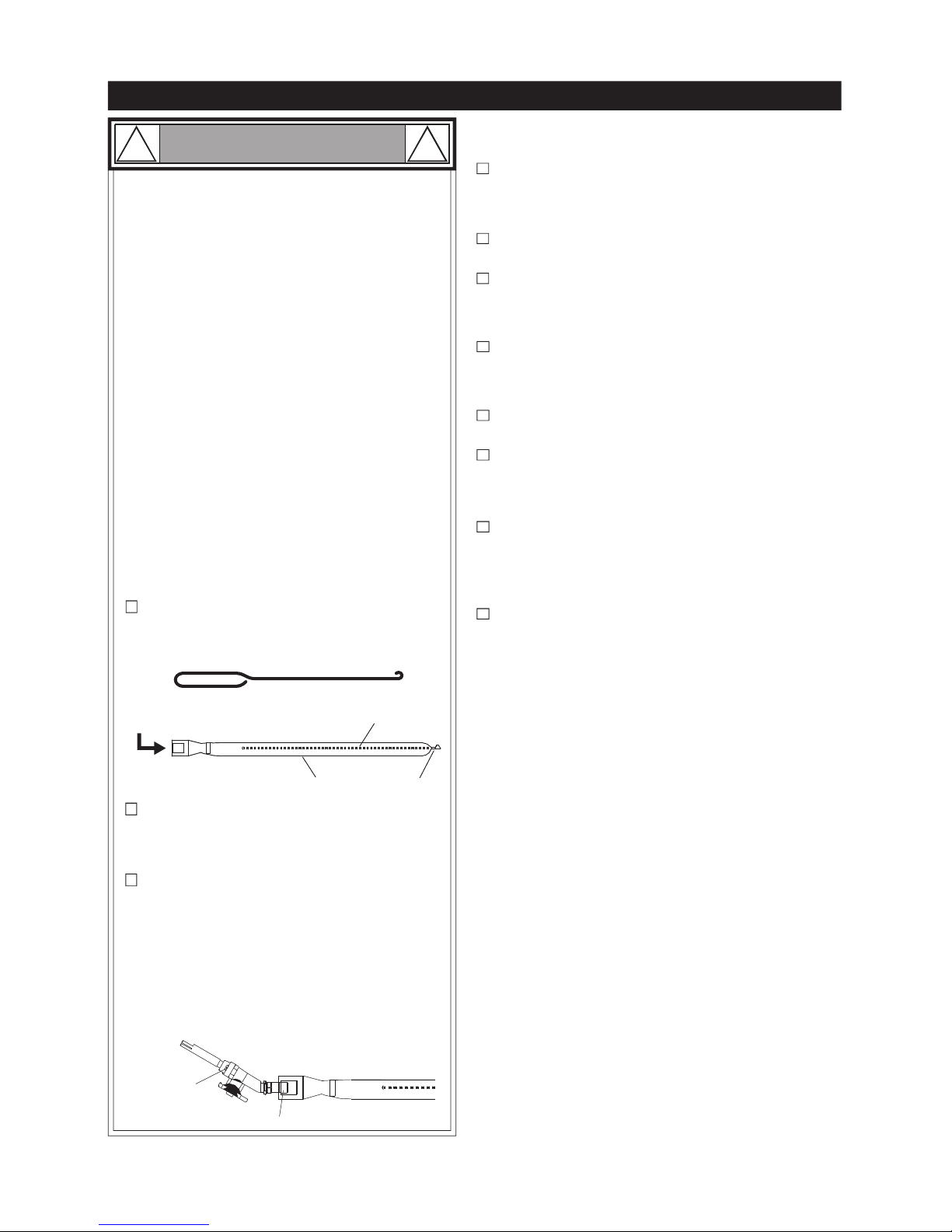
To reduce the chance of FLASHBACK FIRE,
frequent inspection of the burner tube is
recommended at least once a month in summer and
autumn or whenever spiders are active in your area,
and if your barbecue has not been used for an
extended period of time.
Spiders and small insects can spin webs and nest in
the Burner Tubes during transit and warehousing
which can lead to a gas flow obstruction resulting in
a fire in and around the Burner Tubes. This type of
"FLASHBACK FIRE" can cause serious grill damage
and create an unsafe operating condition for the user.
Failure to comply with these instructions could
result in a fire or explosion that could cause serious
bodily injury, death or property damage.
METHOD 3: Use an air hose to force air through
each Burner Tube. The forced air should pass
debris or obstructions through the Burner and out
the Ports.
METHOD 2: Use a bottle brush with a flexible
handle and run the brush through the Burner Tube
and inside the Burner several times to remove any
debris.
For safe operation ensure the Gas Valve Assembly
Orifice is inside the Burner Tube before using your
barbecue. See figure. If the Orifice is not inside the
Burner Tube, lighting the Burner may cause explosion
and / or fire resulting in serious bodily injury and / or
property damage.
1. Remove the screw from the rear of each Burner
using a Phillips Head Screwdriver.
Carefully lift each Burner up and away from the
Gas Valve Orifice.
2.
Check and clean Burner / Venturi Tubes for insects
and insect nests. A clogged tube can lead to a fire
beneath the grill.
3.
Refer to the figure below and perform one of
these 3 cleaning methods:
4.
Tools Required for Assembly include:
protective work gloves
protective eyewear
You will need assistance from another person to
handle the barbecue head and other large, heavy parts.
Open Lid of shipping carton and remove top sheet
of cardboard and / or packing materials. Lay
cardboard sheet on floor and use as a work surface
to protect floor and parts from scratches.
You may slice the carton front corners with a utility
knife to lay open the carton front panel. This allows
you to raise the barbecue head Lid and remove the
components packed inside, making it easier to lift.
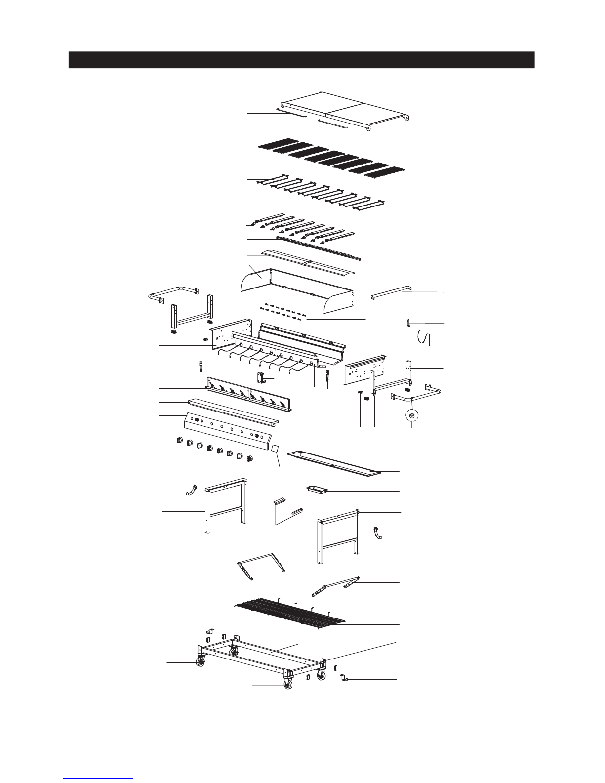
Use the Hardware and Part Diagrams to ensure all
items are included and free of damage.
Do not assemble or operate the barbecue if it appears
damaged. If there are damaged or missing parts
when you unpack the shipping box or you have
questions during the assembly process, call the:
To expedite the assembly process follow these
general guidelines:
NOTE: This appliance is designed to be used with
two Gas cylinders (not included) for 8 burner operation.
A cylinder placed on the right will operate the four
right-side burners. A gas cylinder placed on the left will
operate the four left-side burners.
Never alter or modify any parts sealed by the
manufacturer, unless instructed in this manual.
•
•
•Phillips Head Screwdriver
3
! !
WARNING
METHOD 1: Bend a stiff wire or wire coat hanger
into a small hook as shown and run the hook
through the Burner Tube and inside the Burner
several times to remove debris.
TOCLEAN BURNER TUBE,
INSERT HOOK HERE
Foot
Burner
Burner Port

The following table illustrates a breakdown of the hardware pack. It highlights what parts are used in
the various stages of assembly.
Hardware Pack Parts List for Model CGE06ALP
Phillips Head Screw 1/4"x1/2"
QTY. 28
Part # S112G04081
Hardware Pack Diagram for Model CGE06ALP
PART #PARTDESCRIPTION QTYPURPOSE OF PART
P06021041A Hardware Pack For use in assembly
S112G04061 Phillips Head Screw 1/4"x3/8" Installs Gas Cylinder Holders on the Cart Frame
S112G04081 Phillips Head Screw 1/4"x1/2" Installs Castors on the Cart Frame
Phillips Head Screw 1/4"x3/8"
QTY. 4
Part # S112G04061
Battery AA
QTY. 2
Phillips Head Screw 3/16"x3/8"
QTY. 4
Part # S112G03061
4
S112G03061 Phillips Head Screw 3/16"x3/8" Installs Lid Handles to Lids
S112G04081 Phillips Head Screw 1/4"x1/2" Installs Cart Handles on the Left / Right Bowl
Support Bracket
12
4
16
4
1

5
Parts Diagram for Model CGE06ALP
13
39
36
33
26
27
24
29
25
16
22
12
5
6
4
1
3
17
38
41
37
35
34
32
31
30
21 20 19 18
14
15
11
10
42
8
2
9
7
28
20
43
45
47
17A
23
40
20
44

18 Cart Handle P00205078D 2
KEY PART DESCRIPTION PART # QTY
10 Wind Shield Assembly Y0480002 1
11 Bowl Panel, Rear P0072520JA 1
12 Bowl Panel, Front P0075701JA 1
13 Bowl Panel, Left P0072050JA 1
14 Bowl Panel, Right P0072150JA 1
15 Bowl Support Bracket P01303015D 2
16 Electric Wire Set P02615022A 1
1 Lid, Left P00127045K 1
2 Lid, Right P00128045K 1
3 Lid Handle P00203016M 2
4Cooking Grid P01615037H 8
5 Savor Plate® P01708018E 8
6 Burner P020080234 8
8Burner Bracket P022160184 1
9 Grease Tray Heat Shield P06904044A 2
419 Protective Pad P05518010I
20 Latch Assembly P05517002L 8
21 Hose Bracket P05341001G 2
23 Universal Hose Barb P03901024A 2
26 Control Panel, Upper P02911553I 1
27 Control Panel, Lower – with screen print P02911741I 1
28 Control Knob P03419413R 8
29 Electric Ignitor – 4 port P02502164C 2
30 Grease Tray P02717265B 1
31 Grease Receptacle P02701267B 1
32 Gas Cylinder Hook P04005007C 2
33 Cart Leg, Left P00901014C 1
34 Cart Leg, Right P00902014C 1
35 Cart Frame Bracket P03339001D 2
36 Cart Frame P03335003D 1
37 Cart Seat P04518001A 4
38 Gas Cylinder Holder P04008007C 2
39 Castor – 4" without Brake P05120001D 2
40 Castor – 4" with Brake P05120002D 2
45 Name Plate P00407028C 1
41 Cart Bottom Shelf P01015001D 1
42 Savor Plate® Bracket P033280154 16
43 End Cap P04522001A 4
44 Cart Bracket – grease tray P05330014G 2
7 Gas Collector Box with Electrode P02609002C 8
22 Gas Valve / Manifold Assembly Bracket P03324002H 1
24 Gas Valve / Manifold Assembly, Left Y0060385 1
25 Gas Valve / Manifold Assembly, Right Y0060386 1
Parts List for Model CGE06ALP
6
Gas Valve – without jet P03204101A 8
Jet – 28~30/37 P06517041A 8
17a Lighting Stick Bracket P033280684 1
17 Lighting Stick P05313009B 1
Hardware Pack P06021041A 1
47 Cart Bracket P03304026H 1

Assemble Cart
1
Assembly Instructions
2Install Gas Cylinder Holders to each side of Cart Frame.
(Tighten securely using 4 Phillips Head Screws
1/4"x3/8").
With an assistant, lift Cart out of shipping carton
and place it on the cardboard work surface.
Unfold the Cart Legs and straighten the Cart
Frame Bracket until a click sound is heard.
CAUTION:Do not stand, lean or apply pressure
to the Cart Frame Bracket once assembled.
Install Tank Holders, Castors and Wheels
Install Casters to each side Right Cart Leg.
(Tighten securely using 8 Phillips Head Screws)
Install Cart Brackets to each side Left Cart Leg
using 4 Phillips Head Screws 1/4"x1/2" and attach 8"
Wheels using 2 Wheel Bolts 3/8"x5-5/16", 2 Spring
Washers and 2 Lock Nuts and tighten securely.
Phillips Head Screw 1/4"x3/8"
QTY. 4
Part # S112G04061
Phillips Head Screw 1/4"x1/2"
QTY. 16
Part # S112G04081
7
A
B
B
A
B

4Install Barbecue Bowl
With an assistant, lift and position Barbecue Bowl onto the Cart.
Lock 4 Latches on Barbecue Bowl and Cart.
3Install Lid Handles to Left and Right Lid.
(Tighten securely using 4 Phillips Head Screws 3/16"x3/8")
Install Cart Handles to each Bowl Support Bracket.
(Tighten securely using 12 Phillips Head Screws1/4"x1/2")
Install Handles
Phillips Head Screw 1/4"x1/2"
QTY. 12
Part # S112G04081
Phillips Head Screw 3/16"x3/8"
QTY. 4
Part # S112G03061
Latch
8
A
B
A
B

5Lift and slide the Grease Receptacle out from the Grease Tray
Bracket, from the rear of the Cart.
Unscrew the W ing Bolts on each side of the Grease Tray and
remove the Grease Tray from Bottom Bowl panel.
Reinstall Grease Tray and Grease Receptacle
Attach the Grease Tray to the Bottom Bowl panel using the Wing
bolts and tighten securely.
The Grease Tray is required to be present and centred for your
safety.
Slide the Grease Receptacle over Grease Tray Bracket.
Note: Preassembled Grease Tray and Grease Receptacle
CART REAR VIEW
Wing Bolt
Grease Receptacle
9

6Install Ignitor Batteries
Unscrew Ignitor Cap from Control Panel.
Place supplied AA battery into the Ignitor
Slot with positive pole facing you.
Position the Cap and Spring over the AA
battery and tighten onto Control Panel.
Repeat to install the other AA battery
into the Ignitor Slot.
Failure to read and follow the Use and Care
Instructions could result in a fire or explosion
that could cause serious bodily injury, death or
property damage.
Install Cooking Components
Place the Savor Plates®on lower ledge
above Burners.
Place Cooking Grids on bowl ledge.
With the assistance of another person,
perform this Electrode Check before
proceeding.
This test will ensure that the Spark Electrode
Tips are properly positioned so your barbecue lights
easily and properly.
Be sure all Control Knobs are set to "OFF" and
open the Barbecue Lids.
Have your assistant stand behind to the right
of the barbecue and look toward the front of
the barbecue bowl. Never put your face inside
the Barbecue Head.
Press the Ignitor Cap. You should hear
a "clicking" sound. Your assistant should
see a blue spark within each Gas
Collector Box. If a spark is present the
Electrode Tips are properly positioned.
If no spark is seen, the Spark Gap
needs to be adjusted as follows:
•Using an adjustable wrench, loosen the
Inside Nut until the Gas Collector Box
can be turned upward.
•If the gap between the Spark Electrode Tip
and Receiver is more than 3/16" (4-5 mm)
use long nose pliers to gently squeeze
the Gas Collector Box to narrow gap.
•Return the Gas Collector Box to its
original position, secure the Inside Nut
and try the Electrode Check again. If no
"clicking" sound is heard:
8
7
Final Assembly Step
When you have finished assembling your
barbecue be sure that all screws are tightened
for safe operation of your barbecue.
AA Battery is installed backwards.
-
Electric wires may be loose. Remove
the AA Battery and inspect the Ignitor
Junction Box found behind the Control
Panel and reconnect any loose wires.
-
Spark Electrode Tip
Spark Gap
3/16" (4-5 mm)
Spark Receiver
Gas Collector Box
Inside Nut
Spring
+
-
AA Battery
Ignitor Cap
Ignitor Slot
Cooking Grids
Savor Plates®
10
! !
WARNING

CORRECT GAS CYLINDER USE
The gas cylinder supply system must be arranged for
vapour withdrawal.
This model barbecue is designed for use with two gas
cylinders, not included with barbecue. Never connect
your gas barbecue to an gas cylinder that exceeds
this capacity.
Acylinder of approximately 12 inches (300 mm)
diameter by 18-1/2 inches (470 mm) high is the maximum
size gas cylinder to use.
The gas cylinder used must have a collar to protect
the cylinder valve.
Never connect an unregulated gas cylinder to your
gas barbecue. Check the gas type label for correct
operating pressure. Only use the regulator and hose
assembly supplied with your gas barbecue. Replacement
regulators and hose assemblies must be those specified
by the Manufacturer.
Always keep gas cylinder in upright position.
Do not subject the gas cylinder to excessive heat.
Gas cylinders must be stored outdoors in a
well-ventilated area and out of the reach of children.
Never store an gas cylinder indoors. If you store
your gas barbecue in the garage always disconnect the
gas cylinder first and store it safely outside.
The regulator and hose assembly must be inspected
before each use of the barbecue. If there is excessive
abrasion or wear or if the hose is cut, it must be replaced
prior to using the appliance again.
Disconnected gas cylinders must not be stored in
a building, garage or any other enclosed area.
Never light your gas barbecue with the lid closed or
before checking to ensure the burner tubes are fully
seated over the gas valve orifices.
Never allow children to operate your barbecue. Do not
allow children or pets to play near your barbecue.
Use of alcohol or drugs may impair the ability to
assemble and operate the appliance.
Use your barbecue on a level, stable surface in an
area clear of combustible materials.
Do not move the appliance when in use.
Do not leave barbecue unattended when in use.
Allow the barbecue to cool before moving or storing.
Cover your barbecue when not in use.
Do not use your barbecue as a heater.
This barbecue is not intended to be installed in or on
recreational vehicles and / or boats.
Keep fire extinguisher readily accessible. In the event
of a oil / grease fire, do not attempt to extinguish with
water. Use an extinguisher or smother with dirt, sand
or baking soda.
•Use your barbecue outdoors, at least 3 feet
(900 mm) away from any wall or surface. Use
your barbecue at least 3 feet (900 mm) away
from combustible objects that can melt or catch
fire (such as vinyl or wood siding, fences and
overhangs) or sources of ignition including pilot
lights on water heaters and live electrical appliances.
Never obstruct the flow of ventilation air around
your gas barbecue housing.
•
Do not store a spare gas cylinder under or near
this appliance.
•
Never use your gas barbecue in a garage, porch,
shed, breezeway or any other enclosed area.
•
11
! !
WARNING
Use and Care Instructions

How to Leak Test your Gas Cylinder
For your safety:
Gas Connections
CAUTION:
When the appliance is not in use, the gas
must be turned off at the cylinders.
Never operate this appliance without a regulator.
Use gas hose / connections / regulator compying with
local regulation.
If the gas hose has not been factory fitted, then
connect to the manifold inlet as shown.
Ensure connection is secure.
Gas hose must not exceed 1.5 m in length.
Gas type: I 3+ (28~30/37)
Butane 28-30 millibars.
Propane 37 millibars.
Check for gas leaks. Refer next page:
"Checking for
Gas Leaks"
.
Hang your gas cylinders on the top Cylinder Hooks.
The ring foot of the gas cylinders will rest on the Cylinder
Holder or it can be placed on the ground.
The following gas cylinder sizes are recommended:
Butane >7 kg. Propane >6 kg.
All leak tests must be repeated each time your gas
cylinder is exchanged of refilled.
Do not use an open flame to check for gas leaks.
Your barbecue must be leak tested outdoors in a well
ventilated area, away from ignition sources such as gas
fired or electrical appliances. During the leak test, keep
your barbecue away from open flames or sparks.
Do not use household cleaning agents. Damage to gas
assembly components can result.
Before using this gas appliance read all instructions
and perform all gas leak-check procedures even if the
product was pre-assembled by the retailer or
manufacturer.
When changing a gas cylinder, perform this procedure
away from any source of ignition.
When checking for gas, do not smoke.
If growing bubbles appear do not use or move the LP
Gas cylinder. Contact an LP Gas Supplier or your fire
department!
Use a clean paintbrush and a 50/50 mild soap and
water solution.
Brush soapy solution onto gas cylinder in the areas
indicated by the arrows. See diagram.
If growing bubbles appear do not use or move the
gas cylinder. Call a Gas Supplier or your Fire
Department.
Inspect the valve connection port and regulator
assembly for damage or debris. Remove any debris.
Never use damaged or plugged equipment.
Open the cylinder valve fully (counterclockwise) and
use a soapy water solution to check all connections
for leaks before attempting to light your barbecue.
See
"Checking for Gas Leaks"
. If a leak is found,
turn the cylinder valve off and do not use your
barbecue until the leak is repaired.
Connect the regulator assembly to the cylinder valve
and tighten securely.
Turn all Burner Valves to the OFF position.
Connect Regulator with Hose to your Gas Cylinder
12
Use and Care Instructions
! !
WARNING
! !
WARNING
0.95

Check all connections for Gas Leaks
Never test for leaks with a flame. Prior to first use,
at the beginning of each season, or every time
your gas cylinder is changed, you must check for
gas leaks. Follow these three steps:
Make a soap solution by mixing one part liquid
detergent and one part water.
Turn the barbecue Control Knobs to the full OFF
position, then turn the gas ON at source.
Apply the soap solution to all gas connections
indicated by the arrows. See diagram. If bubbles
appear in the soap solution the connections are not
properly sealed. Check each fitting and tighten or
repair as necessary.
CAUTION: Always open both left and right Lids
as shown before lighting your barbecue.
If you have a gas leak that cannot be repaired by
tightening, turn off the gas at the source, disconnect
fuel line from your barbecue and call 0416 2744 500
or your gas supplier for repair assistance.
Never disconnect the gas regulator or any gas fitting
while your barbecue is lit. A lit barbecue can ignite
leaking gas and cause a fire or explosion which could
result in property damage, personal injury or death.
Disconnecting A Gas Cylinder From Your Barbecue
Make sure the Burner Valves and Gas cylinder valve
are off. (Turn clockwise to close.)
Detach the hose and regulator assembly from the
gas cylinder valve. Do not disconnect hose fom the
appliance.
Gas Valve / Manifold Assembly
LP Gas Cylinder
Regulator
with Hose
Gas Hose
Lock Castors while
your barbecue is in use
13
! !
WARNING
Use and Care Instructions

Barbecue Lighting Instructions
Never
lean over the barbecue cooking area while lighting
your gas barbecue. Keep your face and body a safe
distance (at least 18 inches / 450 mm) from the Lighting
Hole or Burners when lighting your barbecue by match.
Manually Lighting Your Barbecue By Match
NOTE:
This gas barbecue is designed to be used with two
gas cylinders (not included) for 8 burner operation.
A cylinder placed on the right will operate the four right-side
burners. A cylinder placed on the left will operate the four
left-side burners.
Immediately press the right-side Electric Ignitor for
3-4 seconds to light the Burner.
If ignition does not occur in 5 seconds, turn the
burner Control(s) off, wait 5 minutes, and repeat
the lighting procedure. If ignition does not occur
in 5 seconds, turn the burner Control(s) and gas
source OFF and conduct a leak test of ALL gas
connections and gas sources as explained in the
Use and Care section of this manual. If no leaks
are detected, wait 5 minutes for any gas to clear
and repeat the lighting procedure.
Once one Burner is lit, the adjacent Burner can be lit
by turning its Control Knob to HIGH.
To light the four left-side burners repeat step 7 and 8
then press the left-side Electric Ignitor.
10.
11.
12.
9.
6.
Before each use, check all hoses for cracks, nicks,
cuts, burns or abrasions. If a hose is damaged in any
way, do not use your barbecue before replacing the
hose with an authorised part from the Parts List. Also
make sure all gas supply connections are securely
tightened.
For optimum performance this barbecue should be
used only when outdoor temperatures are 60¼F (16¼C)
or above.
Familiarise yourself with the safety and Use and Care
instructions in this manual. Do not smoke while
lighting barbecue or checking gas supply connections.
Be sure each gas cylinder is filled and lock Castors
to prevent movement during barbecue operation.
Open the left and right Lids before lighting the barbecue.
Check that the end of each Burner Tube is properly
located over each Valve Orifice.
1.
5.
4.
3.
2.
Failure to replace a faulty hose, secure gas supply
connections or to open the Lid before proceeding to the
Lighting Procedures could result in a fire or explosion that
could cause serious bodily injury, death, or property damage.
Set all Control Knobs to OFF and open the right-side
cylinder valve.
To light the four right-side burners, push and turn the
fourth Control Knob from the right to HIGH.
8.
7.
NOTE:
Gas cylinder must be connected to the right side.
To light your gas barbecue by match, insert a match into
the Lighting Stick and follow steps 1 through 6 of the
Barbecue Lighting Instructions. Then, light the match and
place Lighting Stick through the Lighting Hole on the right
side of the barbecue as shown below. Turn the Control
Knob nearest the open cylinder to the HIGH setting to
release gas. The Burner should light immediately. Cross
light unlit burners sequentially to the left.
NOTE:
To light the far four left burners, ensure gas cylinder
is attached to the left side.
BurnerControl Knobson ControlPanel
BurnerControl Knobs on Control Panel
Left 4 Burners are controlled
by left gas cylinder Right 4 Burners are controlled
by right gas cylinder
PRESS
HIGH
The fourth middle Control Knobs
Lighting Hole
Match
Lighting Stick
Open gas cylinder
14
! !
WARNING
! !
WARNING
Use and Care Instructions

Troubleshooting
If the barbecue fails to light:
Turn gas off at source and turn Control Knobs to
OFF. Wait at least five minutes for gas to clear,
then retry.
1.
If your barbecue still fails to light, check gas supply
and connections.
2.
Repeat lighting procedure. If your barbecue still
fails to operate, turn the gas off at source, turn the
Control Knobs to OFF, then check the following:
3.
If an obstruction is suspected in Gas Valves or
Manifold, call the Barbecue Information Centre.
Obstruction in gas line
Correction: Remove fuel line from barbecue.
Do not smoke! Open gas supply for one second to
clear any obstruction from fuel line. Close off gas
supply at source and reconnect fuel line to barbecue.
Plugged Orifice
Correction: Remove the screw from the rear of
each Burner using a Phillips Head Screwdriver.
Remove the Orifice from gas valve and gently clear
any obstruction with a fine wire. Then reinstall all
Orifices, Burners, Screw and cookingcomponents.
Obstruction in Burner Tubes
Correction: Follow the Burner Tube cleaning
procedure on page 18 of this Operator's Manual.
Misalignment of Burner Tubes over Orifices
Correction: Reposition Burner Tubes over Orifices.
Misalignment of Ignitor on Burner
Correction: Check for proper position of the
Electrode Tip as shown in step 7 page 11. The gap
between the Spark Electrode Tip and Spark
Receiver should be approximately 3/16" (4 - 5 mm).
Adjust if necessary. With the gas supply closed and
all Control Knobs set to OFF press the Electric
Ignitor cap and check for the presence of a spark
at the Electrode.
Disconnected Electric Wires
Correction: Inspect the Ignitor Junction Box found
behind the Control Panel. Connect loose Electric
wires to Junction Box and try to light the barbecue.
Weak AA battery
Correction: Unscrew the Ignitor Cap and replace
the battery.
If the barbecue still does not light you may need to
purge air from the gas line.
Note: This procedure should be done every time a
new gas cylinder is connected to your barbecue.
To purge air from your gas line:
Turn Control Knobs to the OFF position.
Turn off the gas at the cylinder valve.
Disconnect regulator from Gas cylinder.
Let unit stand 5 minutes to allow air to purge.
Reconnect regulator to the Gas cylinder.
Open the Barbecue Lids.
Turn cylinder valve on SLOWLY 1/4 of a turn.
Push and turn the middle Control Knob furthest
from open cylinder to HIGH.
Press Electric Ignitor for 3 - 4 seconds to light
the burners.
Failure to comply with these instructions may
result in a hazardous situation which, if not
avoided, may result in injury.
Keep barbecue area clear and free from
combustible materials, petrol and other
flammable vapours and liquids.
•
Do not obstruct the flow of air for combustion
and ventilation.
•
Visually check burner flames occasionally to
ensure proper flame pattern as shown below.
•
Should a FLASHBACK fire occur in or around
the Burner Tubes, follow the instructions below.
Failure to comply with these instructions could
result in a fire or explosion that could cause
serious bodily injury, death, or property damage.
Shut off gas supply to the gas barbecue.
•
Turn the Control Knobs to OFF position.
•
Open the Barbecue Lid.
•
Put out any flame with an extinguisher or fire
blanket.
•
Once the barbecue has cooled down, clean
the Burner Tubes and Burners according to
the cleaning instructions in this Operator's
Manual.
•
MAGNIFIED VIEW OF
BURNER FLAME
THROUGH LIGHTING
HOLE
15
! !
WARNING
! !
CAUTION
Use and Care Instructions

5. Fold the Cart Legs onto Cart Frame. See Fig.1.
Proper care and maintenance will keep your barbecue in
top operating condition and prolong its life. Follow these
cleaning procedures on a timely basis and your barbecue will
stay clean and operate with minimum effort.
CAUTION: Be sure your barbecue is OFF and cool before
cleaning. Use protective gloves when handling hot components.
Cleaning Exterior Stainless Steel Surfaces:
Transporting or Storing your barbecue:
2. Lock barbecue Castors.
1. Turn off gas control valves and gas cylinder valve.
Disconnect gas hose from gas cylinder. Protect
connections against damage. DO NOT remove gas
hose from appliance.
3. Remove gas cylinder and Grease Tray from your
barbecue. Place Grease Tray on Lower Grease Tray
Bracket. See Fig.1.
4. Loosen 4 Latches on Barbecue Bowl and Cart. With
an assistant, lift and position Barbecue Bowl on a
cardboard surface.
6. With an assistant, lift and position Barbecue Bowl onto
the folded Cart. See Fig.1.
Lock 4 Latches on Barbecue Bowl and Cart. See Fig.2.
7. Be sure barbecue is secured tightly and covered when
being transported.
8. Storage – Outdoors: Store in a dry covered area.
A cover is recommended.
Storage – Indoors: DO NOT store gas cylinders indoors.
Fig. 2
Fig. 1
Before initial use, and periodically, wash your Cooking
Grids in a mild soap and warm water solution. You
can use a wash cloth or vegetable brush to clean your
Cooking Grids.
Cleaning The Cooking Grids
Cleaning The Savor Plates®
Periodically you should wash the Savor Plates®in a
soap and warm water solution. Use a vegetable brush
to remove stubborn burnt-on cooking residue. Dry the
Savor Plates®thoroughly before you reinstall them
into the cooking bowl.
Cleaning The Grease Tray and Receptacle
To reduce the chance of fire, the Grease Draining Tray
and Grease Receptacle (some models) should be
visually inspected before each use. Remove any
grease and wash Grease Tray and Receptacle with a
mild soap and warm water solution.
Cleaning the Inside of the Barbecue Lid
Grease can have a tendency to build up on the inside
of the Barbecue Lid and could drip onto deck or patio
when the lid is opened. Visually inspect the inside of
the Barbecue Lid before each use. Remove any grease
and wash with a mild soap and warm water solution.
Annual Cleaning of The Barbecue Interior
Burning-off excess food after every cookout will keep
it ready for instant use. However,at least every 3
months you must give the entire barbecue a thorough
cleaning to minimise your risk of grease fire and keep
the barbecue in top shape. Follow these steps:
Turn all Burner Valves to the full OFF position.1.
Turn the gas cylinder valve to the full OFF position.
2.
Disconnect the regulator from the gas cylinder. Inspect
the hose with regulator assembly for cracking, cuts or
any other damage, and replace as neccessary. Refer
to the Parts List in this Operator's Manual.
3.
Remove and clean the Savor Plates , Cooking Grids
and Burners.
4.
Cover each Gas Valve Orifice with aluminum foil.
5.
Brush the inside and bottom of the barbecue with a
fibre pad or nylon brush and wash with a mild soap
and warm water solution. Rinse thoroughly and let dry.
6.
Remove aluminum foil from Orifices and check each
Orifice for obstruction.
7.
Check each Spark Electrode, adjusting as needed.
The space between the Spark Electrode Tip and Spark
Receiver should be approximately 3/16" (4 - 5 mm).
8.
Replace the Burners and adjust the Gas Collector
Box. The edge of the collector box should be
overlapping the Burner Port.
9.
Replace Savor Plates®and Cooking Grids.
10.
11. Reconnect the gas source and observe the Burner
flame for correct operation.
Before initial use, and periodically thereafter, we
suggest you wash your barbecue using a mild soap
and warm water solution. You can use a wash cloth
or sponge for this process. Do not use a stiff wire or
brass brush. These will scratch stainless steel and
chip painted surfaces (varies by model) during the
cleaning process.
Cleaning Exterior Surfaces:
Weathering and extreme heat can cause exterior
stainless steel surfaces to turn tan in color.
Machine oils used in the manufacturing process
of stainless steel can also cause this tanning
color. After removing any protective PVC film from
the Control Panel, use a Stainless Steel Cleaner to
polish the stainless steel surfaces of your barbecue.
Never use abrasive cleaners or scrubbers because
they will scratch and damage your barbecue. Follow
these steps for the best results.
Turn the gas cylinder valve (clockwise) to the full
OFF position. Disconnect the regulator and hose
assembly from gas cylinder. Cover exposed gas
fitting with aluminum foil.
1.
Remove dirt or grease using a soft cloth and
polish stainless surfaces. Wipe with a soft cloth.
2.
Remove aluminum foil from exposed gas fitting
and allow barbecue to air dry before attaching the
regulator and hose to your gas cylinder.
3.
16
Cleaning and Maintenance

Figure 1
CLEANING THE BURNER TUBES AND BURNER PORTS
Turn all Burner Valves to the full OFF position.
Turn the Gas cylinder valve to the full OFF position.
Detach the Gas regulator assembly from your
gas barbecue.
Remove the screw from the rear of each Burner
using a Phillips Head Screwdriver.
Carefully lift each Burner up and away from the Gas
Valve Orifice.
Check and clean burner / venturi tubes for insects and
insect nests. A clogged tube can lead to a fire beneath
the barbecue.
Refer to
Figure 1
and perform one of these three
cleaning methods:
Regardless of which Burner cleaning procedure you use, we
recommend you also complete the following steps to help
prolong Burner life.
1. Use a fibre pad or nylon brush to clean the entire outer
surface of each Burner until free of food residue and dirt.
2. Clean any clogged ports with a stiff wire, such as an
open paper clip.
3. Inspect each Burner for damage (cracks or holes) and if
such damage is found, order and install a new Burner.
After installation, checkto ensure that the Gas Valve
Orifices are correctly placed inside the ends of the Burner
Tubes. Also check the position of your Spark Electrode.
For safe operation ensure the Gas Valve Assembly
Orifice is inside the Burner Tube before using your
barbecue. See figure. If the Orifice is not inside the
Burner Tube, lighting the Burner may cause
explosion and / or fire resulting in serious bodliy injury
and / or property damage.
METHOD 1: Bend a stiff wire or wire coat hanger
into a small hook as shown and run the hook through
the Burner Tube and inside the Burner several times
to remove debris.
METHOD 2: Use a bottle brush with a flexible handle
and run the brush through the Burner Tube and
inside the Burner several times to remove any debris.
METHOD 3: Use an air hose to force air through
each Burner Tube. The forced air should pass debris
or obstructions through the Burner and out the Ports.
TO CLEAN BURNER TUBE,
INSERT HOOK HERE
1.
2.
3.
4.
5.
6.
7.
8.
To reduce the chance of
FLASHBACK FIRE
you must
clean the Burner Tubes as follows at least once a month
in summer and autumn or whenever spiders are active in
your area, and if your barbecue has not been used
for an extended period of time.
Remove the Cooking Grids, Savor Plates¨and
Grease Trays from your barbecue.
Burner Port
Burner Foot
Gas Valve
Orifice
17
! !
WARNING
Cleaning the Burner Tubes and Burner Ports

18
Question:
Are the serial and model numbers of my barbecue
listed somewhere for reference?
Answer:
The serial and model numbers are listed on a silver data
label placed on the barbecue. Depending on the barbecue
model the silver data label will be located on the left or right
side bowl panel underneath the side shelf, underneath
the right side of the control panel, outside left or right of
control panel or on the back of the barbecue cabinet.
Question:
My
barbecue
will not light properly. Why?
Answer:
Always light the main Burner furthest from the fuel
source first. This will draw gas across the manifold
helping prevent air pockets which obstruct gas flow and
prevent proper grill lighting. Also try this procedure:
Question:
Where do I use my barbecue for safer operation and better
performance?
Question:
If my ignitor or battery is not working how can I light
my barbecue? And - Why would I need the silver
lighting stick that hangs from the side of my barbecue?
Answer:
If your ignition fails to work or your battery needs
replacing, you can light your barbecue through the
Lighting Hole on the side of the barbecue bowl using the
Manual Lighting Stick that hangs from the side of your
barbecue. The Lighting Stick is designed to hold a match
and allows you to safely insert a match through the
Lighting Hole without getting close to the Burner. Never
remove the Cooking Grids or Savor Plates¨and attempt
to light the barbecue from above. To light your gas
barbecue manually, insert a match into the Manual
Lighting Stick and follow steps 1 through 6 of the Basic
Lighting Procedures. Then, light the match and place it
through the Lighting Hole on the right side of the barbecue
(location of hole varies by barbecue model). Turn the
nearest main Burner Control Knob to the High setting to
release gas. The Burner should light immediately.
Answer:
Strong winds and low temperatures can affect the heating
and performance of your gas barbecue so factor in these
elements when positioning your barbecue outdoors for
cooking.
Use your barbecue at least 3 feet away from any wall or
surface.
Use your barbecue at least
3 feet away
from combustible
objects that can melt or catch fire (such as vinyl or wood
siding, fences and overhangs) or sources of ignition including
pilot lights on water heaters and live electrical appliances.
Never
use your gas barbecue in a garage, porch, shed,
breezeway or any other enclosed area.
Never
obstruct the flow of ventilation air around your gas
barbecue housing.
Repeat lighting procedure.
If your barbecue still fails to operate, turn the gas off
at source, turn the Control Knobs to OFF and refer to
theTroubleshooting Section for more tips, or call the
Barbecue Information Centre.
3.
If your barbecue still fails to light, check gas supply
and connections.
2.
Turn gas off at source and turn Control Knobs OFF.
Wait at least 5 minutes for gas to clear, then retry.
1.
Frequently Asked Questions (FAQs)

19
Question:
What causes barbecue parts to rust and what affect
does it have on my barbecue?
Rusting is a natural oxidation process and may appear
on cast-iron and steel parts. Rust will not affect the short
term performance of your barbecue.
To slow the rusting process on steel Cooking Grids
(select models) we recommend greasing the Cooking
Grids before and after each cookout. Use a brush to apply
a thin layer of cooking oil or vegetable shortening onto
each Cooking Grid. We do not suggest spray type oils
unless they are specified for high-temperature cooking.
Be sure to coat the entire cooking surface including edges
and any areas with chipped porcelain.
Answer:
Question:
Which is a better cooking surface to cook on;
porcelain coated steel / cast-iron cooking grids or
stainless steel grids?
NOTE: Further information may be obtained at
www.grandhall.eu/service/faqs/
Answer:
They all have their advantages. For traditional grilling
and searing meats, cast-iron or steel grids offer better
heat conductivity. To protect against the natural rusting
process, steel or cast-iron cooking grids offer a porcelain
finish which requires routine maintenance to keep the
grids well seasoned.
Stainless steel is popular with those who prefer less
maintenance.
A new innovative solution is available on select models
called Stainless Clad Therma-Core®. This Cooking Grid
combines a heat conducting steel core with an
easy-to-clean stainless outer shell.
Frequently Asked Questions (FAQs)

Grand Hall Enterprise Co., Ltd. will warrant to the ORIGINAL PURCHASER of this gas grill that it will be free
of defects in material and workmanship for set periods below from the date of purchase when used under normal
outdoor use and correct assembly:
Full Warranty on Barbecue – 1 year
(except for paint loss, rusting and ignitor battery)
Stainless Steel Parts and Tube Burners – 5 years no rust through
Cooking Grids – 3 years no rust through
Savor Plates®– 2 years no rust through
Grand Hall will require reasonable proof of your date of purchase. Therefore, you should send in the owner
registration card. Save your receipt in case it is required as proof of purchase.
Grand Hall Limited Warranty
This Limited warranty is limited to repair or replacement of parts, at Grand Hall’s option that proved to be
defective under normal use and service.
Grand Hall may require the return of defective parts for examination before issuing replacement parts or
repairs. If you are required to return defective parts, transportation charges must be prepaid.
Upon examination and to Grand Hall’s satisfaction, if the original part is proven defective Grand Hall may
approve your claim and elect to replace such parts without charge. You are responsible for shipping charges of
such replacement parts.
This Warranty does not cover any failures or operating difficulties due to accident, abuse, misuse, alteration,
misapplication, vandalism, improper installation, maintenance or service, damages caused by flashback fires or
grease fires, as set out in this Operator’s Manual.
Deterioration or damage due to severe weather conditions such as hail, hurricane, earthquakes, tsunami,
tornadoes, Acts of God or terrorism, discoloration due to exposure to chemicals either directly or in the atmosphere,
is not covered by this Limited Warranty.
No returns will be accepted without prior authorization from Grand Hall –
www.grandhall.eu/service/registration/
Warranty Restrictions
•
•This grill is safety certified for use only in the country where purchased. Modification
for use in any other location is a safety hazard and will void the warranty.
This warranty gives you specific legal rights, and you may also have other rights
which vary from state to state.
Manufacturer:
Grand Hall Enterprise Co., Ltd.
9th Fl., No.298, Rueiguang Rd., Neihu,
Taipei, Taiwan (114)
Table of contents
Other GrandCafe Grill manuals
Popular Grill manuals by other brands

oklahoma joes
oklahoma joes Longhorn Smoker 06201348 Assembly instructions

Dansons Group
Dansons Group Louisiana Grills LG900C2 Assembly and operation

Dyna-Glo
Dyna-Glo DGN405DNC manual

anko
anko SK1 user manual

Louisiana Grills
Louisiana Grills CS 680 owner's manual

Suwanee
Suwanee SG-304-16/SB owner's manual