GrandCafe CGI08ALP User manual

Manual#P80170008B-Date:2007/12/04
Grill Island
ModelCGI08ALP
OPERATOR'SMANUAL
Ÿ
Ÿ
NOTETOASSEMBLER/INSTALLER:
Leavethismanualwiththeconsumer.
NOTETOCONSUMER:
Keepthismanualforfuturereference.
RECORDYOURSERIAL# __________________
(seesilverCSAlabelonmainbodyofgrill)
IMPORTANT:
Ÿ
NOTE:CompleteIsland Kit requires3boxes
Failuretocomplywiththeseinstructionscould
resultinafireorexplosionthatcouldcause
seriousbodilyinjury,deathorpropertydamage.
Whetherthisgrill wasassembled byyouor
someoneelse,youmustreadthisentiremanual
beforeusing yourgrilltoensurethe grillis
properlyassembled,installedandmaintained.
Use yourgrill atleast3feetaway fromany
wall orsurface. Useyourgrill atleast 3feet
awayfromcombustibleobjectsthatcan meltor
catchfiresuchasvinylorwood siding,fences
and overhangsorsourcesof ignition including
pilotlightson waterheatersand liveelectrical
appliances.
THISGASAPPLIANCEISDESIGNEDFOROUT-
DOORUSEONLY.
Never useyourgasgrillinagarage,porch,
shed,breezewayoranyotherenclosedarea.
Never obstructtheflowofventilation air
around yourgasgrill housing.
Never disconnectthe gasregulatororanygas
fitting while yourgrillislit.Alitgrill canignite
leakinggasand causeafireorexplosionwhich
couldresultinpropertydamage,personalinjury
ordeath.
Ÿ
Ÿ
Ÿ
Ÿ
Ÿ
Ÿ
WARNING
! !
Ÿ
FREEHELP
FROMTHEGRILLEXPERTS
Donotreturntothestore. AtGrandHallwe're
theexpertson thisproduct andtrained tohelp
youwith:
Assemblyquestions
Grilloperation
Replacementofdamagedormissingparts
Ÿ
Ÿ
Ÿvisit www.grandhall.com orcall:
1-800-761-5456
Monday-Friday8:00am-4:30pmCST

2
TableofContents
PrimarySafetyWarnings...........................1-3
Pre-AssemblyInstructions..............................3
PartDiagramsandLists........................4-13
AssemblyInstructions.............................14-20
Use&CareInstructions:
•GasSafetyand LeakTests...........21-23
•Lighting Instructions............................24-25
•Troubleshooting.........................................25
•Rotisserie Instruction...........................26-28
•FaucetOperation....................................29
•RefrigeratorInstruction.............................30
•Cleaning andMaintenance................31-32
•CookingGuide...................................A1-A6
•FrequentlyAsked Questions............A7-A8
WarrantyTerms...........................BackCover
WARNING
! !
•
Keepgas regulatorhose awayfromhotgrill
surfaces and dripping grease.Avoidunneces-
sarytwisting ofhose.Visuallyinspecthose
priortoeach use forcuts,cracks,excessive
wearorotherdamage.Ifthehose appears
damageddo notuse thegas grill.Call Grand
Hall at1-800-761-5456 foracertifiedreplace-
menthose.
CaliforniaProposition65
Combustionbyproductsproducedwhenusing
thisproductcontainchemicalsknowntothe
StateofCaliforniatocausecancer,birthde-
fects,orotherreproductiveharm.
Brass componentson thegrill,suchashose
fittings, propane cylindervalves(soldsepa-
rately) and burnervalvestems, containlead
whichisknowntothe StateofCalifornia to
causecancer,birthdefects,orotherreproduc-
tiveharm.
Neverusecharcoalorlighterfluidinthisgas
grill.Failuretocomplywiththeseinstructions
couldresultinagreasefireorexplosion that
couldcauseseriousbodilyinjury,deathor
propertydamage.
TheGreaseDrainingTrayandGreaseRecep-
taclemustbevisuallyinspectedbeforeeach
grilluse.RemoveanygreaseandwashGrease
DrainingTrayandGreaseReceptacle witha
mildsoapandwarmwatersolution.Failureto
complywith these instructionscould re-
sultinagreasefireorexplosionthatcould
causeseriousbodilyinjury,deathorprop-
ertydamage.
LPGmodelsmustbeusedwithLiquid
PropaneGas and the regulatorassembly
supplied.NaturalGas modelsmustbe used
withNaturalGasonly.Anyattempttoconvert
thegrillfromonefueltypetoanotheris
hazardous andmustbeperformed bya
qualifiedgastechnicianonly,usingaNG
ConversionKitpurchasedfromGrand Hall.
•
•
•
•
Donotstoreoruse gasolineorother
flammableliquidsorvaporsinthe
vicinityofthisoranyotherappli-
ances.
AnLPcylindernotconnectedforuse
shall notbestoredinthevicinityof
thisoranyotherappliance.
DANGER
!!
1.
2
3.
4.
Ifyousmell gas:
Shutoff gas totheappliance.
Extinguishanyopenflame.
Openlid.
Ifodorcontinues,keepawayfrom
theappliance andimmediatelycall
yourgas supplieroryourfire
department.
1.
2.
WARNING
! !

3
Pre-AssemblyInstructionsForYourSafety
Toexpeditethe assemblyprocess followthese
generalguidelines:
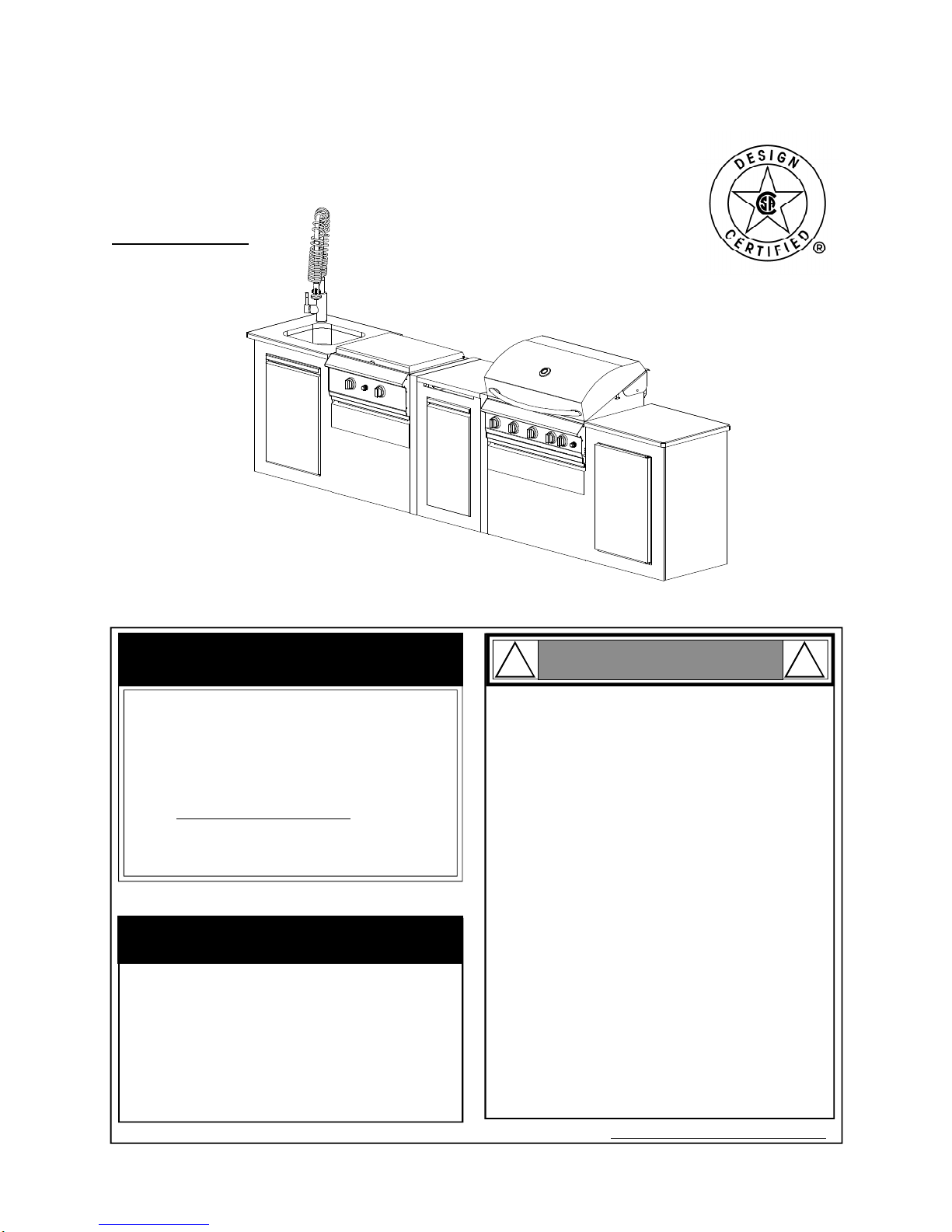
GrillInformationCenter 1-800-761-5456
8am-4:30pmCST,MondaythroughFriday
Spidersand small insectscanspinwebsand
nestinthegrill BurnerTubes during transitand
warehousing which canleadtoagas flow
obstruction resulting inafireinand around the
BurnerTubes.Thistypeof"FLASHBACK FIRE"
cancause seriousgrill damageand createan
unsafeoperating condition fortheuser.
Toreduce thechance ofFLASHBACK
FIREyou mustcleantheBurner Tubes
as followsbefore initialuse. Alsodo this
atleastonceamonthinsummerand fall or
wheneverspidersareactiveinyourarea,and if
yourgrill has notbeenusedforanextended
period oftime.
WARNING
! !
Failuretocomplywiththeseinstructionsmay
resultinahazardoussituationwhich,ifnot
avoided,mayresultininjury.
Forsafeoperation ensuretheGas ValveAssem-
blyOrificeisinsidetheBurnerTubebeforeusing
yourgrill.See figure.IftheOrificeisnotinside
theBurnerTube,lighting theBurnermaycause
explosion and/orfireresulting inseriousbodily
injuryand/orpropertydamage.
METHOD 1:Bend astiff wireorwirecoat
hangerintoasmall hook as shownand run
thehook through theBurnerTubeand inside
theBurnerseveraltimes toremovedebris.
METHOD 2:Use abottlebrushwithaflexible
handleand run thebrushthrough theBurner
Tubeand insidetheBurnerseveraltimes to
removeanydebris.
METHOD 3:Use anairhose toforceair
through each BurnerTube.Theforcedair
shouldpass debrisorobstructionsthrough
theBurnerand outthePorts.
TOCLEANBURNERTUBE,INSERTHOOK
HERE
BurnerTube
9
Grill Installation Codes
Theinstallation mustconformwithlocalcodesor,inthe
absenceoflocalcodes,withthe NationalFuelGas
Code,ANSIZ223.1/NFPA54,Storage and Handling of
Liquefied PetroleumGases,ANSI/NFPA58,NaturalGas
and Propane Installation Code,CSA B149.1, Propane
Storage and Handling Code,B149.2.
Orifice BurnerTube
GasValveAssembly
Carefullylift eachBurnerupandaway fromthe
GasValveOrifice.
CheckandcleanBurner/VenturiTubesfor
insectsand insectnests.Acloggedtubecan
leadtoafirebeneaththegrill.
Refertothefigurebelowand performoneof
these 3cleaning methods:
Remove thescrewsfromtherearofeachMain
BurnerusingaPhillipsHeadScrewdriver.
1.
2.
3.
4.
BurnerPort Foot
WARNING
! !
Thisappliance,when installed,mustbe electri-
callygrounded inaccordancewithlocalcodes
or,inthe absenceoflocalcodes,withthe
National Electrical Code,ANSI/NFPA 70, orthe
Canadian Electrical Code,CSA C22.1.
Keep anyelectricalsupplycordand the fuel
supplyhoseawayfromanyheated surfaces.
•
•
CAUTION !
Whenusing electricalappliances,basic
safetyprecautionsshould always beused.
!
1.
WARNING
! !
DonotstorespareLPcylinder
within10feet(3m)ofthisappliance.
Donotstoreoruse gasolineor
otherflammableliquidsand
vaporswithin25 feet(8m)ofthis
appliance.
Whencookingwithoil/grease,do
notallowtheoil/grease toget
hotter350°F(177°C)
Donotleaveoil/grease unattended.
4.
2.
3.
ToolsRequiredforAssembly:
Protectiveworkgloves
PhillipsHeadScrewdriver
Whileit ispossibleforone person tounpack thisgas
grill,obtainassistancefromanotherperson when
handling thelargepieces.
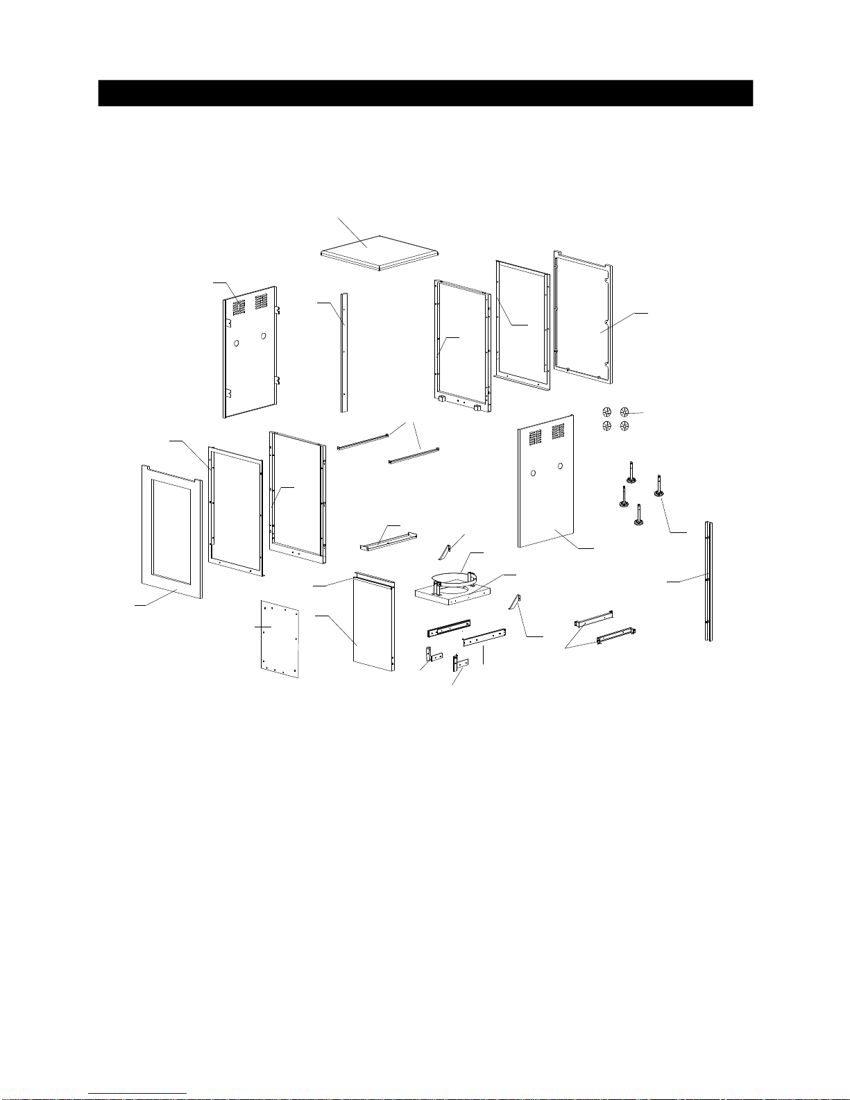
UsetheHardwareand Part Diagramstoensureall
itemsareincludedand freeofdamage.
Donotassembleoroperatethegrill ifitappears
damaged.If therearedamaged ormissingparts
whenyou unpack theshipping boxoryou have
questions during the assemblyprocess,callthe:
•
•

4
HardwarePack PartsList forModelCGI08ALP
*TwoBatteries/AA includedintheHardwarePack.
PART# PARTDESCRIPTION QTYPURPOSEOFPART
P06024006A HardwarePack 1 Foruseinassembly(Grilland Range)
S112G04061 PhillipsHeadScrew1/4"x3/8" 8 InstallCartFramestoLeft /RightBowlPanels
S162M04201 HexHead ScrewM4X20mm 2 SecureFaucetWasherand Faucet BrackettoFaucet
S233G04084 Wing Bolt1/4"x1/2" 1 SecuresGasTanktoTankHolder
P05515017L Wrench 1Adjustlevelon Island AssemblySet
Alreadypackedinthe FaucetAssemblyKitBox
AlreadyInstalledon TankHolder
Alreadypackedinthe Cooking ComponentsBox
PhillipsHeadScrew1/4"x3/8"
Qty.8
Part#S112G04061
Wing Bolt1/4"x1/2"
Qty.1
Part#S233G04084
Hardware alreadyinstalledon theTankHolder
Wrench
Qty.1
Part#P05515017L
Alreadypackedin theCooking ComponentsBox
•Alwayspurchasethe correctsizeand grade ofbattery mostsuitableforthe intended use.
•Replaceall batteriesofasetatthe sametime.
•Clean the battery contactsand alsothoseofthe devicepriortobattery installation.
•Ensurethe batteriesareinstalled correctlywithregardtopolarity(+and -).
•Removebatteriesfromequipmentwhichisnottobeused foran extended period oftime.
•Removeused batteriespromptly.
CORRECTBATTERYUSE

5
PartsDiagramforModelCGI08ALPGrill
82
14
13
21
22
1
2
3
5
6
7
10
8
9
16
17
23
27
28
29
34
35
37 44
31
24
19
18
15
12
25
45
4
11
32
33
42
36
43
26
30
74
39 40
38
5
41
41 46
47
48
49
50
51
52
53
54
55
56
57
60
59
57
61
62
58
71
72
73
75
76
77 78
67
68
70
20
64
65
66 63
69
79
77
78
81
80

6
PartsDiagramforModelCGI08ALPRange
1
3
4
24
5
6
7
25
8
9
10
14
13
12
15
16
17
18
19
20
21
23
28
29
31 32
34
26
35
37
38
39
40
41
56
45
46
47
48
22
54
60
57
59
61
58
55
42
2
11
30
43
50
57
53
49
62
27
63
51
52
36
64
65
30
31
67
66 66
67
68 69
44
13
70
71
72
73
33

7
PartsDiagramforModelCGI08ALPIsland
1
9
10 14
17
18
22
11
20 21
15
13
12
19
16
2
3
7
36
7
4
5
23
24
8

8
PartsList forModelCGI08ALPGrill
KEY DESCRIPTION PART# QTY
1LidAssembly P00147063A 1
2TemperatureGauge P00601071A 1
3LidHandle P00205086B 1
4Heat InsulatingSpacer P06801022A 2
5ProtectivePad P05518011I 2
6Cooking Rack/Secondary P01516004B 1
7Cooking Grid, 13" P01604013B 2
8Cooking Grid, 6.4" P01604031B 1
9Burner/Main P02008032A 3
10 InfraredBurnerAssembly P02005010A 1
11 Thermocouple P05305019A 1
12 SavorPlate®P01708033E 3
13 SavorPlate®Bracket, Front P033280504 3
14 SavorPlate®Bracket, Rear P033280514 3
15 BurnerBracket P02210034A 1
16 Back BurnerAssembly P02007068A 1
17 Back BurnerElectrode P02614025A 1
18 Back BurnerWindShield P06906046B 1
19 Back BurnerOrifice P06534005A 1
20 RefrigeratorBracket, Left P03329012D 1
21 Back BurnerThermocouple P05305022A 1
22 Back BurnerThermocoupleBracket P03328047C 1
23 BowlPanel, Front P0073878KA 1
24 BurnerHeat ShieldP06906045A 1
25 GreaseTrayHeat Shield P06904020C 1
26 GreaseTrayHeat Shield, Lower P06903050M 1
27 ElectricWireSet P02615121A 1
28 GasCollectorBoxwithElectrode P02609010B 3
29 GasValve/ManifoldAssembly Y0060571 1
30 GreaseDrainingPlate P06902006B 2
31 LightingStick P05507008A 1
32 BowlSupport Bracket, Left P01301006D 1
33 BowlSupport Bracket, Right P01302006D 1
34 ControlPanelExtension P02909768S 1
35 ControlPanelUpper P02915061S 1
36 ControlPanel P02915051S 1
37 ElectricIgnitor, 6-port P02502265C 1
38 ControlKnobSeat P03415014A 5
39 ControlKnob P03429065V 3
40 ControlKnobForBack Burner/InfraredBurner P03429075V 2
41 ControlKnobSpring P05504021A 5
42 NamePlate P00407010D 1
43 ElectricIgnitorProtector P05545002A 1
44 GreaseTray P02717454A 1
45 GreaseTrayHandle P00213012B 1
46 Cart Panel,Top P07805002A 1

9
PartsList forModelCGI08ALPGrill
KEY DESCRIPTION PART# QTY
47 Cart Panel,Front P07621009D 1
48 Cart FrameforFront Panel P03344010D 1
49 Cart Frame, Front P00907012C 1
50 Cart Panel,Rear/Left P07621010D 1
51 Cart Panel,Rear/Right P07621011D 1
52 Cart FrameforRearPanel P03344012D 1
53 Cart Frame, Rear P00907013C 1
54 Cart Panel,Right P07620003D 1
55 Cart Frame, Right P03305056D 1
56 BowlSupport Panel, A P03305057D 1
57 Cart Panel,Middle/Right P03305058D 2
58 RefrigeratorBracket, Right P03329013D 1
59 Slide Set P05516132C 1
60 BowlSupport Panel, B P03305059D 1
61 Drawer P01901011B 1
62 Handle/Drawer P00215033B 1
63 DoorforRefrigerator P04301040A 1
64 HoseHolder P05536001G 1
65 DoorBracket, Upper P03329014D 1
66 Refrigerator P05335020B 1
67 BowlPanel, Rear P0072588KA 1
68 BowlPanel, Left P0072083KA 1
69 DoorBracket, Lower P03329015D 1
70 BowlPanel, Right P0072184KA 1
71 ProtectiveCap P05535008I 1
72 LevelAdjuster P05322004A 4
73 Cart Frame, Left P01303017B 1
74 ThermocoupleBracket P03343008C 1
75 BowlWind Shield P00753019A 1
76 Back BurnerExtensionTube P03717050B 1
77 Cart BottomPanelBracket, LF/RR P03305060D 2
78 Cart BottomPanelBracket, RF/LR P03305061D 2
79 WireSet forRefrigerator P02615113A 1
80 ConnectionTube P03705088R 1
81 InfraredBurnerElectrode P02614052A 1
82 RegulatorWithHose P03637001A 1
Cover P07002064B 1
RotisserieAssembly Y0250122 1
HardwarePack P06024006A 1
Operator'sManual P80170008B 1

10
PartsList forModelCGI08ALPRange
KEY DESCRIPTION PART# QTY
1Lid P0014605AY 1
2ProtectivePad P05518011 I 2
3BowlPanel,Top P0073943DC 1
4BowlPanel,Left P0072075DC 1
5BowlPanel,Rear P0072575DC 1
6ControlPanel,Upper P02907971S 1
7ControlPanelBracket,Left P03328039C 1
8SideBurnerPotSupport P00815013D 1
9SideBurnerBody P01106044B 1
10 SideBurnerCap P02013058E 1
11 SideBurner P02004038B 1
12 FrameForGriddleBurnerA P0071340KA 1
13 GriddleBracket P03328041C 4
14 FrameForGriddleBurnerB P0071341KA 1
15 Griddle P05702020E 1
16 GrateHandles P05515014E 2
17 GreaseTube P02721042B 1
18 LightingTube P05507011A 1
19 Burner/Griddle P02008046B 1
20 SideBurnerElectrode P02607057A 1
21 GasCollectorBoxwithElectrode P02610026A 1
22 DoorBracket,Upper P03302036C 1
23 GasValve/ManifoldAssembly Y0060572 1
24 BowlPanel,Right P0072175DC 1
25 ControlPanelBracket,Right P03328040C 1
26 BowlSupportBracket,Right P01302006D 1
27 NamePlate P00407010D 1
28 ControlPanel P02913261A 1
29 ControlKnobSeat P03415014A 2
30 ControlKnobSpring P05504021A 2
31 ControlKnob P03429065V 2
32 ElectricIgnitor,2-Port P02502252C 1
33 DrainPipe P055120913 1
34 GreaseTray P02717465A 1
35 GreaseTrayHandle P00213011B 1
36 BowlSupportBracket,Left P01301006D 1
37 FaucetAssembly P05513006M 1
38 SinkFrame P07805003A 1
39 Sink P0071342BC 1
40 CartPanel,LeftRear P07702089G 1
41 CartPanel,RightRear P07702090G 1
42 CartFrameforRearPanel
P07702091B
1
43 CartFrame,Rear
P00907015C
1
44 DoorBracket,Bottom
P03302035C
1
45 CartFrame,Left
P03305056D
1
46 CartPanel,Left
P07702092G
1

11
PartsList forModelCGI08ALPRange
KEY DESCRIPTION PART# QTY
47 Handle/Door P00206005B 1
48 Door P04301041A 1
49 Cart Basket P05203008G 1
50 Cart BottomPanel P01001063D 1
51 DoorMagnet Bracket P03301051D 1
52 DoorMagnet P05523005M 2
53 BowlSupport Panel, B P03305059D 1
54 Slide Set P05516132C 1
55 Cart Frame, Right P01303017B 1
56 BowlSupport Panel, A P03305057D 1
57 Cart Panel,Middle/Right P03305058D 2
58 Drawer P01901010B 1
59 Cart Frame, Front P03344013D 1
60 Cart FrameforFront Panel P00907016C 1
61 Cart Panel,Front P07621012D 1
62 Level Adjuster P05322004A 4
63 ProtectiveCap P05535008I 1
64 Handle/Drawer P00204002B 1
65 CoverHook P05514133A 2
66 Cart BottomPanel Bracket, LF/RR P03305060D 2
67 Cart BottomPanel Bracket, RF/LR P03305061D 2
68 SinkBracket, Left P03303107D 1
69 SinkBracket, Right P03303108D 1
70 HoseHolder P05536001G 1
71 DrainAssembly P05512092A 1
72 Pipe Bracket P05512016G 1
73 ConnectionTube P03705088R 1
Cover P07002077B 1

12
PartsList forModelCGI08ALPIsland
KEY DESCRIPTION PART# QTY
1 TableTop P07805001A 1
2Panel, Front P07621006D 1
3FrameforPanelFront/Rear P03344009D 2
4Panel, Left P07605031H 1
5Panel, Right P07606032H 1
6Panel, Rear P07702088G 1
7Frame, Front/Rear P00907011C 2
8DecorationPanelA P03303049D 1
9Door P04301039A 1
10 Handle/Door P00216023B 1
11 Slide Set P05516132C 1
12 Slide Bracket B P03311014D 2
13 ProtectiveCap P05535008I 4
14 TankTray P04009030B 1
15 LevelAdjuster P05322004A 4
16 DoorBracket, Left P03302027C 1
17 DoorBracket, Right P03302028C 1
18 TankHolder P05358002Y 1
19 DoorTrimPanel P07510028A 1
20 LBracket, Left P03301049L 1
21 LBracket, Right P03301050L 1
22 DecorationPanelB P07621007D 1
23 UpperBracket forFront &RearPanels P03305054D 2
24 LowerBracket forFront &RearPanels P03305055D 1

13
Y0250122 RotisserieAssemblyPartsDiagram
Y0250122 RotisserieAssemblyPartsList
HardwareforRotisserie
Rot. Screw#10-24x3/4"
UNC
Qty.2
Part #S112G10121
Rot. Thumbscrew
1/4"x1/2"
Qty.3
Part #S196G04081
Rot.Washer
Qty.2
Part #S411G03081
Rot. Nut.#10-24
Qty.2
Part #S362G10121
KEY PART#
DESCRIPTION QTY
Rot.Bushing
Rot. Thumbscrew1/4"x1/2"
Rot.Collar
Rot. Spit
Rot. Holding Fork
Rot. MotorBracket
Rot.Motor/AC
Rot. Screw#10-24x3/4"UNC
Rot. Washer
Rot. Nut#10-24
1.
2.
3.
4.
5.
6.
7.
8.
9.
1
3
1
1
2
1
1
2
2
2
P05508092A
S196G04081
P05508168A
P05508175A
P05508023A
P05508174A
P07101042B
S112G10121
S411G03081
S362G10121
1.
2.
3.
4.
5.
6.
7.
8.
9.
10.
42
1
2
5
2
910
6
8
3
7

14
AssemblyInstructions
Install CartFrame (ForRangeModel)
PhillipsHeadScrew1/4"x3/8"
Qty.4
Part#S112G04061
Align the 4 holes intheCart Frameand theRange
Right(Front/Rear) Cart Legs.Insert the4Phillips
HeadScrews1/4"x3/8"and tightensecurely.
1
Install CartFrame (ForGrill Model)
Align the 4holes intheCart Frameand theGrill Left
Cart Legs(Front/Rear). Insert the4PhillipsHead
Screws1/4"x3/8"and tightensecurely.
2
AssembleIsland forGalley-StyleConfigration
Align the3individualmodules and slidetogetheras shownin
Option 1.
Besuretoattach theRegulatorwithHose installation from
Rangeand Island beforesecurelyplacing inposition.
(Please refertoStep4).
3-1
Note:
All measurementsareininches.
PhillipsHeadScrew1/4"x3/8"
Qty.4
Part#S112G04061
Tabletop surface 1
DO NOT lift Grill Island unitsfromthetabletop
surfaces whenmoving orassembling Island set.
CAUTION
! !
Option 1
Grill
Range Island
26.7"
34.3"
138.8"
1
1
1

15
AssemblyInstructions
Note:
All measurementsareininches.
SeparatetheIsland fromRangeand Grill modules.See Fig.1.
RemoveIsland Left, Rearand Decoration PanelsB.See Fig.2.
Door
Decoration PanelA
Fig.3 Fig.4
Range
Island
Grill
AssembleIsland forL-ShapeConfiguration
3-2
Use yourgrill atleast 3feetaway fromanywall
orsurface.
Donotobstructtheflowofairforcombustion
andventilation.
CAUTION
! !
RearPanel
Left Panel
Left Panel
Decoration PanelB
RearPanel
Fig.2
Option 2
Fig.1
Range
Grill
Island
Door
26.7"
56.5"
62.9"
26.7"
Reinstall Island Left Panel,RearPaneland Decoration PanelAas
shownin Fig.3.
Alignthe3individualmodules closelyas showninFigure4thenproceed
toStep4toattach theRegulatorwithHose.
Besuretoattach theRegulatorwithHose installation fromRange
and Island beforesecurelyplacing inposition.
(Please refertoStep4).

16
4Install RegulatorwithHose toHose Holder
(Thisassemblyprocess requires 2people)
Push backSleeve oftheSocket. See FigureA.InsertPlugthenreleaseSleeve.
See FigureB.Push Plug until sleevesnapsforwardlockingthePlug intothe
Socket. See FigureC.
CompleteinstallationofRegulatorwithHose forbothGrill and Range Plugs.
Open TankTrayDoor.(SeeFig.1)
ReplacetheDrawersand CloseTank Tray Door.
MoveIsland awayfromGrill and Rangeinordertogetaccess tooutside
oftheIsland sidepanels.
Pull thePlugsoutoftheGrill and Range.
Fig.1
RangePlug
Figure A
Figure B
Figure C
SLEEVE
SLEEVE
SOCKETPLUG
Option 1 Option 2
Grill Plug
Insert thePlugsoftheGrill and RangeintotheHoles oftheIsland.
R
Pushtenondown
ononesideand up
ontheothersideto
unlock
L
RemoveDrawersoftheGrill and Range.
SLEEVE
SOCKET
PLUG

17
Additional
Nut
Tanktray
Tank
Holder
5Install Gas TanktoTankTray
Open TankTrayDoor.
TurnyourLPGas Tank Valveclockwise totheclosedor
OFF positon.
UnscrewtheWing Boltfromrightbracketoftank holder.
PlaceLPGas tank intotank holderon theTank Tray.
Install thetank sotheTank Valvefaces therearright
cornerofcabinet.
Align anadditionalnutand screwtheWing Boltintoright
bracketoftank holdertosecurethegas tank.
Attach theRegulatorwithHose tothegas tank.
Close TankTrayDoor.
Keeptheventilation openingsoftheTank Traycabinet
free and clearofdebris.
CAUTION
! !
Tank Tray
Option 1 Option 2

18
Install FaucetAssembly(Thisassemblyprocess requires 2people)
TurntheFaucetclockwise and securelytightenit.(See Fig.2).
6
Fig.1
OpentheCart Door, removetheCart Baskettheninsert theFaucet.(See Fig.1).
Fig. 2
Underside
view
OutletforFaucet
and Sinkpiping
Sink
Frame
top
FaucetpipeInlet
Avoid breaking thecoppertube
fromthefaucet.
CAUTION:!
+ +
Faucetpipe
inlet
WaterPipe i.e.water
supplyhoseortubes
Pipe
tape
SinkFrame
top
Conneta5/8"watersupplyhose,pipeortube(notprovided)totheFaucetPipeInet.(See Fig.1)
CAUTION:Avoidbreaking the copperpipe byusing 2wrenches toconnectyourwatersupply
fitting tothe FaucetPipe Inlet. Use one wrench toholdthe Nuton the FaucetPipe Inletsteady.
Use asecond wrench toconnectyourwatersource.DO NOTover-tighten the connection or
twistthe Nuton the FaucetPipe Inletoryou maydamage the copperpipe.
5/8"
Feedtheloose end ofthepreassembleddrainpipethrough therearpanelsothesink drains
outsidethecabinet.
Feedyour5/8"watersupplyhose,pipeortubethrough therearpaneland connectitto
anappropriatewatersource.
ThisproductisprovidedwithaFaucetAssembly.
You canhavethefaucetplumbeddirectlytoyour
homes insidewatersupplyline(supplies not
included)soyouroutdoorsink canbeusedfor
washing food and dishes.However, ifyou electto
attach agardenhose toyourFaucetAssembly,be
awarethatinsomeU.S.States watersupplied
through agardenhose isregardedtobeunfitfor
humanconsumption.
CaliforniaProposition 65 Warning
!
Applypipetapeon theFaucetpipeinlet.

19
Install IgnitorBattery
UnscrewIgnitorCapfromRangeand Grill
ControlPanels.
PlacesuppliedAA batteryintotheIgnitor
Slotwithpositivepolefacing you.
Position theCapand Spring overtheAA
batteryand tightenontoControlPanel.
Install Cooking Components
PlacetheSavorPlates®above the
Burners.
PlacetheCooking Gridson theledge
abovetheSavorPlates®.
PlacetheSecondaryCooking Rack into
theholes on theupperleft and rightof
theBack Burnerframewiththebottom
resting intheslotson eithersideofthe
Grill Bowl.
SecondaryCooking Rack
SavorPlates®
10
Cooking Grids
7•
•
•
Using anadjustablewrench,loosenthe
InsideNutuntil theGas CollectorBoxcan
beturnedupward.
IfthegapbetweentheSparkElec-
trodeTipand Receiverismorethan
3/16"use long nose plierstogently
squeeze theGas CollectorBoxto
narrowgap.
ReturntheGas CollectorBoxtoits
originalposition,securetheInsideNut
and trytheElectrodeCheck again.Ifno
"clicking"sound isheard:
AA Batterymaybeinstalledback-
wards.
Electricwiresmay be loose.Remove
theAABatteryand inspecttheIgnitor
Junction Boxfound behind theControl
Paneland reconnectanyloose wires.
SideBurner ElectrodeCheck
-
Openrangelid.Removepacking mate-
rial(cardboardand styrofoam)from
burnerand potsupport.
Pushand turnsideburnerControlKnob
toHIGH/IGN.Look forsparkbetweentip
ofelectrodeand burner.
Ifyou don'tsee asparkfromsideburnerelec-
trode,adjustgapbetweenelectrodeand
burnersurfaceto3/16 in.
9
-
Besureall ControlKnobsaresetto
"OFF"and opentheGrill Lid.
Haveyourassistantstand behind tothe
rightofthegrill and look towardthefront
ofthegrill bowl. Never putyourface
insidetheGrill Head.
Press theIgnitorCap.You shouldhear
a"clicking"sound.Yourassistantshould
see abluesparkwithineach Gas
CollectorBox.Ifasparkispresentthe
ElectrodeTipsareproperlypositioned.
Ifno sparkisseen,theSparkGap
needstobeadjustedas follows:
Withtheassistance ofanother person,
perform thisElectrodeCheck before
proceeding
Thistestwillensurethatthe SparkElectrode Tips
areproperlypositionedsoyourgrilllightseasily
andproperly.
SparkElectrodeTip
SparkReceiver
SparkGap GasCollectorBox
8
8
Spring
IgnitorCap IgnitorSlot
AA Battery
AA Battery IgnitorSlot
Spring
IgnitorCap
Range ControlPanel
Grill ControlPanel

20
WARNING !
Failureto readandfollow theUseand Care
Instructionscouldresultinafireorexplosion
thatcouldcauseseriousbodilyinjury,deathor
propertydamage.
!
11 Install PotSupportand Griddle
PlaceSideBurnerCapon top ofsideburner.
Place PotSupportontop ofside burnerbody.
PlaceGriddleon top ofgriddleframewiththegrease
draininthefrontas shown.
PotSupport
Griddle
SideBurnerCap
FinalGrill AssemblyStep
Whenyou have finishedassembling your
grill besure thatall screwsare tightened
forsafeoperation ofyourgrill.
Wrench
Qty.1
Part#P05515017L
LevelAdjusterarelocated undersideoftheIslandAssemblyasshown.
OncetheIslandAssemblyisinitsfinallocation,reachunderneathandadjust
the 12pre-assembled LevelAdjustersif needed,usingthe wrenchprovided.
TurnAdjustersclockwisetoraisetheheightofthe Assemblyand
TurnAdjusterscounterclockwisetolowertheheight.
IMPORTANT:ForillustrationpurposetheIslandAssemblySetisshown
onatiltedangle. FORYOURSAFTEY DONOTTILT yourIslandAssembly
atanytime.
12 AdjustIsland AssemblySet(on unevensurfaces only)
UndersideviewofIsland AssemblySet
LevelAdjuster
Wrench
Table of contents
Other GrandCafe Grill manuals
Popular Grill manuals by other brands

Weber
Weber Genesis II E-335 Assembly guide

Tupperware
Tupperware MicroPro Series manual

Landmann
Landmann Vista Smoky Mountain 560200 Assembly and operating instructions

Coleman
Coleman RoadTrip 9945-700 Assembly and instruction manual

Bull
Bull OUTLAW 26038 Assembly & operating instructions

Princess
Princess Digital Grill Master Pro user manual

Lotus
Lotus CW-74G Installation and operating instructions

Roller Grill
Roller Grill Savoye Instructions for use and installation

Char-Broil
Char-Broil 463243812 Product guide

Kenmore
Kenmore PG-40406SOL-1 Use & care guide

Cuisinart
Cuisinart WM-SW2 INSTRUCTION AND RECIPE BOOKLET

Weber
Weber 71150 owner's guide