GrandCafe C3906ALP User manual

Ÿ
Ÿ
NOTETOASSEMBLER/INSTALLER:
Leavethismanualwiththeconsumer.
NOTETOCONSUMER:
Keepthismanualforfuturereference.
RECORDYOURSERIAL# __________________
(seesilverCSAlabelonmainbodyofgrill)
IMPORTANT:
Ÿ
Manual#P80170002A-Date:2006/02/28
Grill Information Center:
Callusfirst ifyou haveanyproblemwiththis
product.Wecan helpyouwithquestionsabout
assemblyandgrilloperationorifthereare
damaged ormissingpartswhen youunpack
thisunitfromtheshippingbox.Pleasecall
beforereturningtothestore.
1-800-761-5456
8am-4:30pmCST,Mondaythrough Friday
Liquid Propane Gas (LPG)
Grill
ModelC3906ALP
Failuretocomplywiththeseinstructionscould
resultinafireorexplosionthatcouldcause
seriousbodilyinjury,deathorpropertydamage.
Whetherthisgrill wasassembled byyouor
someoneelse,youmustreadthisentiremanual
beforeusing yourgrilltoensurethe grillis
properlyassembled,installedandmaintained.
Use yourgrill atleast3feetaway fromany
wall orsurface. Useyourgrill atleast 3feet
awayfromcombustibleobjectsthatcanmeltor
catchfire(suchasvinylorwood siding,fences
andoverhangs)orsourcesofignition including
pilot lightson waterheatersand liveelectrical
appliances.
THISGASAPPLIANCEISDESIGNEDFOR
OUTDOORUSEONLY.
Combustion byproductsproduced when using
thisproductcontainchemicalsknowntothe
Stateof Californiatocausecancer,birthde-
fects,orotherreproductiveharm.
Ÿ
Ÿ
Ÿ
Ÿ
Ÿ
WARNING
! !
OPERATOR'SMANUAL

Tableof Contents
PrimarySafetyWarnings...........................1-3
Pre-AssemblyInstructions..............................3
PartDiagramsandLists..........................4-8
AssemblyInstructions...............................9-11
Use&CareInstructions:
•GasSafetyand LeakTests...........12-14
•Lighting Instructions............................15-16
•Troubleshooting..........................................16
•Rotisserie Instruction...........................17-19
•Cleaning andMaintenance................20-21
•CookingGuide...................................A1-A5
•FrequentlyAsked Questions............A6-A7
WarrantyTerms...........................BackCover
DANGER
!!
1.
2
3.
4.
Ifyousmell gas:
Shutoff gas to theappliance.
Extinguishanyopenflame.
Openlid.
Ifodorcontinues, keepawayfrom
theappliance andimmediatelycall
your gas supplieroryour fire
department.
Donot storeoruse gasolineorother
flammable liquidsorvaporsinthe
vicinityof this oranyotherappli-
ances.
AnLPcylindernot connectedforuse
shall not bestoredinthevicinityof
this oranyotherappliance.
1.
2.
3.
WARNING
! !
Donot storespareLP cylinder
within10feet(3m)ofthisappliance.
Donot storeoruse gasolineor
otherflammable liquidsand
vaporswithin25 feet(8m)of this
appliance.
Whencookingwithoil/grease, do
not allowtheoil/grease to get
hotter350°F(177°C)
Donot leaveoil/grease unattended.
4.
1.
2.
WARNING
! !
WARNING
! !
•LPGgrillmodelsmustbeusedwithLiquid
PropaneGas and the regulatorassembly
supplied.NaturalGas modelsmustbe used
withNaturalGasonly.Anyattempttoconvert
thegrillfromonefueltypetoanotheris
hazardous andmustbeperformed bya
qualifiedgastechnicianonly,usingaNG
ConversionKitpurchasedfromGrand Hall.
Never use yourgas grill inagarage,porch,shed,
breezewayoranyotherenclosedarea.
Never obstructtheflow ofventilation airaround
yourgas grill housing.
Never disconnectthe gas regulatororanygas
fitting whileyourgrillislit.Alitgrillcanignite
leakinggas and causeafireorexplosionwhich
couldresultinproperty damage,personalinjury
ordeath.
Keepgas regulatorhose awayfromhotgrill
surfaces and dripping grease.Avoidunneces-
sarytwisting ofhose.Visuallyinspecthose
priortoeach use forcuts,cracks,excessive
wearorotherdamage.Ifthehose appears
damageddo notuse thegas grill.Call:
1-800-761-5456 foranauthorizedreplacement
hose.
•
•
•
•
TheGreaseDrainingTrayandGrease
Receptaclemustbevisuallyinspected
beforeeachgrilluse.Removeanygrease
andwashGreaseDrainingTrayand
GreaseReceptaclewithamildsoapand
warmwatersolution. Failuretocomply
withthese instructionscouldresultin
agrease fireorexplosionthatcould
cause seriousbodily injury,deathor
propertydamage.
WARNING
! !
2

Pre-AssemblyInstructionsForYourSafety
ToolsRequiredforAssembly include:
protectiveworkgloves
protectiveeyewear
Whileit ispossibleforone person tounpack thisgas
grill,obtainassistancefromanotherperson when
handling thelargepieces.
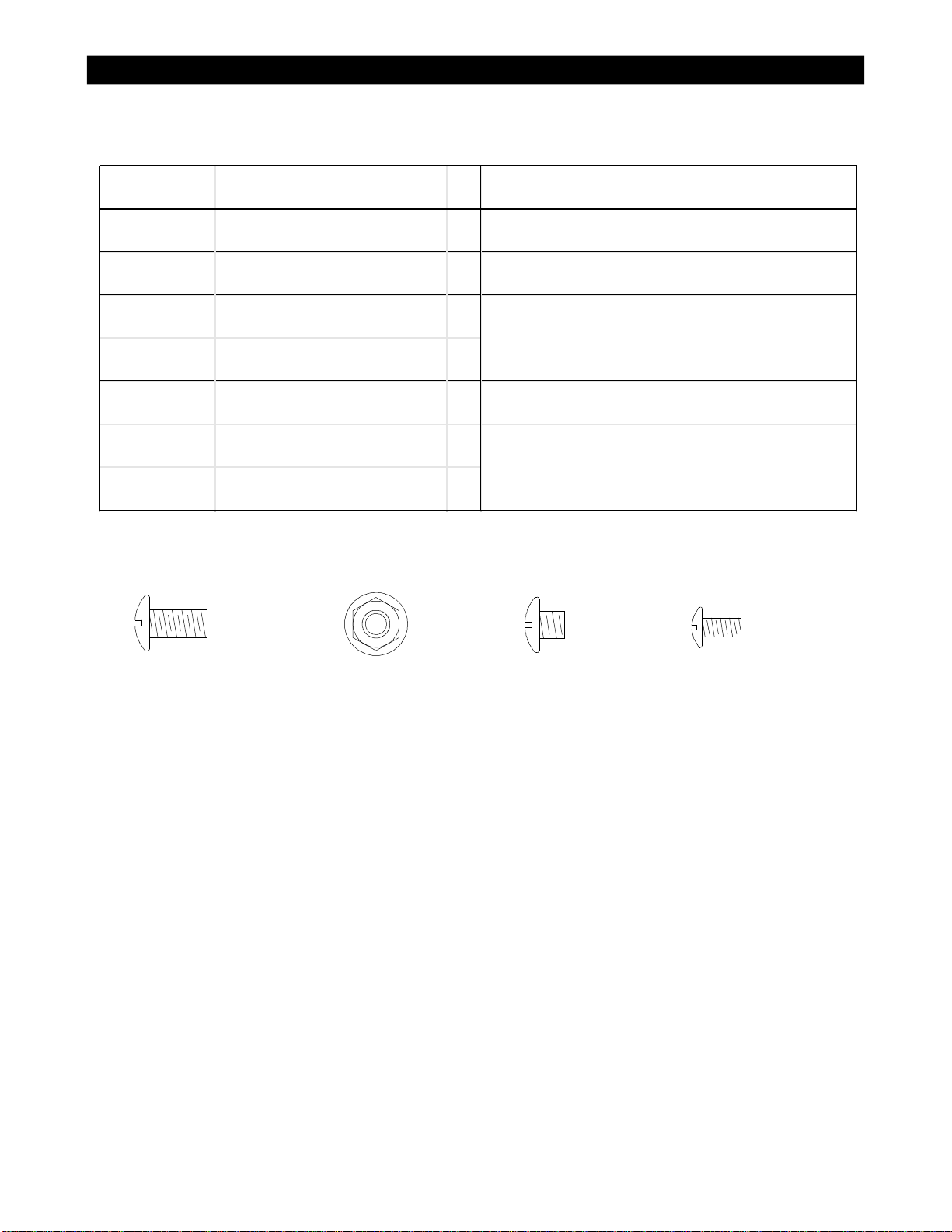
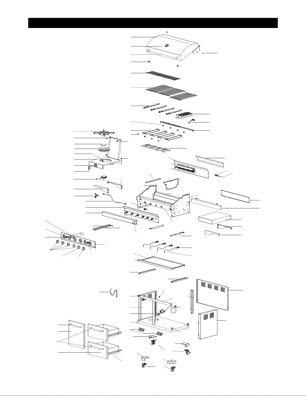
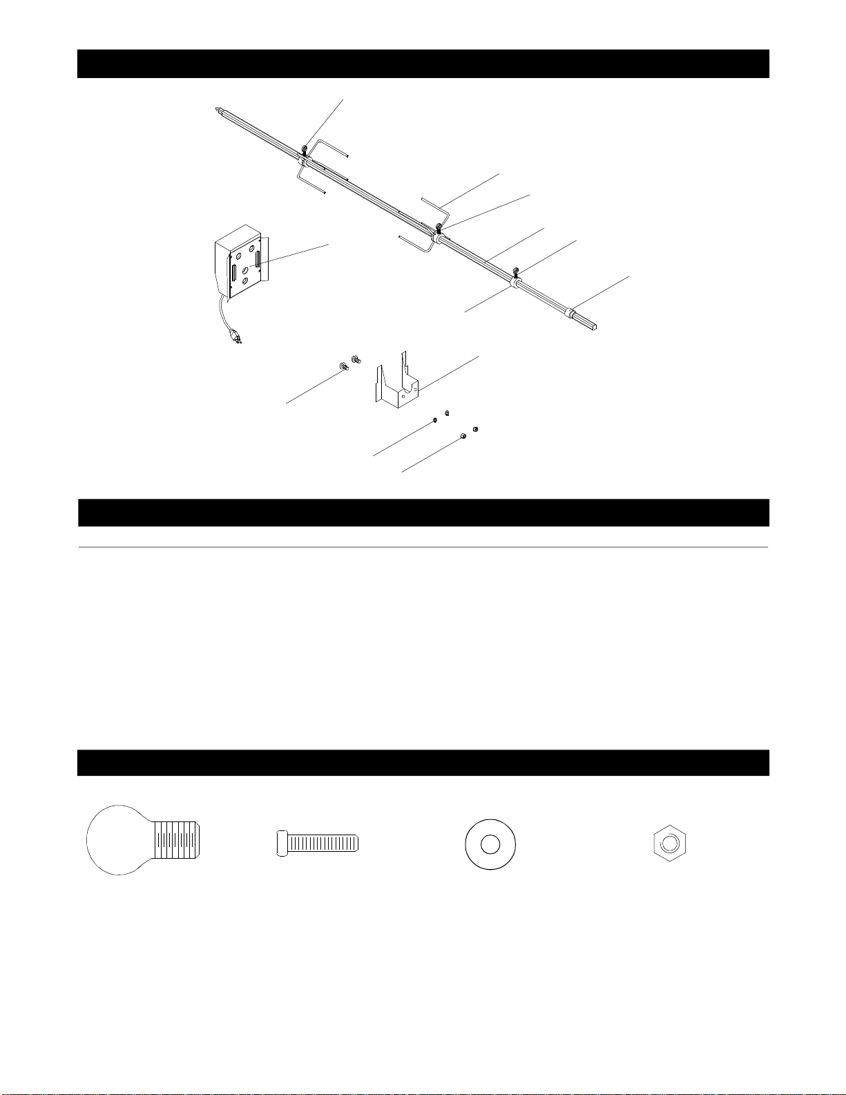
UsetheHardwareand Part Diagramstoensureall
itemsareincludedand freeofdamage.
Do notassembleoroperatethegrill ifitappears
damaged.If therearedamaged ormissingparts
whenyou unpack theshipping boxoryou have
questions during the assemblyprocess,callthe:
Toexpeditethe assemblyprocess follow these
general guidelines:
•
•
GrillInformationCenter 1-800-761-5456
8am-4:30pmCST,MondaythroughFriday
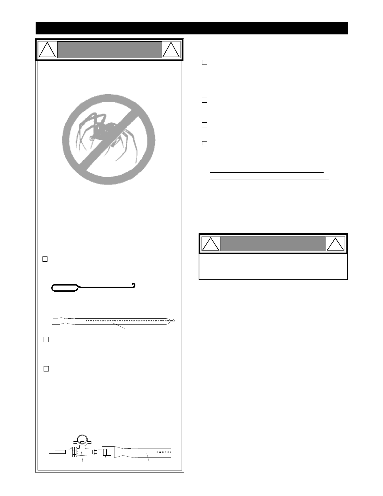
Spiders and small insectscanspinwebsand
nestinthegrill BurnerTubes during transitand
warehousing which canleadtoagas flow
obstruction resulting inafireinand around the
BurnerTubes.Thistypeof"FLASHBACK FIRE"
cancause seriousgrill damageand createan
unsafeoperating condition fortheuser.
Toreduce thechance ofFLASHBACK
FIREyou mustcleantheBurner Tubes
as followsbefore initialuse. Alsodo this
atleastonceamonthinsummerand fall or
wheneverspiders areactiveinyourarea,and if
yourgrill has notbeenusedforanextended
period oftime.
WARNING
! !
Failuretocomplywiththeseinstructionsmay
resultinahazardoussituationwhich,ifnot
avoided,mayresultininjury.
Forsafeoperation ensuretheGas ValveAssem-
blyOrificeisinsidetheBurnerTubebeforeusing
yourgrill.See figure.IftheOrificeisnotinside
theBurnerTube,lighting theBurnermaycause
explosion and/orfireresulting inseriousbodily
injuryand/orpropertydamage.
•
METHOD 1:Bend astiff wireorwirecoat
hangerintoasmall hook as shown and run
thehook through theBurnerTubeand inside
theBurnerseveraltimes toremovedebris.
METHOD 2:Use abottlebrushwithaflexible
handleand run thebrushthrough theBurner
Tubeand insidetheBurnerseveraltimes to
removeanydebris.
METHOD 3:Use anairhose toforceair
through each BurnerTube.Theforcedair
shouldpass debrisorobstructionsthrough
theBurnerand outthePorts.
TOCLEANBURNER TUBE,INSERTHOOK
HERE
BurnerTube
9
1.RemovethescrewsfromtherearofeachMain
BurnerusingaPhillipsHeadScrewdriver.
2.Carefullylift eachBurnerupandaway fromthe
GasValveOrifice.
3.Check andcleanBurner/VenturiTubesforinsects
andinsectnests.Acloggedtube can leadtoafire
beneaththegrill.
4.Refertothefigurebelow and performoneof
these 3cleaning methods:
Grill Installation Codes
Theinstallation mustconformwithlocalcodesor,inthe
absenceoflocalcodes,witheitherthe NationalFuel
Gas Code,ANSIZ223.1/NFPA54,NaturalGas and
Propane Installation Code,CSA B149.1, or Propane
Storage and Handling Code,B149.2.
Orifice BurnerTube
GasValveAssembly
CAUTION !
Whenusing electricalappliances,basic
safetyprecautionsshould always beused.
!
3
PhillipsHeadScrewdriver

HardwarePack PartsList forModelC3906ALP
*Two Batteries/AA includedintheHardwarePack.
PART#PARTDESCRIPTIONQTYPURPOSEOFPART
P06024002AHardwarePack1For useinassembly
S112G04081PhillipsHead Screw1/4"x1/2"8InstallSide ShelvestoLeft /Right Bowl Panels
S112G04061PhillipsHead Screw1/4"x3/8"3
S313G04081FlangeNut1/4"3
S112G03061PhillipsHead Screw3/16"x3/8"2SecureLeft/Right Side ShelvestoControlPanel
S112G04061PhillipsHead Screw1/4"x3/8"3
S313G04081FlangeNut1/4"3
SecureRightBowlPaneltoRightSide Shelf
SecureLeftBowlPaneland Side BurnerHoseBracketto
LeftSide BurnerShelf
PhillipsHeadScrew1/4"x1/2"
Qty.8
Part #S112G04081
FlangeNut1/4"
Qty.6
Part #S313G04081
PhillipsHeadScrew1/4"x3/8"
Qty.6
Part #S112G04061
PhillipsHeadScrew3/16"x3/8"
Qty.2
Part #S112G03061
4

PartsDiagramforModelC3906ALP
5
60
81
68
67
69b
69c
69a
39
69d
66
65
70
71
73
72 59
124a
42
27
18b
51
38b
64
32
4b
76
15
75 18a
17
21
26
8
28
29
24
78
53
36
80
25
43
46
48
50
45
49
54 47
31
30
37
46
35
33
79
52
56
6163
41
40
58
57
77
38a
51
22
55
23
16
20
19
52
62
1
3
6
4a
7
9
2
13
11
44 14
5
10
74
34a 34b

PartsList forModelC3906ALP
KEYDESCRIPTIONPART#QTY
1LidP00145036A1
2TemperatureGauge P00601071A 1
3LidHandleP00205068B1
4aProtectivePadP05518011 I4
4bProtectivePadP05518002I2
5LidHingeP05501020A2
6CookingRack/SecondaryP01517004B1
7
CookingGridP01604013B3
8
GreaseDraining Plate P06902006C2
9Burner/MainP02008024A4
10Infra-redBurner AssemblyP02005008A1
11Savor Plate®P01708033B4
12Savor Plate®Bracket,FrontP03328015A4
13Savor Plate®Bracket,RearP03328017A4
14BurnerBracketP02204104B1
15GreaseTrayHeatShieldP06904018C1
16BackBurnerWind ShieldP06906023C1
17BackBurnerFrameP06906022C1
18aBackBurnerAssemblyP02007053A1
18bBackBurnerElectrode AssemblyP02614025A1
19BackBurnerOrificeP06534005A1
20BackBurnerExtensionTubeP03717038B1
21BurnerHeat ShieldP06906039C1
22RearWind Shield,UpperP0075102BC1
23RearWind Shield,LowerP0075202BC1
24BowlPanel,FrontP0073862DC1
25BowlPanel,RearP0072562FC1
26BowlPanel,LeftP0072062EC1
27BowlPanel,RightP0072162EC1
28GasCollectorBoxwithElectrodeP02609007B4
29ElectricWireSetP02615087A1
30GasValve/ManifoldAssemblyY00603161
31ControlPanel,UpperP02910663A1
32ControlPanel,LowerP02910673A1
33ControlKnob for MainBurnerP03429012J4
34aControlKnob for Back Burner P03429022J1
34bControlKnob for Infra-red BurnerP03429122J1
35ElectricIgnitor,4-portP02502164C1
36ElectricIgnitor,2-portP02502172C1
37SmokerDrawerP06701017A1
38aGreaseTrayP02717173C1
38bGreaseTrayHandleP00213006B1
39Drawer Slide SetP01907006B4
40BowlSupportBracket,LeftP01301006B1
41BowlSupportBracket,RightP01302006B1
42Side Burner LidP0011540AA1
43Side Burner Cap P02013054B1
44Side Burner PotSupportP00814003A1
45ControlKnob ForSide BurnerP03429032J1
46ControlKnob SeatP03415014A7
47Side Burner Connection HoseP03705046J1
6

PartsList forModelC3906ALP
To obtainthecorrectreplacementparts foryourgas grill,please refertothepart numbers inthisparts
list. Thefollowing information isrequiredtoensureyou receivethecorrectparts:
1.Modeland SerialNumber(see CSA labelon grill)
2.Part Number
3.Part Description
4.Quantityofparts needed
Important: Use onlyfactoryauthorizedparts. Theuse ofanypart thatisnotfactoryauthorizedcanbe
dangerousand will alsovoidyourproductwarranty.KeepthisOperator'sManualforconvenientreferral
and forpart replacement.
Fortherepairorreplacementparts you need:
Call ourGrill Information Centerat 1-800-761-5456
KEYDESCRIPTIONPART#QTY
48Side Burner FrameP01106012B1
49Side Burner BodyP01106013B1
50Side BurnerP02004010A1
51Side ShelfBracket, LeftFront, RightRearP01211011A2
52Side ShelfBracket, Right Front, LeftRearP01213011A2
53QuickConnecterP03901027A1
54Side BunerGasValveAssemblyP03218030G1
55Side ShelfRightP01107039B1
56Regulator withhoseP03633003A1
57DoorHingeBracketP03314041C1
58CartSide Panel,LeftP07602019A1
59CartSide Panel,RightP07603019A1
60CartSupport, FrontP01907007B1
61CartSupport, RearP01907008B1
62CartRearPanelP07701056A1
63CartBracket,FrontP01316005B1
64ProtectiveCapP06801017G1
65CartReinforcingBracketP03328024C4
66 Caster2-1/2in. P05117008E2
67 Caster2-1/2in., withBrake P05117006E2
68CartBottomShelfP01010016C1
69aCasterSeat,LFP05327009Q1
69bCasterSeat,RFP05327011Q1
69cCasterSeat,LRP05327010Q1
69dCasterSeat,RRP05327012Q1
70DoorHandleP00205073B1
71Drawer HandleP00205080B2
72DoorP04302030A1
73DrawerP01901007B2
74Infra-redBurnerElectrode AssemblyY03200101
75 BowlWind Shield P0075301BC1
76 NamePlate P00407010D1
77Lighting StickP05507031E1
78Side Burner ElectrodeP02614027C1
79Smoker DrawerBracket,LeftP03328025A1
80Smoker DrawerBracket,RightP03328026A1
81WeightP05344002A2
CoverP07007033B1
RotisserieAssemblyY02501041
Operator ManualP80170002A1
HardwarePackP06024002A1
7

Y0250104 RotisserieAssemblyPartsDiagram
Y0250104 RotisserieAssemblyPartsList
HardwareforRotisserie
Rot. Screw#10-24x3/4"
UNC
Qty.2
Part #S112G10121
Rot. Thumbscrew
3/8"x1/2"
Qty.3
Part #S196G06081
Rot.Washer
Qty.2
Part #S411G03081
Rot. Nut.#10-24
Qty.2
Part #S362G10121
910
6
8
3
742
1
2
5
2
KEY PART#
DESCRIPTION QTY
Rot.Bushing
Rot. Thumbscrew3/8"x1/2"
Rot.Collar
Rot. Spit
Rot. Holding Fork
Rot. MotorBracket
Rot.Motor/AC
Rot. Screw#10-24x3/4"UNC
Rot. Washer
Rot. Nut#10-24
1.
2.
3.
4.
5.
6.
7.
8.
9.
1
3
1
1
2
1
1
2
2
2
P05508092A
S196G06081
P05508091A
P05508154A
P05508090A
P05508141A
P07101039B
S112G10121
S411G03081
S362G10121
1.
2.
3.
4.
5.
6.
7.
8.
9.
10.
8

AssemblyInstructions
PhillipsHeadScrew1/4"x1/2"
Qty.8
Part #S112G04081
1Install SideShelves toLeft and RightBowl
Panel
Insertthe2PhillipsHeadScrews1/4"x1/2"half-way
intoholes on upperrimRightBowlPanel.
Align theRightSideShelfkeyholes withthe2screws
(Fig.1)and tightenthe2screwssecurelyfromthe
undersideofSideShelf.
Insertthe2PhillipsHeadScrews1/4"x1/2"into
threadedholes on lowerrimRightBowlPanelfrom
theundersideofSideShelfand tightenthe2screws
securely.
RepeatforLeft SideBurnerFrame.(Fig.2).
2Secure RightBowl PaneltoRight
SideShelf
PhillipsHeadScrew1/4"x3/8"
Qty.3
Part #S112G04061
FlangeNut1/4"
Qty.3
Part.#S313G04081
Figure1
Figure2
Figure4
Figure3
PhillipsHeadScrew3/16"x3/8"
Qty.2
Part #S112G03061
Insertthe1PhillipsHeadScrew3/16"x3/8"into
threadedholes on Upperleft rimBowlPanelfrom
theundersideofSideShelfand tightensecurely
(Fig.3).
RepeatstepforLeft SideBurnerShelf.
SecureRightBowlPaneltoRightSideShelf using
3PhillipsHeadScrews1/4"x3/8"and 3Flangenuts
1/4"and tightensecurely.(Fig.4).
9

3Secure Left Bowl Paneland SideBurner
Hose BrackettoLeft SideBurner Shelf
middle
hole
Figure5
S
o
c
k
e
t
P
l
u
g
Figure A
Figure B
Figure C
SLEEVE
SOCKET
Sleeve
PLUG
Pushback SleeveoftheSocket. See FigureA.
InsertPlug thenreleaseSleeve.See FigureB.
PushPlug untilsleevesnapsforwardlocking the
Plug intotheSocket. See FigureC.
PushtheSideBurnerHoseintoSideBurnerHose
Bracket. (Fig.6).
Install SideBurner Connection Hose
4
PhillipsHeadScrew1/4"x3/8"
Qty.3
Part #S112G04061
FlangeNut1/4"
Qty.3
Part #S313G04081
Insert3PhillipsHeadScrews1/4"x3/8"and 3Flange
nuts1/4"toouterholes ofLeftBowlPaneland tighten
securely.(Fig.5).
SideBurner
Hose Bracket
SLEEVE
Figure6
10

Install IgnitorBattery
5UnscrewIgnitorCapfromControlPanel.
PlacesuppliedAA batteryintotheIgnitor
Slotwithpositivepolefacing you.
Position theCapand Spring overtheAA
batteryand tightenontoControlPanel.
Repeattoinstall theotherAA battery
intotheIgnitorSlot.
WARNING !
Failureto readandfollow theUseand Care
Instructionscouldresultinafireorexplosion
thatcouldcauseseriousbodilyinjury,deathor
propertydamage.
!
FinalGrill AssemblyStep
Whenyou have finishedassembling your
grill besure thatall screwsare tightened
forsafeoperation ofyourgrill.
Install Cooking Components
8PlacetheSavorPlates®ontheSavor
Plate®Rackandplace onthelower
ledge abovethe Burners.
PlacetheCooking Gridson theledge
abovetheSavorPlates®.
PlacetheSecondaryCooking Rack into
theholes on theupperleft and rightof
theBack Burnerframewiththebottom
resting intheslotson eithersideofthe
Grill Bowl.
+-
+-
AA Battery
AA Battery
IgnitorCap
IgnitorCap
Spring
IgnitorSlot
Spring
IgnitorSlot
Cooking Grids
SecondaryCooking Rack
SavorPlates®
11
Besureall ControlKnobsaresetto
"OFF"and opentheGrill Lid.
Haveyourassistantstand behind tothe
rightofthegrill and look towardthefront
ofthegrill bowl. Never putyourface
insidetheGrill Head.
Press theIgnitorCap.You shouldhear
a"clicking"sound.Yourassistantshould
see abluesparkwithineach Gas
CollectorBox.Ifasparkispresentthe
ElectrodeTipsareproperlypositioned.
Ifno sparkisseen,theSparkGap
needstobeadjustedas follows:
•
•
•
Using anadjustablewrench,loosenthe
InsideNutuntil theGas CollectorBoxcan
beturnedupward.
IfthegapbetweentheSparkElec-
trodeTipand Receiverismorethan
3/16"use long nose pliers togently
squeeze theGas CollectorBoxto
narrow gap.
ReturntheGas CollectorBoxtoits
originalposition,securetheInsideNut
and trytheElectrodeCheck again.Ifno
"clicking"sound isheard:
AA Batterymaybeinstalledback-
wards.
Electricwiresmay be loose.Remove
theAABatteryand inspecttheIgnitor
Junction Boxfound behind theControl
Paneland reconnectanyloose wires.
SideBurner ElectrodeCheck
7Opensideburnerlid.Removepacking
material(cardboardand styrofoam)from
burnerand potsupport.
Pushand turnsideburnerControlKnob
toHIGH.Look forsparkbetweentipof
electrodeand burner.
Ifyou don'tsee asparkfromsideburnerelec-
trode,adjustgapbetweenelectrodeand
burnersurfaceto3/16 in.
SparkElectrodeTip
SparkReceiver
-
-
Withtheassistance ofanother person,
perform thisElectrodeCheck before
proceeding.
6
Thistestwillensurethatthe SparkElectrode Tips
areproperlypositionedsoyourgrilllightseasily
andproperly.
SparkGap GasCollectorBox

USE AND CAREINSTRUCTIONS
CORRECTLPGASTANK USE
LPGasgrillmodelsaredesignedforusewitha
standard20lb.LiquidPropane Gas(LPGas)tank,
notincluded withgrill. Never connectyourgasgrillto
an LPGastankthatexceeds thiscapacity.Atankof
approximately12inchesindiameterby18-1/2inches
highisthe maximumsizeLPGastanktouse. You
mustusean "OPD"gastankwhichoffersalisted
Overfill PreventionDevice. Thissafetyfeature
preventstankfrombeingoverfilled whichcan cause
malfunctionofLPGastank,regulatorand/orgrill.
Never connectan unregulated LPgastanktoyour
gasgrill. Thegasregulatorassemblysuppliedwith
yourgasgrillisadjusted tohavean outletpressure
of11"watercolumn(W.C.)forconnectiontoanLP
gastank.Onlyusetheregulatorandhoseassembly
supplied withyourgasgrill. Replacementregulators
andhoseassembliesmustbethosespecifiedby
theManufacturer.
Have yourLPGasdealercheckthereleasevalve
afterevery fillingtoensureitremains freeofdefects.
Always keepLPGastankinuprightposition.
DonotsubjecttheLPGastanktoexcessive heat.
Neverstorean LPGastankindoors.If youstore
yourgasgrillinthe garage always disconnectthe
LPGastankfirstandstoreit safelyoutside.
LPGastanksmustbestored outdoorsinawell-
ventilated areaandoutofthe reachofchildren.
Disconnected LPGastanks mustnotbestoredina
building,garageoranyotherenclosed area.
The regulatorandhoseassemblycan be seen after
openingthe doors(ifapplicable)andmustbe
inspectedbeforeeachuseofthe grill. Ifthereis
excessiveabrasionorwearorif thehoseiscut,it
mustbe replaced priortousingthe grillagain.
Anyattempttoconvertthe grillfromonefueltype
toanotherisextremelyhazardous andmustbe
performedbyaqualifiedgas technicianonly,using
aNG Conversion KitpurchasedfromGrandHall.
Never lightyourgasgrillwiththelidclosedor
beforecheckingtoensurethe burnertubesarefully
seated overthe gasvalve orifices.
The LPGastankmustbe constructedandmarked
inaccordance withtheSpecifications forLP-Gas
CylindersoftheU.S.DepartmentofTransportation
(D.O.T.)orthe NationalStandardofCanada,CAN/
CSA-B339,Cylinders,SpheresandTubesfor
TransportationofDangerous Goods;andCommis-
sion,asapplicable.
The LPGastankmusthaveashutoffvalve,
terminatinginanLPGassupplytankvalve outlet,
thatiscompatiblewithaType1tankconnection
device.The LPGastankmustalso haveasafety
reliefdevice thathasadirectconnectionwiththe
vaporspace ofthetank.
The tanksupplysystemmustbe arranged forvapor
withdrawal.
The LPGastankusedmusthaveacollar
toprotectthetankvalve.
WARNING !!
DonotstoreaspareLP-Gastank underornear
thisappliance.
Neverfillthetankbeyond80percentfull; and
Ifthe information in"(a)"and"(b)"isnotfollowed
exactly,afirecausingdeathorseriousinjurymay
occur.
A.
B.
C.
•
•
•
WARNING
!!
Use yourgrill atleast3feetawayfromany
wall orsurface. Use yourgrill atleast 3feet
away fromcombustibleobjectsthatcanmelt
orcatch fire(such as vinylorwood siding,
fences and overhangs) orsources ofignition
including pilotlightson waterheaters and live
electricalappliances.
Never use yourgas grill inagarage,porch,shed,
breezewayoranyotherenclosedarea.
Never obstructtheflow ofventilation airaround
yourgas grill housing.
Never allowchildrentooperateyourgrill.Do
notallowchildren orpetstoplay nearyourgrill.
Use ofalcoholordrugsmayimpairtheabilityto
assembleand operatetheappliance.
Keepfireextinguisherreadilyaccessible.Inthe
eventofaoil/grease fire,do notattemptto
extinguishwithwater. Use typeBextinguisher
orsmotherwithdirt, sand orbaking soda.
Intheeventofrain,coverthegrill and turnoff
theburnerand gas supply.
Use yourgrill on alevel,stablesurfaceinan
area clearofcombustiblematerials.
Do notleavegrill unattendedwheninuse.
Do notmovetheappliancewheninuse.
Allow thegrill tocoolbeforemoving orstoring.
Do notuse yourgrill as aheater.
Thisgrill isnotintendedtobeinstalledin
oron recreationalvehicles and/orboats.
Thegrill isnotintendedforcommercialuse.
12

USE AND CAREINSTRUCTIONS
NOTEaboutLPGas TankExchangePrograms
Manyretailers thatsell grillsofferyou theoption of
replacing youremptyLP Gas tank through anex-
change service.Useonlythosereputableexchange
companiesthatinspect,precisionfill,testandcertify
theirtanks.Exchangeyourtank onlyforanOPD safety
feature-equippedtank as describedintheLP Gastank
sectionofthismanual.
Ÿ
How toLeak TestyourLPGas Tank
LPGasModelonly:
ConnectRegulatorwithHosetoyourLPGTank
Ifgrowingbubbles appeardo notuseormove
theLPGastank.ContactanLPGasSupplier
oryourfiredepartment!
WARNING
!!
Use acleanpaintbrushand a50/50 mildsoapand
watersolution.
BrushsoapysolutionontoLP Gastank inthe
areasindicatedbythearrows.Seediagram.
Ifgrowingbubbles appeardo notuseormovethe
LPGastank.Callan LPGasSupplieroryourFire
Department.
Allleaktestsmustberepeated each timeyourLP
Gastank isexchangedorrefilled.
Whencheckingforgas leaksdonotsmoke.
Donotusean openflametocheckforgas leaks.
Yourgrillmustbeleaktested outdoorsinawell-
ventilated area,awayfromignitionsources such as
gasfiredorelectricalappliances.Duringthe leak test,
keepyourgrillaway fromopenflamesorsparks.
Donotusehouseholdcleaningagents.Damage to
gas assemblycomponentscanresult.
Ÿ
Ÿ
Ÿ
Ÿ
Ÿ
Wing Bolt5/16"x4-1/2"
Qty.1
Ref. #S233G05461
Ÿ
Ÿ
Foryoursafety:
Leaktestnewand exchangedLP Gas tanksBEFORE
connecting onetoyourgrill.
Alwayskeepnewand exchangedLP Gas tanksinan
uprightpositionduringuse,transitorstorage.
Turnall BurnerValves totheOFFposition.
Inspectthevalveconnection port and regulator
assemblyfordamage ordebris.Remove any
debris.Neveruse damagedorpluggedequip-
ment.
Connecttheregulatorassemblytothetank valve
and HAND TIGHTEN nutclockwise toafull stop.
DONOT use awrench totightenbecause itcould
damagetheQuick Coupling Nutand resultina
hazardouscondition.
Openthetank valve1/4to1/2(counterclockwise)
and use asoapywatersolution tocheck all
connectionsforleaksbeforeattempting tolight
yourgrill.See "Checking forLP Gas Leaks".If
aleakisfound,turnthetank valveoff and do not
use yourgrill until theleakisrepaired.
Type1connectionper
ANSI Z21.58 -2005
Quick
Coupling Nut
CAUTION: Whentheapplianceisnotinuse thegas
mustbeturnedoff atthetank.
LPGas Modelonly:
Secure a20lb LPGas TanktoGas Grill
TurnyourLP Gas Tank Valveclockwise tothe
closedorOFF positon.
PlaceLP Gas tank intotank holeon bottomshelf
Install thetank sotheTank Valvefaces therear
rightcornerofcabinet.
ScrewtheWing Boltintosecurethegas tank.
13

USE AND CAREINSTRUCTIONS
Disconnecting ALiquid PropaneGas (LPG)
TankFromYourGrill
MakesuretheBurnerValves and LP Gas tank
valveareoff. (Turnclockwise toclose.)
Detach thehose and regulatorassemblyfrom
theLP Gas tank valvebyturning theQuick
Coupling Nutcounterclockwise.
WARNING !!
Ifyou haveagas leakthatcannotberepaired
bytightening,turnoffthe gas atthesource,
disconnectfuellinefromyourgrilland call
1-800-761-5456oryourgassupplierforrepair
assistance.
Checkall connectionsforLPGasLeaks
Never testforleakswithaflame.Priortofirstuse,
atthebeginningofeachseason,orevery time
yourLPGastankischanged,youmustcheckfor
gasleaks.Followthesethreesteps:
Makeasoapsolution bymixing onepart liquid
detergentand onepart water.
Turnthegrill ControlKnobstothefull OFF
position,thenturnthegas ON atsource.
Applythesoapsolution toall gas connections
indicatedbythearrows.Seediagram.If
bubbles appearinthesoapsolution the
connectionsarenotproperlysealed.Check
each fitting and tightenorrepairas necessary.
RegulatorwithHose(LPG)
LP GasTank
GasValve /Manifold Assembly
14

USE AND CAREINSTRUCTIONS
GrillLightingInstructions
Beforeeach use,check all hoses forcracks,nicks,cuts,
burnsorabrasions.Ifahose isdamagedinanyway,do
notuse yourgrill beforereplacing thehose withan
authorizedpart fromtheParts List. Alsomakesureall
gas supplyconnectionsaresecurelytightened.
Familiarize yourselfwiththesafetyand Use and Care
instructionsinthismanual.Do notsmokewhilelighting
grill orchecking gas supplyconnections.
BesuretheLP Gas tank isfilledortheNaturalGasLine
isattachedtothe gassource.
OpentheGrill Lid during lighting.
Check thattheend ofeach BurnerTubeisproperly
locatedovereach ValveOrifice.
5.
4.
3.
2.
1.
BackBurnerLightingInstructions
Follow steps1through 4ofthe GrillLighting
Instructions.
Then,pushand turntheBack BurnerControlKnob
toHIGH and press theelectricignitor3to4sec-
ondstolighttheBurner. Holdtheknob in10
secondsbeforereleasing.Ifignition does notoccur
follow step7beforeretrying.
1.
3.
2.
Afterthe Back Burnerislititwill reach cooking
temperaturequickly.Theorange/redglow will
evenoutwithinminutes.
IMPORTANT: Do notuse theBack Burnerand
MainBurners atthesametime.
BurnerControlKnobson ControlPanel
SetControlKnobstoOFF and opentheLP Gas
SLOWLY 1/4of aturn. ForNaturalGas
opentheShutOff Valveatsource.
Pushand turntheRIGHT MainBurnerControlKnob
toHIGH.AlwayslighttherightMainBurnerfirst.
Press theelectricignitor3to4secondstolightthe
burner.
Ifignition does notoccurin5seconds,turnthe
BurnerControl(s) off, wait5minutes,and repeatthe
lighting procedure.Ifignition still does notoccur,
turntheburnercontrol(s) and gas sourceOFF and
conductaleaktestofALL gas connectionsand gas
sources as explainedintheUse and Caresection
ofthismanual.Ifno leaksaredetected,wait5
minutes foranygas toclearand repeatthelighting
procedure.
AfteroneBurnerislit, turnthetank valveSLOWLY
onemore1/4ofaturnfor1/2ofonecompleteturn.
OnceoneMainBurnerislit, theadjacentBurnercan
belitbyturning itsControlKnob toHIGH.
6. tank valve
Open LP
gastank
9.
8.
7.
Pushand turn
Infra-redBurnerLighting Instructions
Follow steps1through 4oftheGrillLighting
Instructions.
Then,pushand turntheInfra-redBurnerControlKnob
toHIGH and press theelectricignitor3to4seconds
tolighttheburner.Holdtheknob in10 secondsbe-
forereleasing.Ifignition does notoccurfollow step7
beforeretrying.
AftertheInfra-redBurnerislititwill reach cooking
temperaturequickly.Theorange/redglow will even
outwithinminutes.
1.
3.
2.
HIGH
LOW
OFF
HIGH
OFF
HIGH
OFF
OFF
Failuretoreplaceafaultyhose,securegas supply
connectionsortoopentheLidbeforeproceeding
totheLighting Procedures couldresultinafire
orexplosion thatcouldcause seriousbodilyinjury,
death,orpropertydamage.
WARNING
! !
Follow steps1through 5oftheGrill Lighting
Instructions.
OpenSideBurnerLidduring lighting.
Pushand turntheControlKnob toHIGH.Thebuilt-in
sparkignitorwill lightthe burnerautomatically.
You mayhavetopushand turntheControlKnob up to
3to4times tolight.
Iftheburnerdoes notoccur,turntheBurnerControl
off, wait5minutes,and repeatthelighting procedure.
If ignition still does not occur,turntheburner control(s)
and gas sourceOFF and conductaleaktestofALL
gas connectionsand gas sources as explained in
theUse and Caresection ofthismanual.Ifno leaks
aredetected,wait5minutes foranygas toclearand
repeatthelightingprocedure.
1.
SideBurner Lighting Instructions
2.
3.
4.
5.
MainBurner Back
Burner Infra-red
Burner
15

USE AND CAREINSTRUCTIONS
Troubleshooting
Topurgeairfromyourgas lineand/orreset
theregulatorexcess gas flow device:
Ifthegrill failstolight:
ManuallyLighting YourGrill By Paper Match
To lightyourgas grill bymatch,insertamatch intothe
Lighting Stick and follow steps1through 6oftheGrill
Lighting Instructions.Then,lightthematch and place
Lighting Stick through theLighting Holeon theleft side
ofthegrill asshownbelow.TurnthenearestControl
Knob totheHIGH setting torelease gas.TheBurner
shouldlightimmediately.
Never leanoverthegrill cooking area while
lighting yourgas grill.Keepyourfaceand body
asafedistance(atleast18 inches)fromthe
Lighting HoleorBurners whenlighting yourgrill
bymatch.
WARNING
!!
Ifignition does notoccurin5seconds,turntheControl
Knob(s) and gas sourceOFF and conductaleaktest
as explainedintheUse and Caresection of thismanual.
Ifno leaksaredetected,wait5minutes foranygas
toclearand repeatthelighting procedure.
WARNING
!!
WARNING !!
ShouldaFLASHBACKfireoccurin oraround
theBurnerTubes,follow theinstructionsbelow.
Failuretocomplywiththeseinstructionscould
resultinafireorexplosionthatcouldcause
seriousbodilyinjury,death,orpropertydamage.
Shutoff gassupplytothe gasgrill.
Turnthe ControlKnobstoOFF position.
Open the Grill Lid.
PutoutanyflamewithaClass Bfire
extinguisher.
Oncethe grill hascooled down,clean
the BurnerTubesand Burnersaccording
tothe cleaning instructionsinthis
Operator's Manual.
Ÿ
Ÿ
Ÿ
Ÿ
Ÿ
TurnControlKnobstotheOFF position.
Turnoff thegas atthetank valve.
ForNaturalGas shutoff NG valve.
DisconnectregulatorfromLP Gas tank.
ForNaturalGas disconnectregulatorfrom12 ft.
NaturalGas Hose.
Letunitstand 5minutes toallow airtopurge.
ReconnectregulatortotheLP Gas tank.
ForNaturalGas reconnectregulatorto12 ft.
NaturalGas Hose.
Turntank valveon SLOWLY1/4ofaturn.
ForNaturalGas openShutOff valve.
OpentheGrill Lid.
PushandturntheRightMainBurnerControl
Knob to HIGH.
Press ElectricIgnitorfor3-4secondstolight
theburners.
WARNING
MisalignmentofBurnerTubesoverOrifices
Correction: RepositionBurnerTubesoverOrifices.
Obstruction ingas line
Correction: Removefuelline fromgrill. Donotsmoke!
Open gassupplyforone secondtoclearanyobstruction
fromfuelline.Closeoffgassupplyatsourceandrecon-
nectfuellinetogrill.
PluggedOrifice
Correction: RemoveBurners fromgrill byremoving the
screwfromtherearofeach Burnerusing long nose
pliers. Carefullylift each Burnerup and awayfromgas
valveOrifice.RemovetheOrificefromgas valveand
gentlyclearanyobstruction withafinewire.Then
reinstall all Orifices,Burners, screwsand cooking
components.
Ifanobstruction issuspectedinGas Valves orManifold,
call theGrill Information Center 1-800-761-5456 8amto
4:30pmCST,Mondaythrough Friday.
Obstruction inBurnerTubes
Correction: Follow theBurnerTubecleaning procedure
on page 21 ofthisOperator'sManual.
MisalignmentofIgnitoron Burner
Correction: Checkforproperposition oftheElectrode
Tipasshownin step 6page 11.Thegap betweenthe
SparkElectrode TipandSparkReceivershouldbe
approximately3/16".Adjustif necessary.Withthegas
supplyclosed,turnanyMainBurnerControlKnob to
IGNthenpush inandwatchforthepresenceofaspark
attheElectrode.
DisconnectedElectricWires
Correction: InspecttheIgnitorJunctionBoxfoundbehind
the ControlPanel. ConnectlooseElectricwiresto
JunctionBoxandtrytolightthe grill.
WeakAAbattery
Correction: UnscrewtheIgnitorCapand replacethe
battery.
Ifthegrill still does notlightyou mayneedtopurge
airfromthegas lineorresettheregulatorexcess
gas flow device. Note: Thisprocedureshouldbe
doneeverytimeanewLP Gas tank isconnectedto
yourgrill.
Turngas off atsourceand turnControlKnobstoOFF.
Waitatleast5minutesforgastoclear,thenretry.
Ifyourgrill still failstolight, check gas supplyand
connections.
Repeatlightingprocedure.Ifyourgrill still failsto
operate,turnthegas off atsource,turntheControl
KnobstoOFF,thencheck thefollowing:
1.
2.
3.
Match
LightingHole
Lighting
Stick
16

USE AND CAREINSTRUCTIONS
CORRECT ROTISSERIEUSE
Readall instructionsbeforeinitialuse.
IMPORTANT:Whenusing electricalappliances,basic
safetyprecautionsshouldalwaysbeused.
TheRotisserieMotorisset for120V,60HzAC current.
TheRotisserieisforoutdooruse only.
Do notletchildrenoperateorplaynearbyyourgrill or
Rotisserie.
ConnectingRotisserie
Alwaysattach theassembledRotisserietoyourgrill first
and thenplug theCordintoanoutlet.
Operating Rotisserie
Do notoperatetheRotisserieifthecordorplug be-
comes damaged,oriftheRotisseriemalfunctionsor
has beendamagedinanymanner.
Theuse ofaccessoryattachmentsisnotrecommeded
bythemanufacturerand maycause injuries.Do notuse
thisRotisserieotherthanintendeduse.
Do notimmerseElectricalCord,Plug orMotorinwater
orexpose torain,as thismayresultinanelectrical
shock.
DisconnectRotisserie
Carefulas all surfaces will behot, bothgrill and Rotis-
serieparts. Use protectivemittstohandletheRotis-
serie.
Unplug theRotisseriefromelectricaloutletwhennotin
use and beforecleaning.Allow tocoolbeforeadding or
removingparts.
WhenRoitsseriecooking placeaCooking Panunder
thefood tobecookedas thiswill capturethedrippings
and keepyourgrill cleanofexcess grease which could
cause afire.
CAUTION:Handlewithcarewhenmoving aCooking
Panwithhotoils
Shouldagrease fireoccur, turntheburners and gas off
and leavethegrill lidCloseduntil thefireisout.
Storethe Rotisserieindoors
WhenRotisserieisnotinuse,storeitindoors inadry
place.
5.
4.
3.
2.
1.
17

RotisserieInstructions
1. Removeallcomponentsfromthecarton.
Attachthe MotorBracketon the outside ofthe rightgrill bowlpanel.Align the twoholesofthe
Bracketwiththe holeson the grill bowl.Tighten securelyusing twoScrews#10-24x3/4"UNC,Plain
Washersand Nutsprovided.
2.
Slide aHolding Fork ontoeachend ofthe RotisserieSpit. Adjustspacing between Holding Forksto
accommodateyourfood,then tighten the Thumbscrewstokeep the Holding Forksinposition.Slide
the Collarand Bushing ontothe threaded end ofthe Spit. Do nottighten the CollarThumbscrewuntil
the Rotisserieisplaced intoyourgrill.
3.
Rot.Thumbscrew3/8"x1/2"x3
Holding Forks
Collar
Bushing
Thumbscrew
3/8"x1/2"
Spit
Thumbscrew
3/8"x1/2"
MotorBracket
OutsideofRight
Grill BowlPanel
Rot.Screw#10-24x3/4"
UNCwith
washersandnuts
Washer
#10-24 Nut.
Rot.Screw#10-24x3/4"UNCx2
Rot.Washerx2
Rot.Nut#10-24x2
18

Install the AC(alternating current)RotisserieMotorontothe MotorBracketasshownbelow.Besure
the Motorattachestothe Bracketwiththe electricalcorddown.Thisinstallation insuresthatonce
the Spitisinserted intothe Motoritwill alsorestsecurelyintothe slotofyourgrill bowl.
4.
Insertthe assembled Rotisserieintothe Motorasshownbelow.The Motorshouldbe on the right
side ofyourgrill and the Handleon the leftside.Placethe Bushing intothe slotopening on the
leftside ofyourgrill bowl,then tighten the CollarThumbscrewtothe rightofthe Bushing.The Collar
will stabilizethe Rotisserieduring the cooking process and the Bushing allowsthe RotisserieSpit
toturnsmoothly.Plug the Rotisserieintoan outletand turnon totest.
5.
BEFORErotisseriecooking you will need toremovethe Cooking Grid(s)and possiblythe SavorPlates®
fromyourgrill.When rotisseriecooking placeaCooking Pan underthe food tobe cooked.Thiswill
capturethe drippingsand keep yourgrill clean ofexcess greasewhichcouldcauseafire.Usecaution
when moving aCooking Pan containing hotoils.
The Bushing and Collar must alwaysbe used withthis Rotisserie.
Bushing
Collar
Thumbscrew
Spit
Holding Forks
Thumbscrew Motor
RotisserieMotor
MotorBracket
Rotisserie Spit mustrest
securelyinto theslot of
yourgrillbowl.
19

Propercareand maintenancewill keepyourgrill intop
operating condition and prolong itslife.Follow these
cleaning procedures on atimelybasisand yourgrill will
staycleanand operatewithminimumeffort.
CAUTION: Besureyourgrill isOFF and coolbeforecleaning.
CleaningTheCooking Grids
Beforeinitialuse,and periodically,washyour
Cooking Gridsinamildsoapand warmwater
solution.You canuse awashclothorvegetable
brushtocleanyourCooking Grids.
Cleaning TheSavorPlates®
Periodicallyyou shouldwashtheSavorPlates® ina
soapand warmwater solution. Use avegetablebrush
toremovestubbornburnt-on cooking residue.Drythe
SavorPlates® thoroughlybeforeyou reinstall theminto
thecooking bowl.
Cleaning TheGrease Tray and Receptacle
To reducethechanceoffire,theGrease Draining
Trayand Grease Receptacle(somemodels)
shouldbevisuallyinspectedbeforeeach grill use.
Removeanygrease and washGrease Trayand
Receptaclewithamildsoapand warmwater
solution.
Cleaning theInsideoftheGrill Lid
Grease canhaveatendencytobuildup on the
insideoftheGrill Lidand coulddripontodeck or
patiowhenthelidisopened.Visuallyinspectthe
insideoftheGrill Lidbeforeeach grill use.Remove
anygrease and washwithamildsoapand warm
watersolution.
AnnualCleaning ofTheGrill Interior
Burning-off excess food aftereverycookoutwill
keepitreadyforinstantuse.However,atleastevery
3monthsoras oftenas neededyou mustgivethe
entiregrill athorough cleaning tominimize yourrisk
ofgrease fireand keepthegrill intop shape.
Followthese steps:
Turnall BurnerValves tothefull OFF position.
TurntheLP gas tank valvetothefull OFF position.
ForNaturalGas shutoff valve.
Disconnecttheregulatorfromthegas tank.Inspect
thehose withregulatorassemblyforcracking,cuts
oranyotherdamage,and replaceas neccessary.
RefertotheParts ListinthisOperator'sManual.
Removeand cleantheSavorPlates®, Cooking
Grids,Cooking Rack and Grill Burners.
Covereach Gas ValveOrificewithaluminumfoil.
Brushtheinsideand bottomofthegrill withafiber
padornylon brushand washwithamildsoapand
warmwatersolution.Rinse thoroughlyand letdry.
Removealuminumfoil fromOrifices and check
each Orificeforobstruction.
Check each SparkElectrode,adjusting as needed.
ThespacebetweentheSparkElectrodeTipand
SparkReceivershouldbeapproximately3/16".
ReplacetheBurnersandadjusttheGas
CollectorBox.Theedgeofthecollectorboxshould
be overlapping theBurnerPort.
CLEANING AND MAINTENANCE
1.
2.
3.
4.
5.
6.
7.
8.
9.
10.
11.
Cleaning ExteriorStainless SteelSurfaces:
Weathering and extremeheatcancause exterior
stainless steelsurfaces toturntanincolor. Machine
oilsusedinthemanufacturing process ofstainless
steelcanalsocause thistanning color. Afterremov-
ing anyprotectivePVC filmfromtheGrill Lidand
ControlPaneluse aStainless SteelCleanertopolish
thestainless steelsurfaces ofyourgrill.Neveruse
abrasivecleaners orscrubbers because theywill
scratch and damageyourgrill.Follow these stepsfor
thebestresults.
1.TurntheLPGas tankvalve(clockwise)tothefull
OFFposition.Disconnecttheregulatorandhose
assemblyfromLPGastank.ForNaturalGas shut
off valveand disconnecttheNG regulatorand hose
fromvalve.Cover exposedgas fittingwith
aluminumfoil.
2.Removedirt orgrease using asoft clothand
polish stainlesssurfaces.Wipe withasoft cloth.
3.Removealuminumfoilfromexposedgasfitting
andallowgrilltoairdrybeforeattachingthe
regulatorandhose toyour LPGastank,or
attaching theregulatorand hosetoNaturalGas
valve.
ReplaceSavorPlates®andCooking Grids.
Reconnectthegas sourceand observethe
Burnerflameforcorrectoperation.
Keepgrill area clearand free fromcombustible
materials,gasolineand otherflammablevapors
andliquids.
Do notobstructtheflow ofairforcombustion
andventilation.
Keeptheventilation openingsofthetank enclosure
cabinetfree and clearofdebris.
Visuallycheck burnerflames occasionallyto
ensureproperflamepatternas shown below.
Failuretocomplywiththeseinstructionsmay
resultinahazardoussituationwhich,ifnot
avoided,mayresultininjury.
CAUTION
! !
MAGNIFIED VIEW
OF BURNER
FLAMETHROUGH
LIGHTING HOLE
20
Table of contents
Other GrandCafe Grill manuals
Popular Grill manuals by other brands

George Foreman
George Foreman GR10 instructions

Billabong
Billabong GBBPIC instruction manual

Star Manufacturing
Star Manufacturing STAR-MAX 8H-6015CBZ Installation and operating instructions

Pit Boss
Pit Boss PB1100PS1 Assembly and operation

Dacor
Dacor Epicure OB36 Planning guide

Kamino
Kamino BBQ 131971 User and assembly instructions