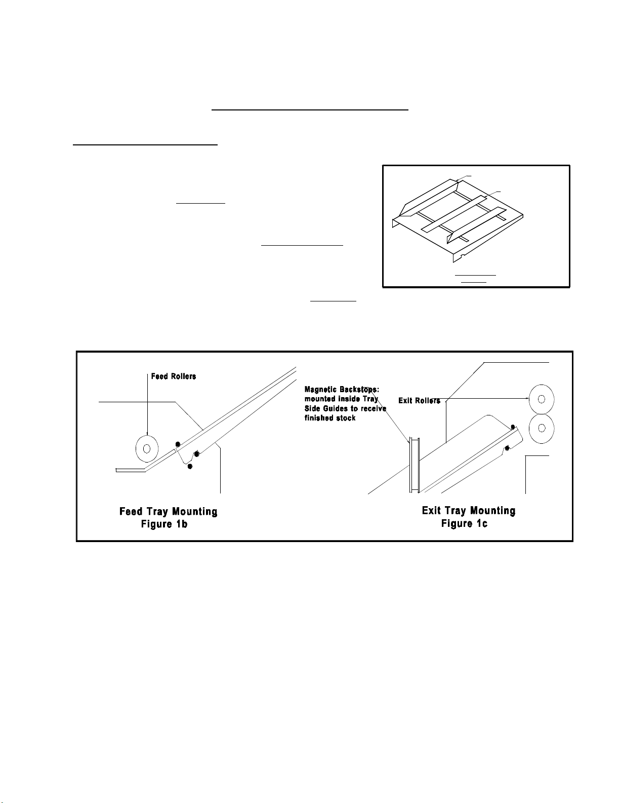
position of the magnets depends on the stock being processed, but the magnets should be set such that
the stock does not slide down the exit tray too far, possibly causing sheets to get in uncollated order.
2.2 Numbering Heads
The numbering heads are already secured
to the drive unit by two screws through
the numbering head mount block as
shown in Figure 2. The drive unit is then
mounted to the drive unit mount block
using the hand knob provided. While
installing the drive unit, make sure the
screw cap on the back of the drive unit
fits in the cavity on the drive unit mount
block so that the rubber plug provides
some pressure against the screw cap. You
may have to back out the left/right pitch
screw in order to do this. Plug in the cord
from the drive unitinto the appropriate
receptacle on the non-operator side cover
(closest head to the closest receptacle). If
your machine is equipped with more than
one head, by convention, the numbering
head and drive will refer to unit closest to
the operator control panel as head #1(H1)
and the other will be head #2 (H2).
The height of the numbering head has been factory set and it is critical to the proper performance
of the drive unit and numbering head. This distance is approximately 3" or the thickness of a numbering
wheel change stylus. However, the numbering head must be levelled to ensure that the numbering
wheels strikes the sheet square to provide a quality inked impression and a flat crash impression on
carbonless sets. This will be discussed later (Section 4.11).
The numbering heads can operate through 360Ε. This is done by loosening the numbering head
rotation screw (using the large hexdriver supplied) located on the front of the numbering head mount
block. Once the screw is loose, the head is free to rotate. Tighten the screw once the desired position is
achieved in order to prevent any movement during machine operation.
The standard numbering head is
3
/
16
" (4.5mm) Gothic style, reverse order, 6 digits with 2 drop wheels.
The numbering head employs a pre-inked pad, which can be purchased in red or black. These ink pads
will supply you with approximately 15,000 impressions. Uninked pads may be purchased if a different
colour is required (Note: any ink used must be a non-metal corrosive one, labelled numbering machine
ink).
The numbering head comes standard with six numbering wheels (a seventh numbering wheel is
optional), the last two of which are drop wheels (this will be discussed later). The first 5 digits may be
activated automatically. The 6th (or 7th) digit must be changed manually. Also available are letter
prefix wheels (A-J; K-R; S-Z) and a µprefix wheel. Modifications are possible with new numbering
head orders or by special order.
Change Stylus: Numbering
Head should be approx. 1/4"
from the platen, or the
thickness of a change stylus
Figure 2: Numbering Heads
Numbering Head
Mount Block
Numbering Head
Rotation Lock Screw
Numbering Head
Platen
Drive Unit
Drive Unit Mount Shaft
Anti-Pitch Block
Hand Knob
(Forward/Back Pitch)
Drive Unit Mount Block
Left/Right Pitch Screw
Forward/Back
Pitch Screw
Hand Knob
(Left/Right Pitch)
8