Graphic Whizard PT CR607 User manual

1
2020-10-20
Table of Contents
Introduction ..................................................................................................................................................2
Safety Precautions ........................................................................................................................................3
Specifications ................................................................................................................................................4
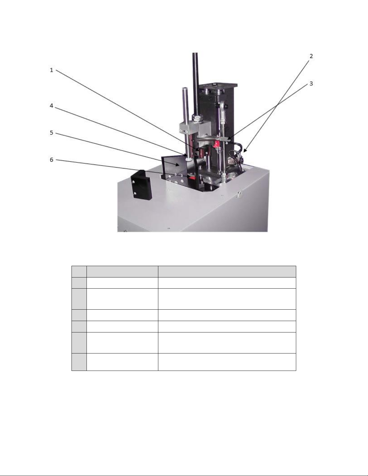
Overview.......................................................................................................................................................5
Operation......................................................................................................................................................7
Set-Up .......................................................................................................................................................7
Unpacking .................................................................................................................................................7
Initial Operation........................................................................................................................................8
Corner Rounding.......................................................................................................................................8
Selecting a Blade...................................................................................................................................8
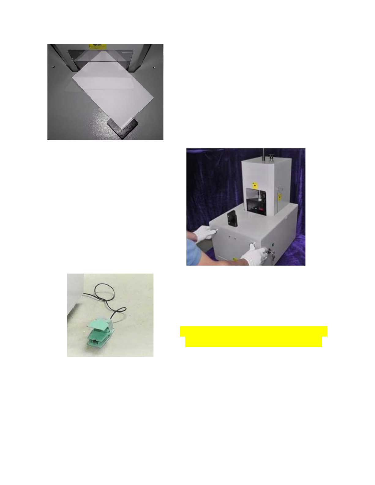
Loading Stock........................................................................................................................................9
Cutting Stock.........................................................................................................................................9
Foot Pedal .............................................................................................................................................9
Cut Stick ..............................................................................................................................................10
Installing Cutting Blades..............................................................................................................................11
Top Cover............................................................................................................................................11
Cutter Assembly..................................................................................................................................11
Removing Blades.................................................................................................................................12
Troubleshooting..........................................................................................................................................13
Red Light Indicator..................................................................................................................................13
Unable to Cut Through............................................................................................................................14
Round Corner Adjustment......................................................................................................................15
Maintenance...............................................................................................................................................18
Cleaning...................................................................................................................................................18
Lubrication ..............................................................................................................................................19
Wiring......................................................................................................................................................20

2
Introduction
The CR607 is equipped with an index turret multi-
tool cutting system which provides a series of
rounding radius from 2 to 10mm. The rounding
radius can be chosen by rotating to a different
cutting blade. It is used to round the corners of
paper material up to 2.36" thick like cards, copy
paper, etc. (DO NOT attempt to cut wood, plastic,
or metals).
The machine contains 7 turret mounted cutting
blades for rounding radius of 3mm, 4mm, 5mm,
6mm, 7mm, 8mm, and 9mm. It also contains one
empty carrier slot for optional rounding sizes
2mm or 10mm and a straight cut, either of which
can be installed as needed.
A crank mechanism is used to operate the
movement of corner rounding blades. During one
cycle, the rounding blades move downwards, cut,
and return to the original position.
An inter-lock system is installed to ensure the
safety of the operator. Three inter-lock switches
are placed in different areas and prevent the
machine from operating if problems occur.
To guarantee safety a minimum stack size of
1.75”x3.15” (45x80mm) is recommended. Any
smaller size may cause a personal safety hazard.
Use the foot pedal when working with a stack of
paper larger than 5.8”x8.25” (148x210mm). A
magnetic guide is provided to help align the stack
to ensure a uniform rounded edge.

3
Safety Precautions
DO NOT disassemble the machine with the power cord plugged in.
DO NOT operate with more than one operator.
Always exercise caution when performing maintenance.
DO NOT modify the machine.
DO NOT disassemble the machine when the power is on.
DO NOT operate the machine when the cover is open.
When using a foot pedal, keep hands away from the working area.
DO NOT operate with wet hands.
DO NOT touch any moving parts when in operation.
DO NOT use alcohol or organic solvents to clean the machines.
SWITCH OFF the machine and REMOVE THE POWER PLUG before cleaning.
Clean the machine periodically to maintain best performance.
Install and position the machine on a FLAT and STABLE surface.
Avoid positioning the machine in a humid or dusty environment.
Avoid direct sunshine.
Avoid nearby heat sources.
Avoid toxic and corrosive environments.
DO NOT touch wires, boards, etc. when power cord is plugged in.

4
Specifications
While every effort was made at time of publication to ensure accuracy, Graphic Whizard
Inc./Graphic Whizard USA Inc. will not be liable for omissions or errors. Specifications and
information are subject to change without notice. Actual results are dependent upon application.
Paper, print engine used, and environmental conditions will affect results.
Model Number
PT CR607
Power Supply
110-130V, 50/60Hz, 15A
Nominal Power
120W
Machine Dimensions
(WxLxH)
13.9”x 20.3”x 28.3”
35.4x 51.8x71.9 cm
Weight
47 kg / 103 lbs
Operating Temperature
10-35°C / 50-95°F
Operating Humidity
30-70%
Feeding Method
Manual
Input Paper Size
Min: 45mm-80mm / 1.76”-3.15”
Max: 148mm-210mm / 5.8”-8.25”
Thickness: 2.36"
Tabletop/Floor:
Tabletop *Optional stand available

5
Overview
No
Name
Description
No
Name
Description
1
Cutter Index
Rotate to change blades
8
Waste Tray
Collect paper waste
2
Lock Screw
Lock down cover
9
Error Indicator
Red light- safety switch disabled
3
Top Cover
For protection
10
Power Indicator
Green light- power on
4
Lever
Unlocks cutter turret
11
Left Start Button
Press both buttons together to
cycle the cutter once
5
Cut Stick Lock
Unlock cut stick tool
12
Right Start Button
6
Inching Button
Inching cutter up/down
13
Magnetic Side
Guide
Secures stack in place/safety
feature
7
Switch Key
Power on/off

6
No
Name
Description
1
Cutter Blade Turret
Rotating turret with 7 blades
2
Top Cover Safety Switch
For maintenance
3
Lever Switch
Press down to rotate blade turret
4
Card Press
Holds stack in place
5
Fixed Side Guides
Guides stack in place
6
Cut Stick
Consumable item that the cutting blade strikes
when completing a cycle

7
Operation
Set-Up
The following items listed below are included with the machine. If any one of them is missing,
please contact your dealer.
Name
Quantity
Allen Key (2.5mm)
1
Allen Key (4mm)
1
Extra Cut Sticks
5
Main Switch Key
2
Operation Manual
1
Magnetic Stopper
1
Power Cord
1
Foot Pedal
1
Blades (3mm, 4mm, 5mm, 6mm, 7mm, 8mm, and 9mm)
2 each -
14 total
Radius Guides
2
Unpacking
•Unscrew and remove wooden crate.
•At least two individuals capable of lifting 50 lbs each are required to lift the unit of the
pallet.
•Place he PT CR607 on a flat surface such as the optional stand or a table.
•Inspect the machine for the above listed parts and accessories.

8
Initial Operation
•The PT CR607 is shipped with the cutting tool in the down position to avoid possible
damage in transit.
•Attach power cord to socket at rear of the unit. Plug in to a receptacle (110v). There is
also a 3.15A fuse located in the socket.
•Insert the key and turn clockwise to power on.
•To operate the machine, the user must first return the cutting tool to its home position.
•Press the two-handed operation green Start buttons. The cutting tool will cycle to the
up/home position.
•Use caution. Do not place hands/fingers near cutting area as blades are sharp.
•The machine is now ready for use.
Corner Rounding
Selecting a Blade
With the power off press the lever down at the side of
the cover. Choose the radius by rotating the shaft at the
top of the machine. The radius size is indicated on the
shaft and will face the operator once locked in place.
When you hear a click
sound that means the
cutter is locked and ready
to cut.
The face of blade is also
marked with the radius
size for operator
convenience.
Cutter not
in place
Cutter in
place

9
Loading Stock
Insert a stack of cards in between the fixed side guides.
Place magnetic guide at the open end of stack for safety.
This will also keep stack tight to achieve straight cuts.
Cutting Stock
After loading stock press both green Start
buttons to activate the cutter. The machine will
cycle once.
Foot Pedal
Use the foot pedal to activate the cutter when
rounding larger stock that requires the operator to
hold onto the paper.
CAUTION: NEVER PLACE HANDS/FINGERS
NEAR BLADES WHEN IN OPERATION!!!

10
Cut Stick
The cut stick can be rotated or replaced when
needed. Pull back and hold the spring loaded
cut stick lock on the side of the machine.
Remove the cut stick to rotate or replace. Next replace
the cut stick by installing it on the holder.
Use the hole in the center of the stick to
thread the locking shaft. Release the cut stick
lock and the shaft to secure the cut stick back
into position.

11
Installing Cutting Blades
Top Cover
First, remove the top cover by
removing the securing knob from
the top of the cover.
Next, remove the turret handle
knob using a 2mm Allen key
(provided). This will expose the
turret assembly.
Finally, slide off the safety cover.
This will expose the blade turret
assembly.
Cutter Assembly
Loosen the two set screws to
remove the round black metal
waste deflector located inside the
base of the cutter turret. This will
provide access to the blade screws.

12
Removing Blades
Identify the blade that requires removal. The blades should
be labeled according to size (R3-R9). The blade is secured in
the turret with a set screw that is fed from the rear. Rotate
the turret to access the set screw once you know the location
of the blade.
Note: Two of the blades set screws are behind the screws that
secure the black collar. When replacing one of these blades,
you will have to remove the set screw for the waste deflector
before you can access the set screw that secures the blade.
Loosen the set screw behind the blade and
remove the blade using the provided 4mm T-
handle Allen tool. Insert the new blade by
feeding it from the top. Carefully pull down on
the blade to remove if it does not easily slide
out.
Note: You do not have to completely remove
the screw. Loosen it enough to remove the
blade.
Using the metal radius guide that came with the corner
rounder, adjust the blade depth by gently holding the
plate flat against the blades. This will ensure the new
blade is at the same height as the rest of the blades.
Once set, tighten the screw. Replace the metal collar.
Replace the cover. Test the new blade for cut accuracy.

13
Troubleshooting
Red Light Indicator
If the red light on the front of the PT CR607 is lit the machine will not run. The following steps are designed
to help correct the issue.
•Make sure the power cord is connected.
•Restart the machine by switching off/on the main switch. If problem still exists, go to next step.
•Make sure the tool-switch lever is in the proper position and the inter-lock switch located inside
is pressed by the lever.
•Make sure the waste tray is closed and the inter-lock switch located inside is pressed by the tray.

14
•Make sure the top cover is securely in place and the inter-lock switch inside is pressed by the
cover. Ensure the cover is sitting flush for the switch to be activated.
•Please contact your dealer if any problems still exist after attempting the previous steps.
WARNING
Inter-lock switches are designed and installed to guarantee the safety of the operator. The machine is
designed to not function with unsecured inter-lock switches.
Unable to Cut Through
•Decrease the thickness of the stack. The stack height may need to be smaller if the stock is
harder/thicker than average.
•Replace the cutting blade. The cutting blade is a consumable which means it may have a
significant decrease in performance due to normal operational wear. Replace when needed.
•Reposition the cutting blades. The cutting may be influenced by the starting position of the
cutting blades. The cutting performance may be less than perfect when the starting position is
close to the stock.
•Replace the cut stick. The cut stick is a consumable part which means after prolonged use it may
wear beyond desired usage.

15
Round Corner Adjustment
Overcut (Left) Proper Cut (Middle) Undercut (Right)
The finished products can be classified into three types: overcut products, undercut products and proper
products. Overcut and undercut are caused if the side guides are not aligned. They may need to be micro-
adjusted to obtain a desirable product.
To realign the side guides first switch off the power. Remove the main
switch key and unplug the power cord before removing the cover.
After removing cover bypass cover safety switch and turn the
power back and for adjustment purposes only.

16
Use the Inching button to bring the cutting blade
all the way down to the cut stick.
Loosen the two screws on the back of the guide (not
the front) using a 4mm Allen key.
Do not remove the screws or the guides from the
machine. This will allow the operator to shift the
guides into position.

17
Use the radius guide to align the side guides to
the proper blade radius. Each corner of the
radius guide is cut and labelled to match the
blades. This is a very delicate process and may
take time to accurately align the side guides.
After aligning the side guides tighten
the side guide screws. Next test the
cutting on card stock. When satisfied
with results return the inter-lock switch
back to original position. The PT CR607
will not work if this step is not
completed. Replace the cover when
complete.

18
Maintenance
Cleaning
Dust or paper clippings should be cleaned after each use. Use compressed air or a brush to clean
surfaces. Dump the waste tray into the trash. Make sure the tray is replaced in the proper
position to activate the inter-lock switch.

19
Lubrication
Regularly lubricate bearings and shafts with 3-in-1 Oil or motor grease. This will ensure smooth
operation of the PT CR607.
Table of contents
Other Graphic Whizard Industrial Equipment manuals
Popular Industrial Equipment manuals by other brands

Bühler technologies
Bühler technologies GAS 222.11 Brief instructions

THK
THK Ball Spline instruction manual

Mitek
Mitek RoofTracker II Service bulletin

GBC
GBC USP 13 Operator's manual

ABB
ABB 2 Series Operation and installation manual

Sedgwick
Sedgwick PT255 Additional Installation, Operation and Maintenance Instructions