6
43AA-S2 Ear Simulator Kit (with prepolarized microphone)
A test set-up with the 43AA-S2 can be similar to that described above and shown in Fig. 3,
except that a 12AL Power Module or 12AQ Power Module is used. Alternatively, the output from
the 43AC-S2 can be fed directly into a CCP input of the analyzer/computer.
1For example from 50 Hz to 10kHz
Test Procedure
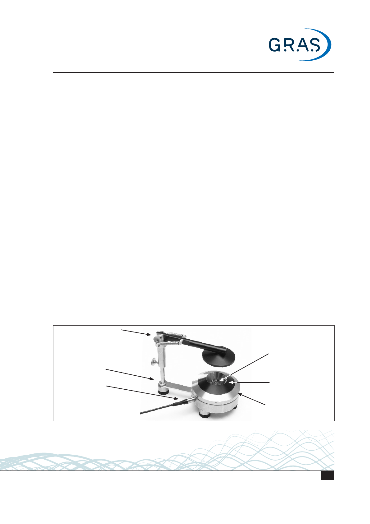
A possible test set-up for testing with 43AA is shown below. For testing with the prepolarized
43AA-S2 the power module can be replaced by a 12AL/12AQ Power Module. Alternatively, the
output can be fed directly to a CCP input of the analyzer.
Signal from generator to earphone
Computer with hardware and
software for simulating:
a signal generator capable
of generating logarithmically
swept tones and/or pink noise
an audio frequency analyser
capable of wide band and/or ⅓
octave band measurements
Output to analyzer
12AK Power Module
Input from
preamplifier
43AA with
earphone
Fig. 3. Block diagram of a complete set-up for making tests with the 43AA. With the 43AA-S2, the 12AL or 12AQ
Power module must be used, unless you connect directly to the CCP input of the computer/analyzer.
Overview: The 4 stages of the Test Procedure
The basic stages in the test procedure are:
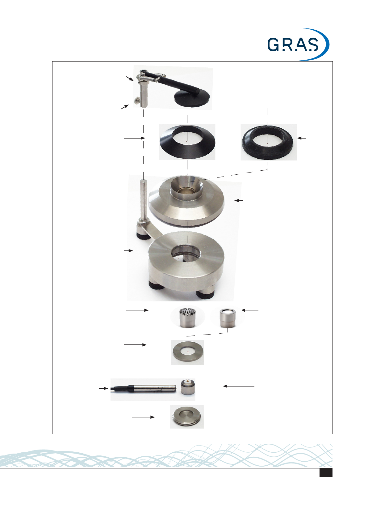
1) Setting up the test jig, e.g., as shown in Fig. 3.
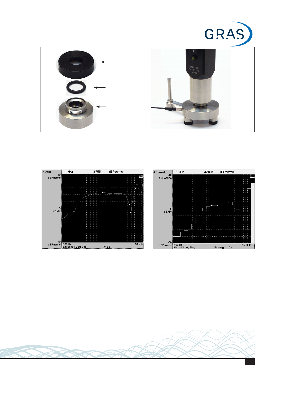
2) Calibration using the GRAS 42AA Pistonphone or GRAS 42AP Intelligent Pistonphone
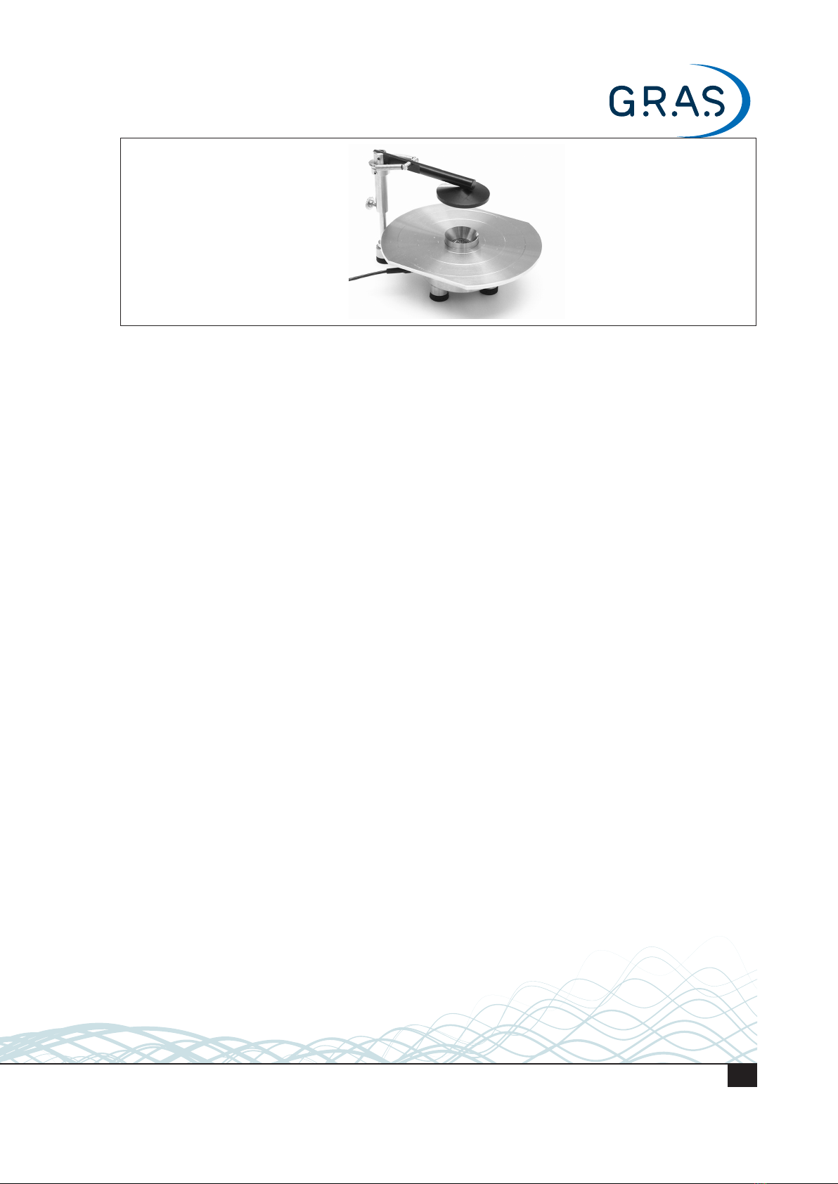
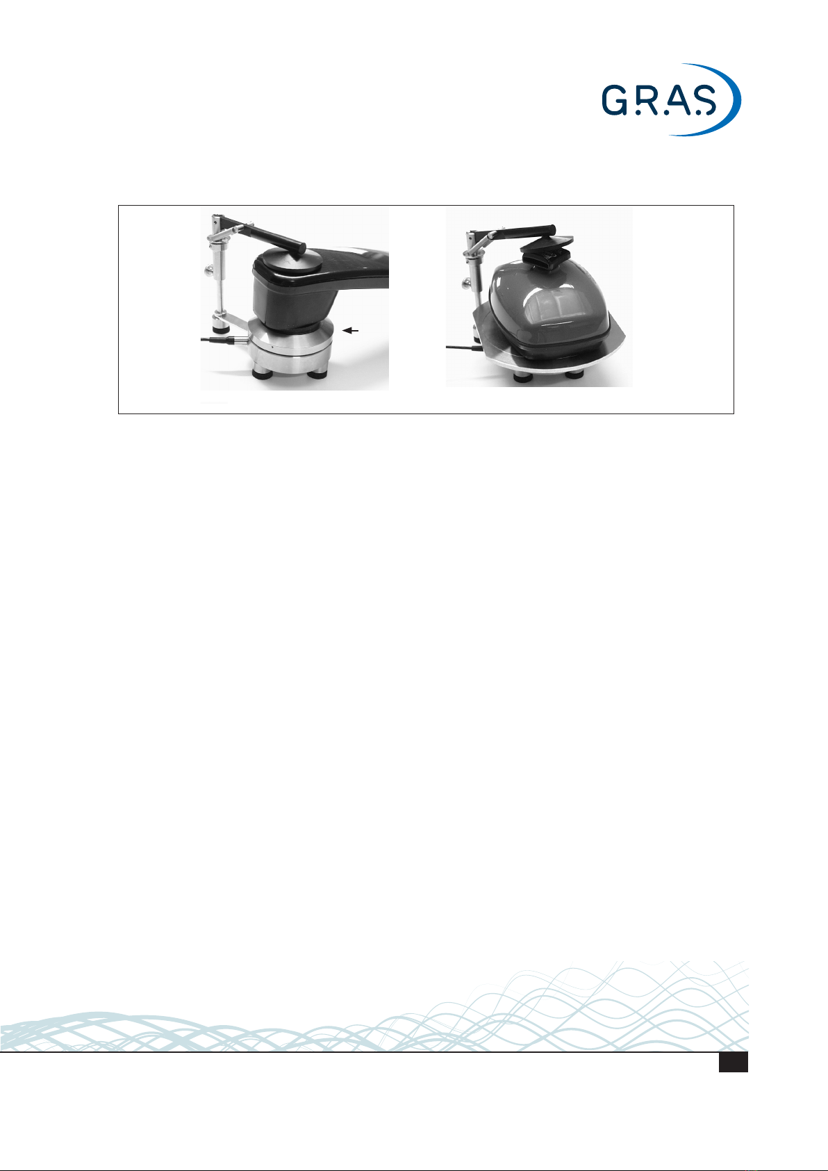
3) Mounting the earphone on the test jig (see examples shown in Fig. 4)
4) Applying a signal to the earphone and analyzing the output from the Ear Simulator.
Depending on requirements, the signal applied to the earphone could be:
a swept tone, e.g., under laboratory conditions
pink noise, e.g., during mass production of mobile telephones
Pink noise testing is usually quicker, and more economical, than using swept tones.
The following sections deal in more detail with each stage of the test procedure.
LI0066 – 1 June 2022