GRAS 43AD User manual

Instruction Manual
43AD Ear Simulator Kit According to ITU-T Rec. P57 Type 1
43AD-S1 Ear Simulator Kit According to ITU-T Rec. P57 Type 1,
prepolarized
www.gras.dk
LI0069 – 1 June 2022

Revision History
Revision Date Description
1 17 August 2017 Extracted from Earbook as separate document
2 1 June 2022 TEDS compatibility section added
Copyright Notice
© 2005–22 GRAS Sound & Vibration A/S
http://www.GRASacoustics.com
Any technical documentation that is made available by GRAS is the copyrighted work of GRAS
and is owned by GRAS.
The content in this document is subject to change without notice. GRAS Sound & Vibration A/S is
not liable or responsible for any errors or inaccuracies that may appear in this document.
Trademarks
Any other product names mentioned in this document may be trademarks or registered trade-
marks of their respective companies and are hereby acknowledged.
2
LI0069 – 1 June 2022

Contents
Introduction.................................................................................. 4
TEDS Compatibility .................................................................................... 4
Components.............................................................................................. 4
Additional Equipment ................................................................................. 6
Test Procedure .............................................................................. 7
The 4 stages of the Test Procedure .............................................................. 7
1: Setting up the Ear Simulator ................................................................... 7
3: Placing the Ear Simulator over the Earpiece/Earphone ................................ 8
4: Applying the Test Signal and Analysing the Output from the Microphone ...... 9
Warranty, Service and Repair......................................................... 11
Calibration............................................................................................... 11
Warranty................................................................................................. 11
Service and Repairs.................................................................................. 11
Appendix
The RA0039 Ear Simulator IEC 60318-1 ....................................... 12
Introduction ............................................................................................. 12
Components............................................................................................ 12
Characteristics ......................................................................................... 13
3
LI0069 – 1 June 2022

Introduction
The 43AD Ear Simulator Kit is a complete assembly for acoustically testing telephone handsets
and earphones and complies with the following international requirements:
IEC 60318 Electroacoustics – Simulators of human head and ear - Part 1: Ear simulator for
the calibration of supra-aural earphones.
ITU-T Recommendations P.57 Series P: Telephone transmission quality, Objective measur-
ing apparatus: Artificial ears.
The 43AD is acoustically similar to the 43AA. The main difference is that 43AD is quicker to use
when testing is part of the production process (e.g. mobile phones). It can also be calibrated rapidly.
43AD Ear Simulator Kit is also available in a prepolarized version, the 43AD-S1.
TEDS Compatibility
The prepolarized version, 43AA-1 is IEEE 1451.4 TEDS v. 1.0 compliant. If your measurement
platform supports Transducer Electronic Data Sheets (TEDS), you will be able to read and write
data like properties and calibration data.
Components
43AD Ear Simulator Kit According to ITU-T Rec. P57 Type 1, ext. polarized
The 43AD comprises the following main components:
RA0039 IEC 60318-1 Ear Simulator, see page 12
40AG ½” Pressure Microphone
26AK ½” Preamplifier
AA0008 3m Extension Cable
GR0332 Snap Coupling (female)
GR0336 Snap Coupling (male)
43AD-S1 Ear Simulator Kit According to ITU-T Rec. P57 Type 1, prepolarized
The 43AD-S1 comprises the following main components:
RA0039 IEC 60318-1 Ear Simulator, see page 12
40AO ½” Pressure Microphone, prepolariced
26CA ½” CCP Preamplifier
AA0034 2 m BNC Cable
GR0332 Snap Coupling (female)
GR0336 Snap Coupling (male)
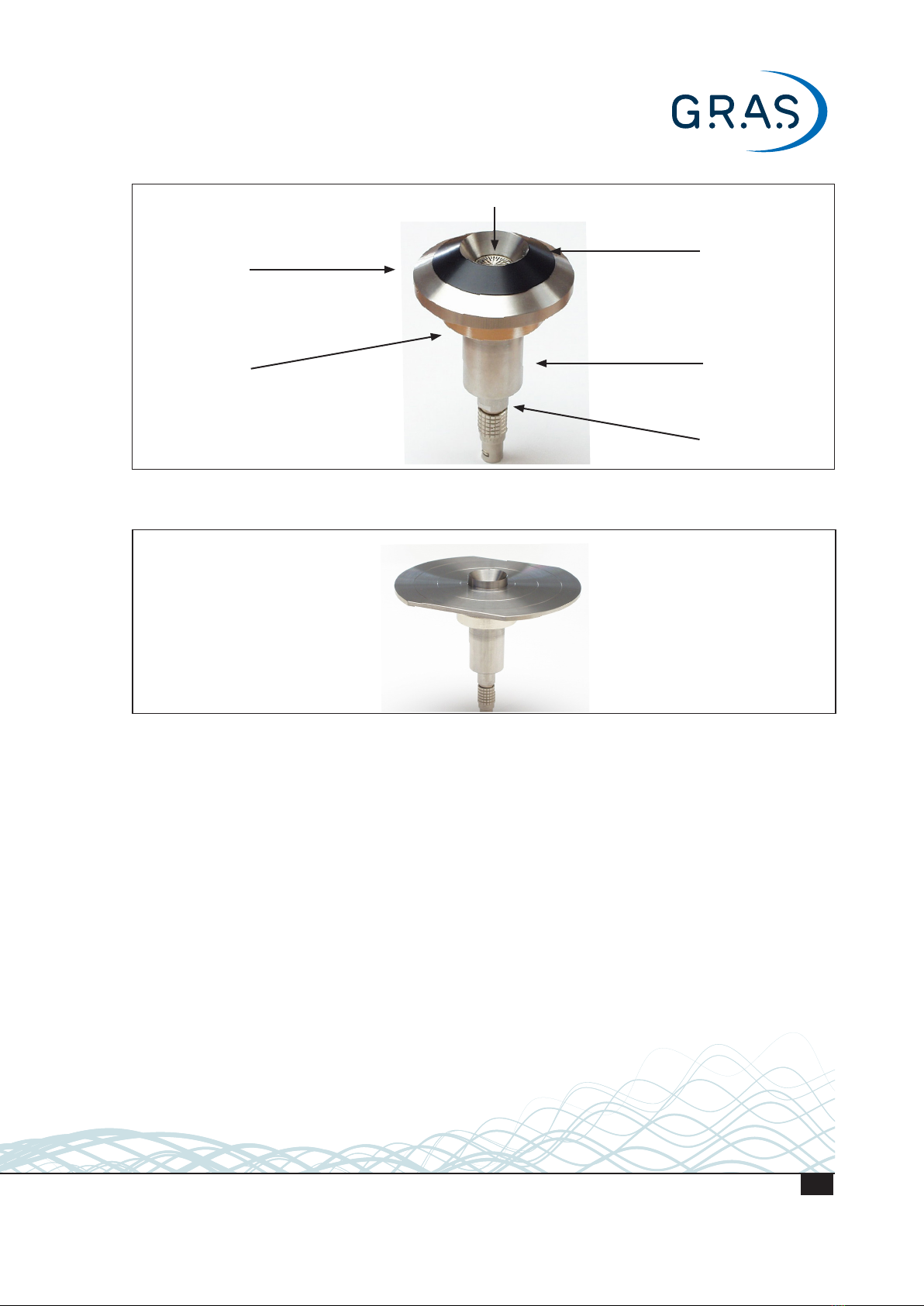
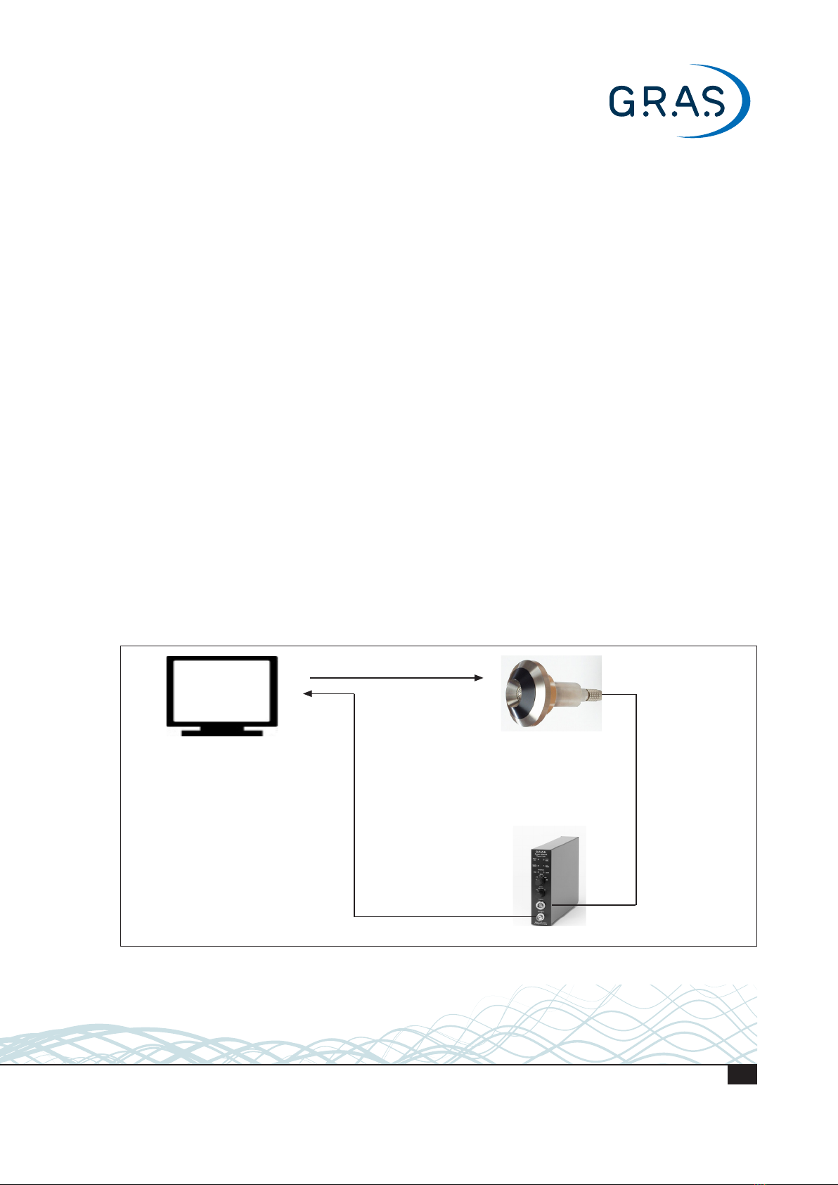
When assembled as shown in Fig. 1, it is ready for testing supra-aural 1 earphones such as telephone
handsets and headphones. Fig. 7 on page 10 shows an exploded view of its user-serviceable com-
ponents. The following mounting plate is also provided for testing circumaural2earphones:
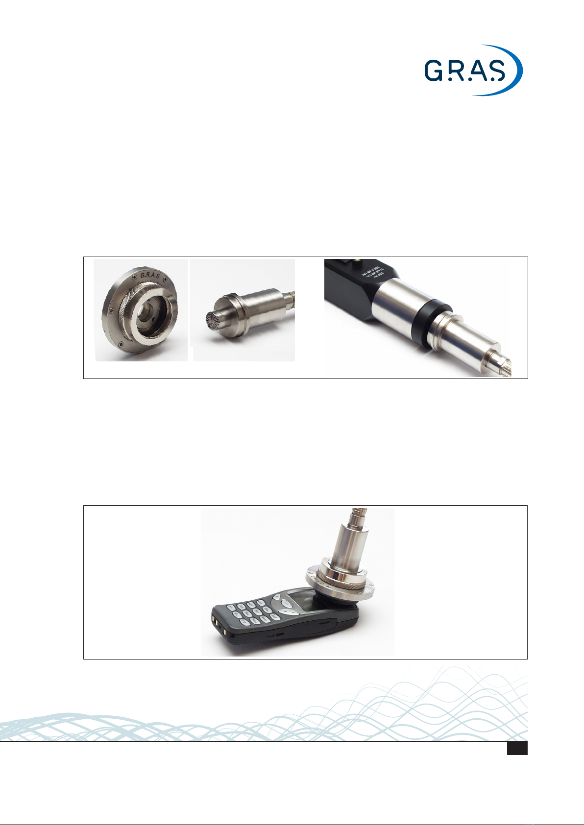
GR0339 for testing circumaural earphones
It has to be mounted accordingly in place of the removable ring (GR0338) surrounding the
entrance to the Ear Simulator, see Fig. 2.
1 An earphone applied externally to the ear
4
LI0069 – 1 June 2022

2An earphone with a cavity large enough to cover the region of the head which includes the ear. The concentric circles on the
GR0039 (Fig. 2) are provided to help place the earphone correctly in relation to the entrance to the Ear Simulator.
GR0332
Snap Coupling
(female)
½" preamplifier
GR0336
Snap Coupling
(male)
RA0039
Ear Simulator
½" microphone
GR0338
removable ring
Fig. 1. Assembled 43AD/43AD-S1 Ear Simulator Kit
Fig. 2. 43AD shown with mounting plate GR0339 for testing earphones fitted with fluid cushions (circum-aural)
Ground Loops
In certain test set-ups, particularly if they are automated, there can be a risk of ground loops
passing through the artificial ear and resulting in extraneous noise in the test results. If this is a
likely problem, please contact G.R.A.S. before ordering. The solution will be to use the prepolar-
ized version with protective grid and male snap coupling made of plastic.
5
LI0069 – 1 June 2022

Additional Equipment
43AD Ear Simulator Kit, externally polarized
The following additional equipment is required for making the necessary measurements:
1) Power supply for the 26AK ½” Preamplifier, e.g. the G.R.A.S. 12AK Power Module.
2) Calibration source for the microphone,
e.g. the G.R.A.S. 42AA or 42AP Pistonphone which produces 114 dB re. 20 μPa (10 Pa) at
250 Hz.
3) Audio signal generator capable of generating one or more of the following within the audio
frequency range3:
logarithmically swept tones
pink noise
This audio signal is fed (directly or indirectly) to the earphone.
4) Audio frequency analyzer capable of one or both of the following:
wide band measurement
⅓ octave-band measurement
The audio analyzer receives, via the 12AK (see Fig. 3), the signal picked up by the Ear Simulator,
and, depending on whether this is a swept tone or pink noise, will:
a) measure the response of the earphone to the swept tone
Or
b) measure the response of the earphone to the pink noise in terms of ⅓ octave bands
Items 3 and 4 could be combined in the same unit, e.g. a computer fitted with suitable hardware
and software for A/D and D/A conversions in order to simulate both a signal generator and an
analyzer. Fig. 3 shows a block diagram of a possible set-up for making tests.
Computer with hardware and
software for simulating:
a signal generator capable
of generating logarithmically
swept tones and/or pink noise
an audio frequency analyzer
capable of wide band and/or
⅓ octave band measurements
Signal from generator to earphone
Output to analyzer
12AK Power Module
Input from
preamplifier
43AD Ear
Simulator Kit
Fig. 3. Block diagram of a complete set-up for making tests with the externally polarized 43AD. With the 43AD-S1, the
12AL or 12AQ Power module can be used, or you can connect directly to a CCP input of the analyzer.
3 For example from 50 Hz to 10kHz
6
LI0069 – 1 June 2022

43AD-S1 Ear Simulator Kit, (with prepolarized microphone)
A test set-up with the 43AD-S1 can be similar to that described above and shown in Fig. 3,
except that a 12AL Power Module or 12AQ Power Module is used. Alternatively, the output from
the 43AC-S1 can be fed directly into a CCP input of the analyzer/computer.
Test Procedure
The 4 stages of the Test Procedure
Using the mobile phone as a typical example, the basic stages in the test procedure are:
1) Setting up the Ear Simulator, e.g. as shown in Fig. 3
2) Calibration using the G.R.A.S. 42AA or 42AP Pistonphone
3) Placing the Ear Simulator over the earpiece of the mobile phone (see example in Fig. 6)
4) Applying a signal to the mobile phone and analysing the output from the microphone.
Depending on requirements, the signal applied to the mobile phone could be:
a swept tone, e.g. under laboratory conditions
pink noise, e.g. during mass production of mobile telephones
The following sections deal in more detail with each stage of the test procedure.
1: Setting up the Ear Simulator
Note: the terms generator and analyzer refer to a set up which simultaneously sends the test
signal to the earphone and analyses the signal picked up by the Ear Simulator.
With the 43AD assembled and everything switched on, proceed as follows:
1) Power Module
Connect the free end of the preamplier cable to the Input socket.
Connect, via a suitable cable, the BNC Output to the input of the analyzer.
Select Lin.
Select a Gain that is within the input range of the analyzer.
2) Mobile phone
Connect the earphone of the mobile phone to the signal output of the generator.
3) Adjust the output level of the generator to lie within the normal working range of the earphone.
With the 43AD-S1, a 12AL Power Module or 12AQ Power Module can be used.
7
LI0069 – 1 June 2022

2: Calibration
For this, access to the microphone is necessary.
1) Twist open the two halves of the snap coupling as shown in Fig. 4.
2) Gently push the microphone into the Pistonphone’s coupler until it reaches the stop.
3) Switch the Pistonphone on.
4) Set the analyzer to either wide band or to the ⅓ octave band whose centre frequency is 250 Hz.
5) When conditions are stable, adjust the analyzer so that it correctly gauges the Pistonphone
signal (nominally 114 dB). See Pistonphone manual for making barometric corrections.
6) Switch the Pistonphone off and remove it from the microphone.
7) Re-assemble the Ear Simulator.
Fig. 4. Showing the two halves of the snap coupling to
give quick access to the microphone
Fig. 5. Gently push the microphone into the Piston-
phone’s coupler until it reaches the stop
3: Placing the Ear Simulator over the Earpiece/Earphone
In production testing, this is normally automated. The 43AD must be centrally placed over the
earpiece/earphone so that the sound is transmitted directly into the 43AD. See example in Fig. 6.
Note. For circumaural earphones, use the concentric circles on the mounting plate GR0339 for
guidance.
Fig. 6. Place the Ear Simulator centrally over the earpiece of the mobile phone
8
LI0069 – 1 June 2022

4: Applying the Test Signal and Analysing the Output from the Microphone
The following describes typical procedures for applying:
a) a swept signal
b) pink noise
In both cases, it is assumed that the generator and analyzer work to produce constant-confidence
results (i.e. maintaining a constant β Tproduct) in real time throughout the frequency range of
interest and make the measurement data available graphically and numerically.
Swept Signal
With everything set up as described above, proceed as follows:
a) set the generator to oscillator mode
b) set the analyzer to at response
c) initiate a constant-level logarithmic sweep4on the generator.
The analyzer will follow the response of the Ear Simulator to the earphone throughout the
sweep and record and display the results accordingly.
Pink noise
With everything set up as described above, proceed as follows:
a) set the generator to pink noise mode and start generating.
b) set the analyzer to ⅓ octave-band mode4and wait until conditions are stable.
c) start the analyzer.
The analyzer will record the response of the Ear Simulator to the earphone for each ⅓ octave
band and record and display the results accordingly.
In both cases, curves showing the upper and lower tolerance levels for the frequency range of
interest could be superimposed on the graphical displays.
4 For example from 50 Hz to 10kHz
9
LI0069 – 1 June 2022

GR0402
Removable
ring
GR0338
Removable
ring
GR0335
Body of
Ear Simulator
GR0332
Snap Coupling
(female)
GR0336
Snap Coupling
(male)
½" microphone
40AG or 40AO
½" preamplifier
26AK (shown) or 26CB
See “Ground
Loops” on page
5 concerning
risk of ground
loops
Fig. 7. Exploded view of all the user-serviceable components of the 43AD (mounting plates and extension cable omitted
for clarity)
10
LI0069 – 1 June 2022

Warranty, Service and Repair
Calibration
Before leaving the factory, all G.R.A.S. products are calibrated in a controlled laboratory environ-
ment using traceable calibration equipment.
We recommend a yearly recalibration at minimum, depending on the use, measurement environ-
ment, and internal quality control programs.
We recommend calibration prior to each use to ensure the accuracy of your measurements.
Warranty
Damaged diaphragms in microphones can be replaced. The microphone diaphragm, body, and
improved protection grid are made of high-grade stainless steel, which makes the microphone
resistant to physical damage, as well as corrosion caused by aggressive air or gasses. This,
combined with the reinforced gold-plated microphone terminal which guarantees a highly reli-
able connection,enables G.R.A.S. to offer 5 years warranty against defective materials and
workmanship.
The warranty does not cover products that are damaged due to negligent use, an incorrect power
supply, or an incorrect connection to the equipment.
Service and Repairs
All repairs are made at G.R.A.S. International Support Center located in Denmark. Our Support
Center is equipped with the newest test equipment and staffed with dedicated and highly skilled
engineers. Upon request, we make cost estimates based on fixed repair categories. If a product
covered by warranty is sent for service, it is repaired free of charge, unless the damage is the
result of negligent use or other violations of the warranty. All repairs are delivered with a service
report, as well as an updated calibration chart.
WEEE directive:
2002/96/EC
CE marking directive:
93/68/EEC
Manufactured to conform with:
RoHS directive:
2002/95/EC
G.R.A.S. Sound & Vibration continually strives to improve the quality of our products for our
customers; therefore, the specifications and accessories are subject to change.
11
LI0069 – 1 June 2022

Appendix
The RA0039 Ear Simulator IEC 60318-1
Introduction
The RA0039 IEC 318 Ear Simulator uses a ½” microphone, e.g. the externally polarized
G.R.A.S. 40AG or the prepolarized G.R.A.S 40AO. The artificial ear complies with the following
international requirements:
IEC 60318 Electroacoustics – Simulators of human head and ear - Part 1: Ear simulator for
the calibration of supra-aural earphones.
ITU-T Recommendations P.57 Series P: Telephone transmission quality, Objective measuring
apparatus: Artificial ears.
Components
The RA0039 comprises the following user-serviceable components:
GR0335 Body of Ear Simulator
GR0338 Removable Ring
GR0402 Removable Ring
GR0606 Guard Ring
GR0606 is a substitute for the normal protection grid of the 40AG Microphone if requirements
call for a LS2aP microphone. Note: this will leave the diaphragm of the microphone exposed!
The RA0039 is delivered as shown in Fig. 8. An exploded view of its user-serviceable compo-
nents is shown in Fig. 9.
It uses a ½” pressure microphone such as the G.R.A.S. 40AG with a 26AK ½” Preamplifier or ¼”
Preamplifier 26AC fitted with RA0001 Adapter. If ordered with a microphone, the RA0039 will
be calibrated with the specific microphone and delivered with the resulting calibration chart.
For a prepolarized setup, a 40AO microphone and a 26CB preamplifier are used.
Fig. 8. RA0039 Ear Simulator as delivered
GR0338
Removable
ring
GR0402
Removable
ring
GR0335
Body of
Ear Simulator
Fig. 9. Exploded view of all the user-serviceable components of the
RA0039
12
LI0069 – 1 June 2022

Characteristics
The acoustic input impedance of the RA0039 closely resembles that of the human ear and, as a
result, loads a sound source in very much the same way.
The RA0039 embodies a number of carefully designed volumes connected via well-defined and
precisely tuned capillary tubes. In an equivalent electrical circuit (see Fig. 10), capacitors would
represent the volumes, and inductance and resistance would represent respectively air mass
and air flow within the capillary tubes. The input impedance (see Fig. 11) is measured using a
special impedance probe as described in ITU-T Recommendations P.57 (08/96). This measures
the impedance of the RA0039 as seen from the Ear Reference Point (ERP). The impedance is
defined as the ratio of the sound pressure at the ERP to the corresponding particle velocity. The
sound pressure is measured with a probe microphone while a constant particle velocity is main-
tained via a high acoustic impedance sound source.
Fig. 10. RA0039 lumped parameter model
The sensitivity of the RA0039 at 1kHz is given both as the Open Ear Sensitivity and the Closed Ear
Sensitivity. The Open Ear Sensitivity is the ratio of the output signal from the preamplifier to the input
pressure signal at the ERP with open coupler. The Closed Ear Sensitivity is the ratio of the output
signal from the preamplifier to the input pressure signal at the ERP with closed coupler.
Fig. 11. RA0039 acoustic input impedance Fig. 12. RA0039 closed-coupler frequency response
13
LI0069 – 1 June 2022
Table of contents
Other GRAS Industrial Equipment manuals
Popular Industrial Equipment manuals by other brands

CKD
CKD HMF Series instruction manual

Erskine Attachments
Erskine Attachments 200001 Operator's manual

MKS
MKS Baratron 221B instruction manual

INTORQ
INTORQ 14.800 Series operating instructions

EDER Maschinenbau
EDER Maschinenbau ESG1 Operating instructions and spare parts list

Terex
Terex Genie Genie Lift Operator's manual