8
LI0084 – Revision 6 June 2014
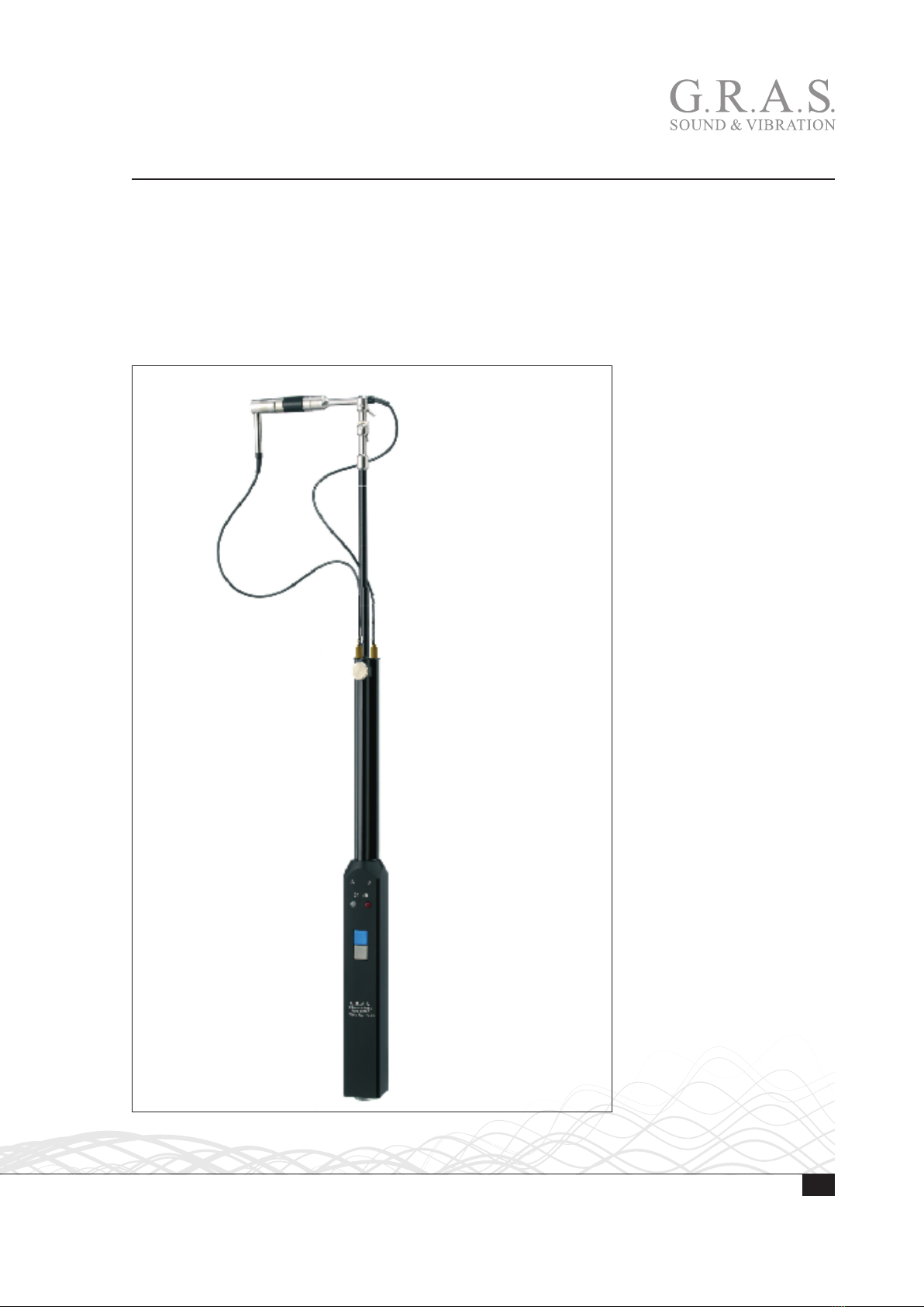
Handling and Assembling the Probe
The Microphones
The 40GK Microphones are a pair of special free-field microphones with extremely well-controlled
phase characteristics. They are delivered as a matched pair each with individual calibration data
as well as data on differences between their phase responses.
These microphones have a unique pressure equalisation system that ensures a well defined
lower-limiting frequency and an extremely low sensitivity to sound pressures at the pressure
equalisation channels. Therefore, they can be calibrated in single-port phase calibrators such as
the G.R.A.S. 51AB Intensity Calibrator.
Probe Design
The design of the Intensity Probe minimizes acoustic reflections and the influence of diffraction.
This has been achieved by removing any reflective components from the sound path at 0° inci-
dence. Since sound waves at 0° incidence are the main contributors to the total sound intensity
level, it is important that disturbances in this direction be minimized.
The thin preamplifier cables (diameter of 2.5 mm) will have no influence on the sound field since
they constitute a highly irregular surface with negligible reflections. The effects of acoustic diffrac-
tion and reflections from the physical parts of the Intensity Probe are below 0.15 dB.
The microphones (40GK) are supplied as sets that include spacers and three preamplifier adapters
(two right-angled and one straight).
The distances between microphones and preamplifiers have been kept to a minimum in order to
avoid problems with stray capacitance and sensitivity to vibration. While amplitude characteristics
are little influenced by vibrations in the conductors carrying the raw signals from the microphones,
the phase characteristics of an Intensity Probe can be critically affected by even very small vibra-
tions. Therefore, the ¼" preamplifiers are mounted in rigid contact with the ½" microphones via
short adapters (right-angled and/or straight). This also eliminates problems with non-matching
capacitances between microphones and preamplifiers that could give rise to phase problems.
Physical Strength
From a physical point of view, an Intensity Probe is robust and easy to assemble and dismantle.
Typically, two points in an Intensity Probe are critical for its physical strength. These points are the
threads on the microphones and preamplifiers as well as the threads on the microphones’ protec-
tion grids. The connections between microphones and preamplifiers are very delicate. Therefore,
the preamplifier threads of the 50GI-R are supported by stainless steel ½" to ¼" adapters.
There is also a protective guard within the ¼" housing of each preamplifier. Furthermore, the
microphones’ protection grids are made of stainless steel that improve their ability to withstand
rough physical treatment – a buckled or damaged protection grid will almost invariably damage a
microphone’s diaphragm beyond repair.