2T2
―
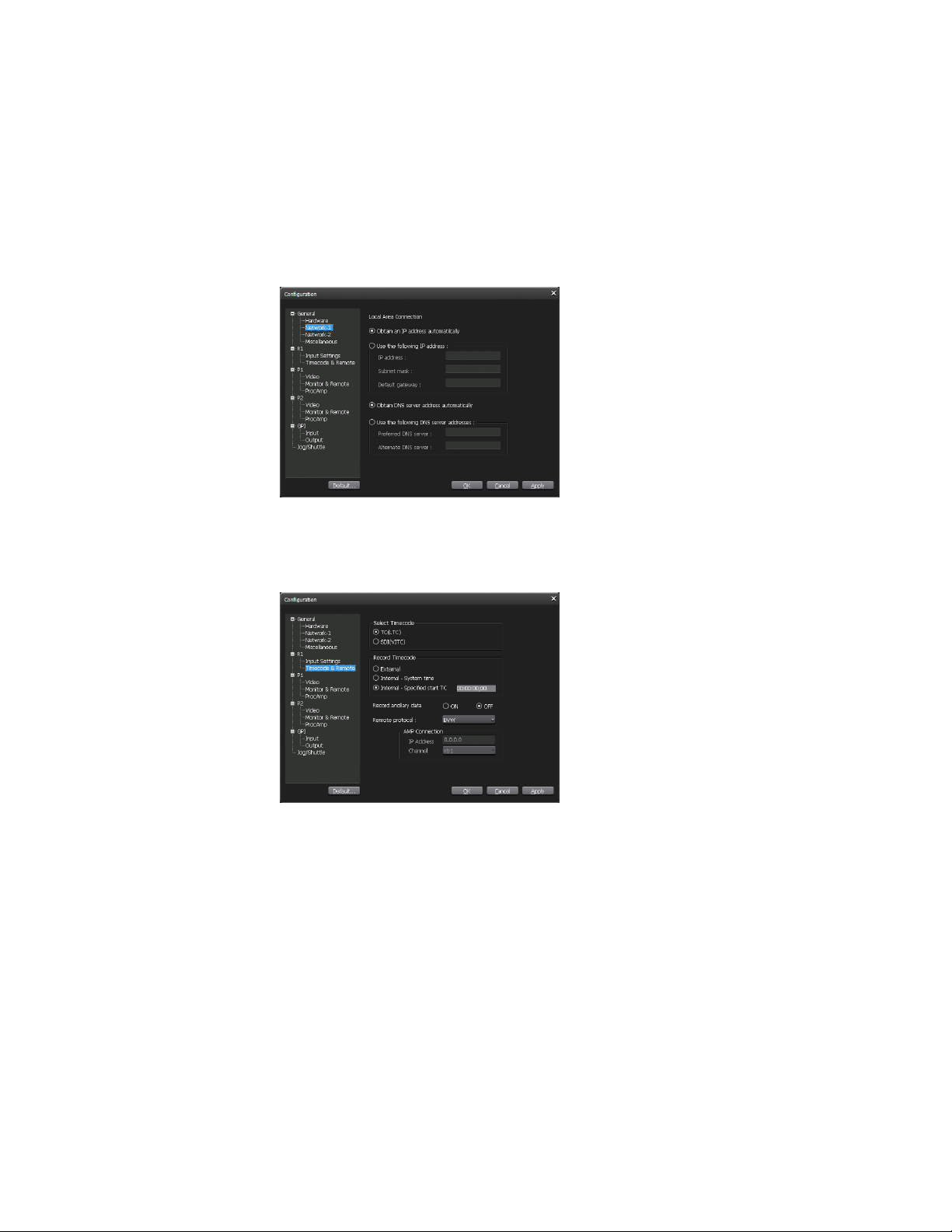
User Manual ― Remote Control(SP1) ―
Cautions
(1) It is prohibited to copy a part or all of this product without prior permission.
(2) Thecontentsorspecicationsofthisproductmaybechangedwithoutprior
notice.
(3) We have prepared the contents of this product to the best of our ability;
however if you have any questions about the contents, or if there are any errors
ormissingitems,pleasecontactGrassValley.
(4) Howeverwedonottakeanyresponsibilityformalfunctionsarisingfromuse,
irrespective of the points outlined in (3).
(5) Irrespectiveofwhetheritwasduetoausageerror,GrassValleytakesno
responsibilityforextraordinary,incidentalorderivativeclaims,includingthose
forlostearningsgeneratedbytheapplicationofthisproduct.
(6) Itisprohibitedtoanalyze,reverseengineer,decompileordisassembleanyof
theitemsincludedwiththisproduct,includingthesoware,hardwareand
manual.
(7) MicrosoandWindowsareregisteredtrademarksoftheMicroso
Corporation, USA.
(8) DVCPROHDisthetrademarkofthePanasonicCorporation.
(9) HDVandHDVlogosarethetrademarksofSonyCorporationandVictor
CompanyofJapan,Limited(JVC).
(10)
Otherproductnamesorrelatedbrandnamesaretrademarksorregistered
trademarks of their respective companies.
About this manual
The screens used as examples in this manual are those of the development•
stage,sotheymayvaryfromthoseinthenalproduct.
If there are any variations between the explanation in this manual and the•
actualapplicationmethod,priorityisgiventotheactualapplicationmethod.
Thismanualiswrienforpeoplewhohaveabasicknowledgeofhowtousea•
computer. If there are no special instructions, perform the same operation as a
normal computer operation.
In this manual, the system of the T2 is called "Workstation".•