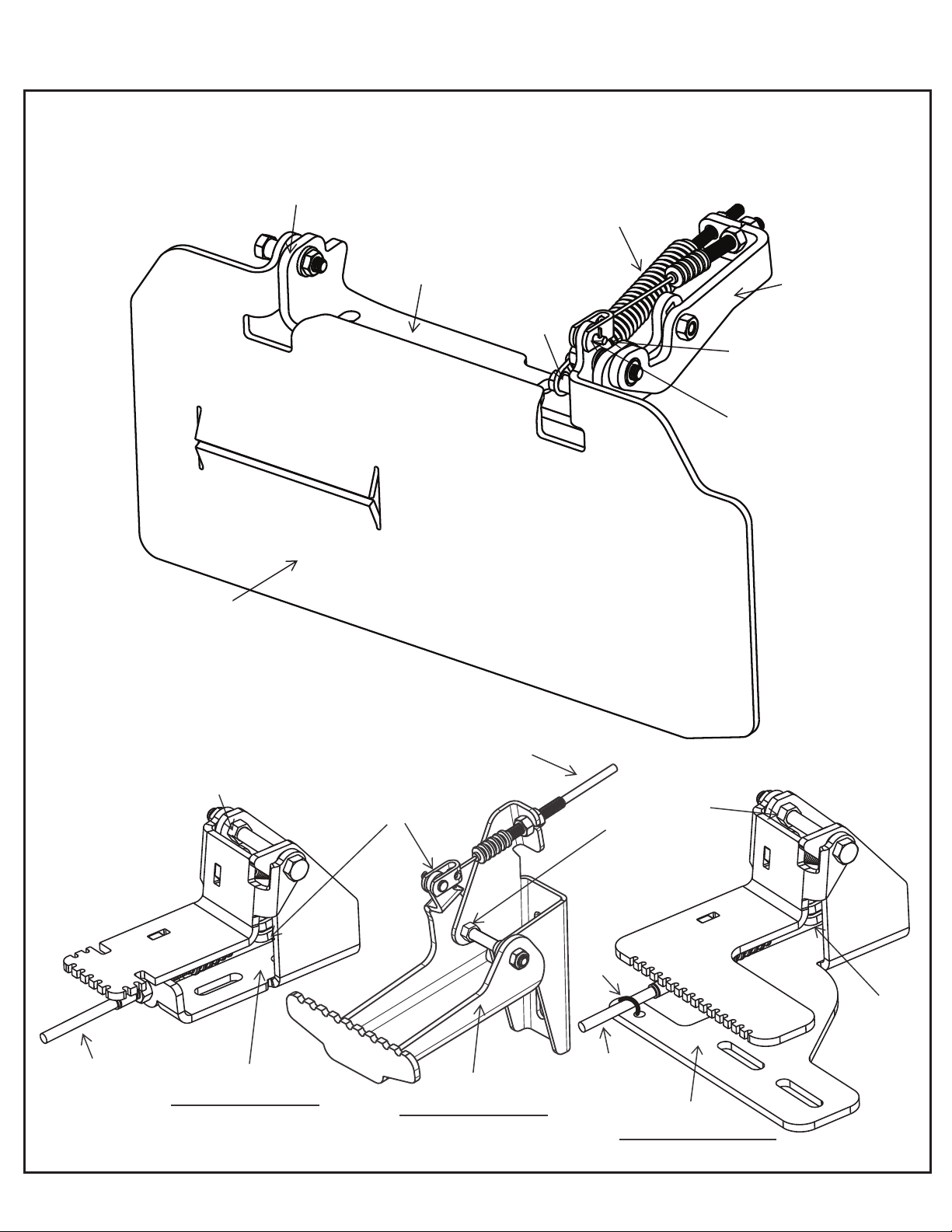
PEDAL END
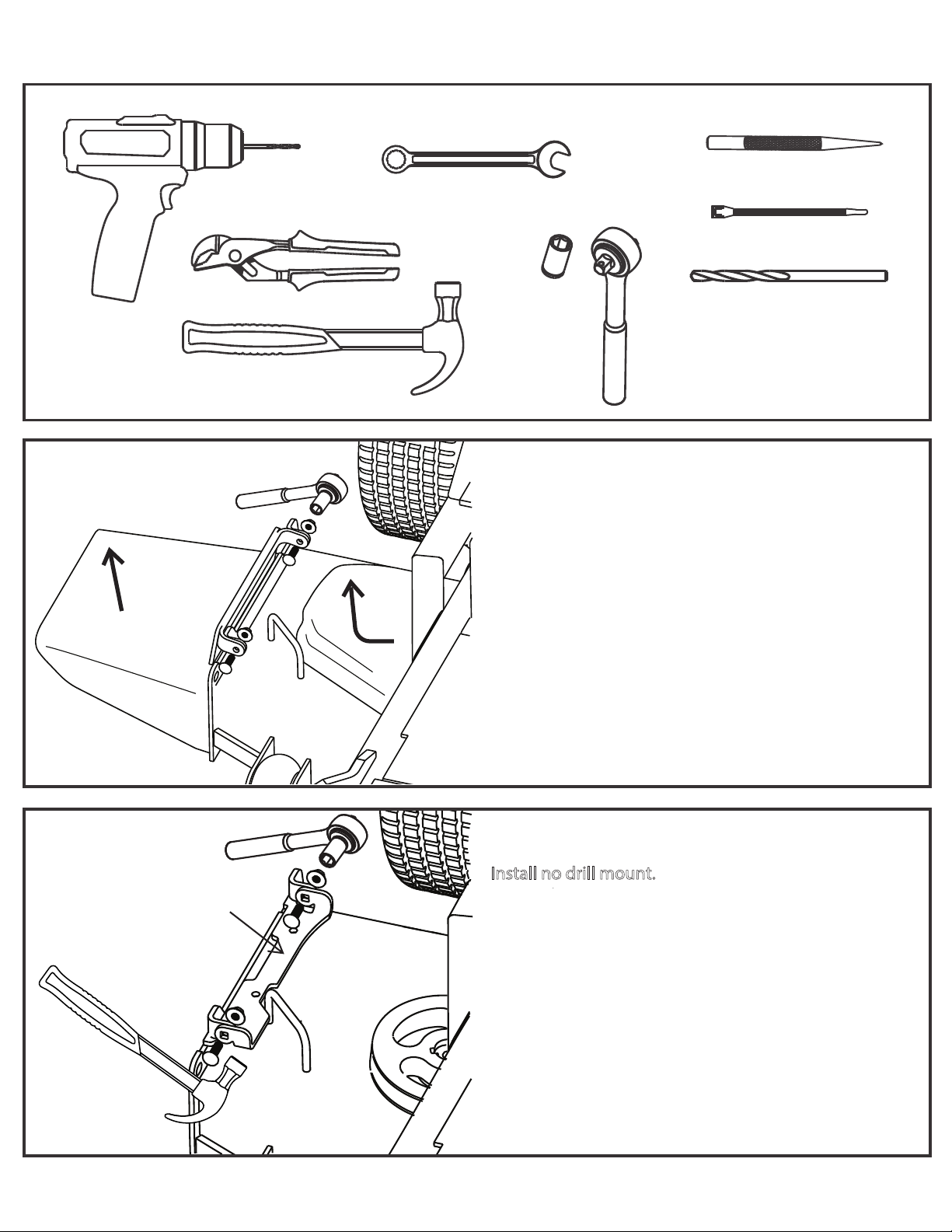
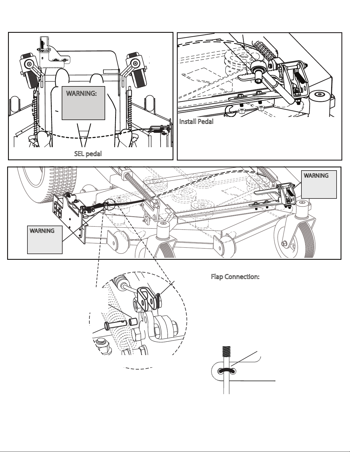
(Cable Installaon, step 1 and 4, AREAS TO
PAY PARTICULAR ATTENTION TO, Recommended cable roung, WARNINGS)
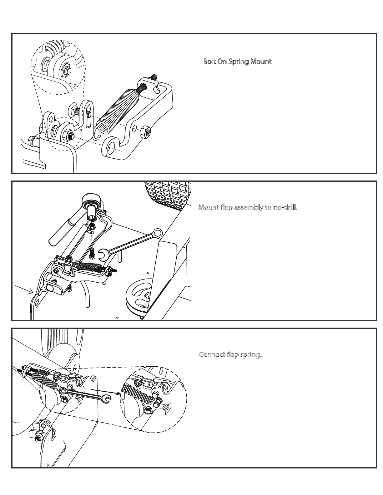
(Recommended cable roung, SECURE
WITH CABLE CLAMP/ZIP TIE)
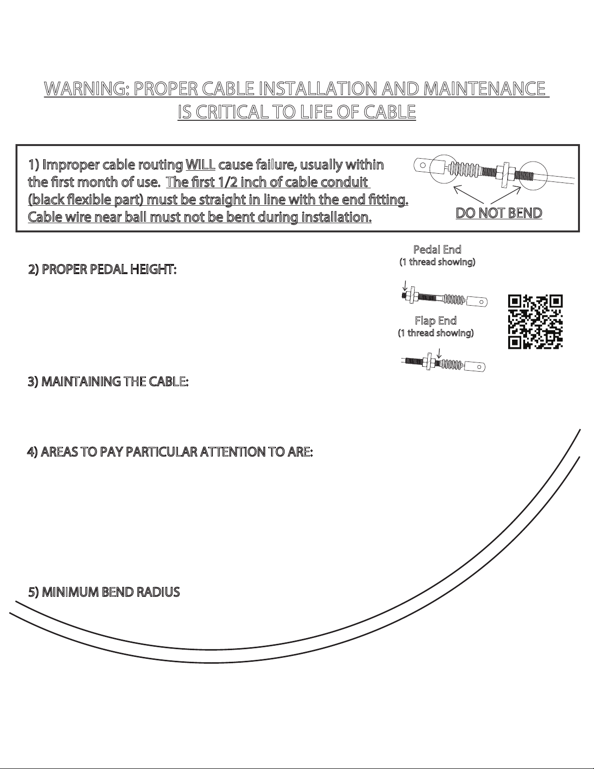
Cable Installaon, step 2,
PROPER PEDAL HEIGHT)
(Cable Installaon, step 3, MAINTAINING THE CABLE)
FLAP END
(Cable Installaon, step 1 and 4, AREAS TO
PAY PARTICULAR ATTENTION TO, page 6 installaon guide, WARNING)
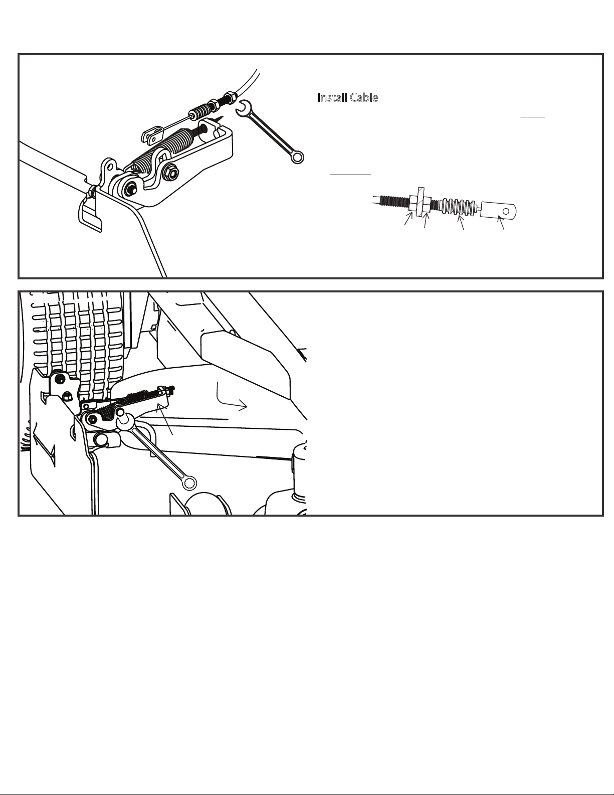
ROUTING
(Cable Installaon, step 4, AREAS TO PAY PARTICULAR
ATTENTION TO)
(Cable Installaon, step 5, REFERENCE 6” RADIUS)
(See recommended cable roung)
GrassFlap.com Phone: (502)594-3546 6