Graviton LPD-1 User manual

User’s Manual
PD Series
O/E CONVERTER
Model
SPD-1 850 LPD-1
SPD-2 850 LPD-2
Graviton INC
https://www.graviton.co.jp/index_En.html
Page 1
Contents of this package
The contents of this package are listed below.
Please contact immediately the shop you purchased this product, if there is any
missing item s found.
①②③
④
①O/E converter ④User’s Manual(this manual)
②Power Cable Assembly
③Auxiliary Power Connector
◇Please keep original packaging, in case of re-shipping.
Page 3
Introduction
Thank you for purchasing PD Series O/E Converter.
PD Series is Optical to Electric signal converter and has following feature.
・SPD-1 850:500mV/mW SPD-2 850:1000mV/mW (@ 850nm Wave Length, 50/125
GI Fiber)
LPD-1:500mV/mW LPD-2:1000mV/mW (@ 1300nm Wave Length, 50/125 GI Fiber)
・Wide Frequency Range
DC~1200MHz Flatness +0.5 –3.0[dB electrical] SPD-1、SPD-2
DC~1500MHz Flatness+0.5 –3.0[dB electrical] LPD-1、LPD-2
・Standard FC optical connector
(Optional SC, F05, SMA, and ST connector are also available.)
・Standard BNC plug
Able to connect directly to an oscilloscope, a spectrum analyzer etc.
・Able to get DC power from instruments through included Power Cable Assembly.
It is not guaranteed that power cable corresponds to all instruments.
・Able to use for instrumentation of lightwave products, optical links or
other various applications.
Please read this user’s manual carefully and use it appropriately according
to this manual, will make this product useful for development of light wave
equipments, lightwave communication converter or other various
applications.
◇Do not re-produce or re-publishing a part or all this manual without
written permission from Graviton Inc.
◇This manual is subject to change without notice.
◇Please follow exporting regulations/rules in individual countries when
exporting this product to other countries.
Page 2
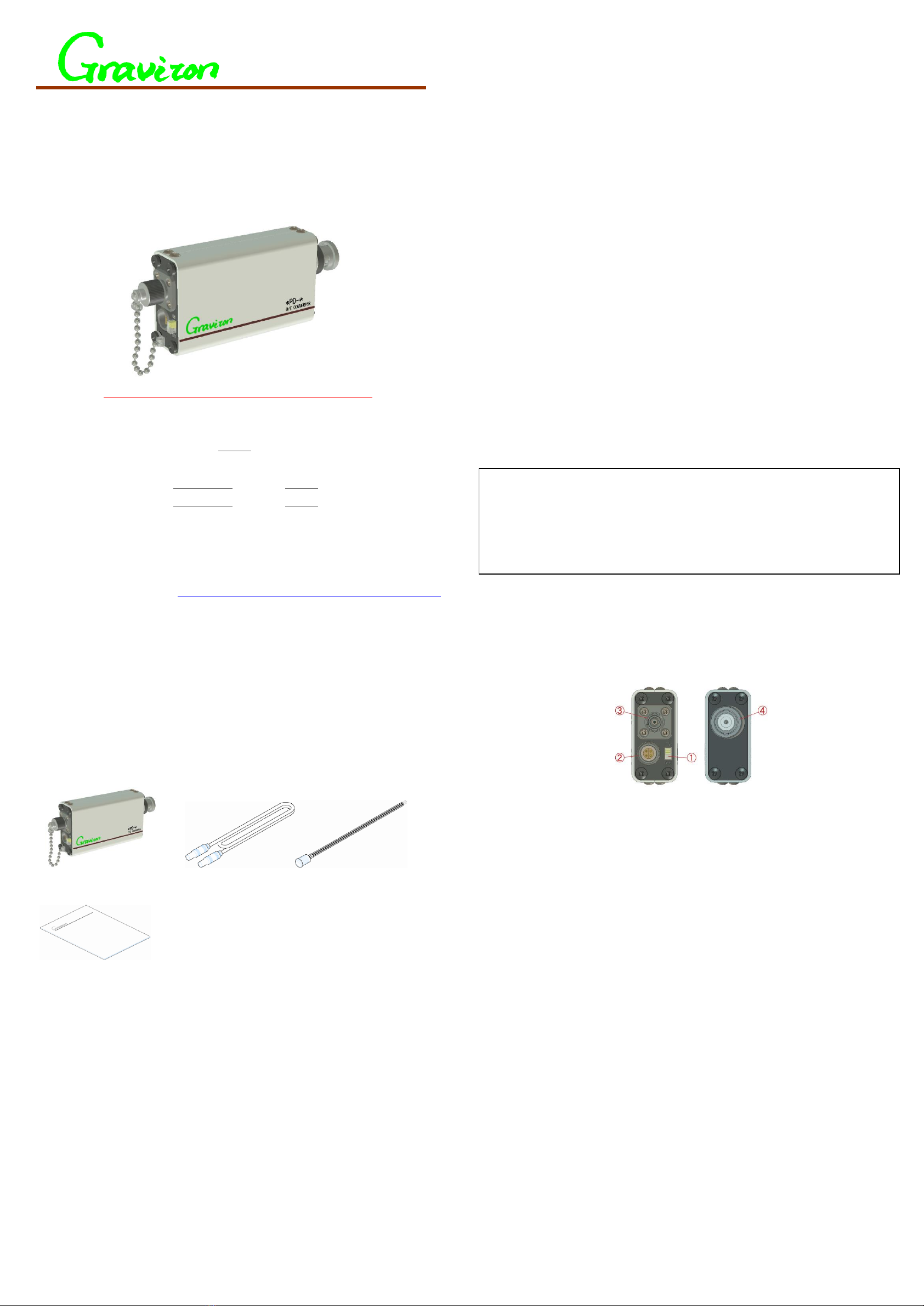
Front and rear panel view
①Power switch
This switch is for controlling power. Please on/off this switch after
connecting power cable assembly to power connector(②) also keep this switch
off when not in use.
②Power input connector
The power can be supplied from probe power connector that equipped with an
instrument through the Power Cable Assembly. Or, alternately, external
regulated power supply (not included) can be used through the Auxiliary Power
Connector. Power supply voltage for PD series is±15[V]. Applying over and/or
wrong polarity may cause permanent damage. Please refer the specification
in page 7 for current consumption and page 5 for the detail of the power
connection.
③Optical signal input connector
Light signal supplied through this FC connector is up to -1[dBm] for SPD-1
850・LPD-1 and up to -4[dBm] for SPD-2 850・LPD-2. Please do not apply 10dBm
or higher light signal. It may cause permanent damage.
④Electrical signal output connector
50[Ω] input impedance with wide frequency range instruments is suitable to
observe light signal. Recommended to use wider frequency range instruments
to withdraw full spec.(DC~1200MHz SPD-1 850・SPD-2 850, DC~1500MHz LPD-1・
LPD-2)
Page 4
Please read this manual carefully before use

0.2
0.4
0.6
0.8
1
1.2
300 400 500 600 700 800 900 1000
Set up
1. First of all, connect the O/E converter to input connector of an instrument.
Conversion connector may be required, if the instrument has no BNC jack.
2. Confirm power switch on the O/E converter is off then connect Power Cable
Assembly supplied. Other side of the Power Cable can be connected to the
instrument, if probe power connector is equipped. Please refer page 6 for
connecting external power supply, if the instrument has no probe power
connector.
3. Turn on the power switch.
4. Connect fiber connector to the O/E converter and adjust voltage and sweep
time of the instrument observe the light signal. Also make sure 50[Ω]
impedance is selected on the instrument.
Page 5
Specifications
Item Test Condition SPD-1 850 SPD-2 850 LPD-1 LPD-2
OE Device Si Si InGaAs InGaAs
PIN PD PIN PD PIN PD PIN PD
Peak Sensitivity Wavelength 760nm 760nm 1550nm 1550nm
Wavelength Range More than 1/5 320nm ~380nm ~900nm ~950nm ~
of peak sens. 1000nm 1000nm 1650nm 1650nm
Conversion Gain 50GI Fiber 500mV/mW 1000mV/Mw 500mV/mW 1000mV/mW
@850nm @850nm @1300nm @1300nm
Acceptable Core Diameter Less than Less than Less than Less than
0.8mm 1.0mm 0.08mm 0.5mm
Acceptable Fiber NA Less than Less than Less than Less than
0.2 0.25 0.2 0.25
Frequency Bandwidth -3dB electrical DC~1.2GHz DC~1.2GHz DC~1.5GHz DC~1.5GHz
Maximum Optical Power for 400mV Out -1dBm -4dBm -1dBm -4dBm
Proper Signal Output @850nm @850nm @1300nm @1300nm
Wideband Noise Voltage Up to 12.4GHz Less than Less than Less than Less than
1.3mVrms 1.9mVrms 0.8mVrms 1.8mVrms
Noise Equivalent Power 850nm, (1300nm) Less than Less than Less than Less than
-26.0dBm -27.3dBm -27.9dBm -29.2dBm
Output Offset Voltage No Input Signal Within Within Within Within
+/- 0.5mV +/- 0.5mV +/- 0.5mV +/- 0.5mV
Output Impedance 50ohms 50ohms 50ohms 50ohms
Input Optical Connector FC FC FC FC
Output Coax Connector BNC Plug BNC Plug BNC Plug BNC Plug
Supply Voltage +/-15V DC +/-15V DC +/-15V DC +/-15V DC
Supply Current +150mA/-50mA +150mA/-50mA +150mA/-50mA +150mA/-50mA
Physical Dimension[mm] 93x44x21 103x44x21 93x44x21 103x44x21
Weight[g] 110 130 110 130
Operational Temperature +5[℃]~+35[℃] Storage temperature -20[℃]~+50[℃]
(This specifications are subject to change without notice.)
Page 7
Connecting External Power Supply
1.An external power supply is necessary, if an instrument going to use has no
probe power output. The requirements for the power supply are regulated±15[V]
±5[%]and capable of supplying more than 150[mA] current with low ripple and
noise. And connect as following figure.
Wrong power supply connection may cause permanent damage on the O/E converter. Please
make sure the connection as RED Cable for Positive terminal, Black Cable for Ground
Terminal and Blue Cable for Negative Terminal.
2. Panel cutout size is as following to mount the Auxiliary Power Connecter on
a panel, if necessary. Maximum allowable thickness of the panel is 5mm.
Page 6
The Spectral Sensitivity curve of SPD-1 850, SPD-2 850
The Spectral Sensitivity curve of LPD-1, LPD-2
Page 8 No.20220831-01
0.2
0.3
0.4
0.5
0.6
0.7
0.8
0.9
1
1.1
1.2
1.3
900 1000 1100 1200 1300 1400 1500 1600 1700
Wave Length【nm】
LPD-1
LPD-2
Wave Length【nm】
SPD-1 850
SPD-2 850
(Reference point is 1 at 850nm)
(Reference point is 1 at 1300nm)
+ 1 5V (R E D )
G N D (B LA CK )
-1 5 V (B LU E )
Contact to : Graviton Inc.
1-8-1 Kasuga-cho, IRUMA-SHI, SAITAMA, 358-0006 JAPAN
TEL:+81-4-2966-0816 FAX:+81-4-2966-0817
“GRAVITON” is trade mark of Graviton lnc. in Japan.
Copyright 2006 by Graviton Inc. All right reserved.
Never reproduce or republish without written permission.
This manual suits for next models
4
Other Graviton Media Converter manuals
Popular Media Converter manuals by other brands

Xtreme Power Conversion
Xtreme Power Conversion XPD0215SL User and installation manual

MRC
MRC 0001644-2 quick start guide

Miranda
Miranda SDM-771p Guide to installation and operation

National Instruments
National Instruments GPIB-PRL user manual

MuxLab
MuxLab 500054 Quick installation guide

Lenz
Lenz Digital plus GOLD maxi Information