-- Links to each page --
* Overview
* Precautions
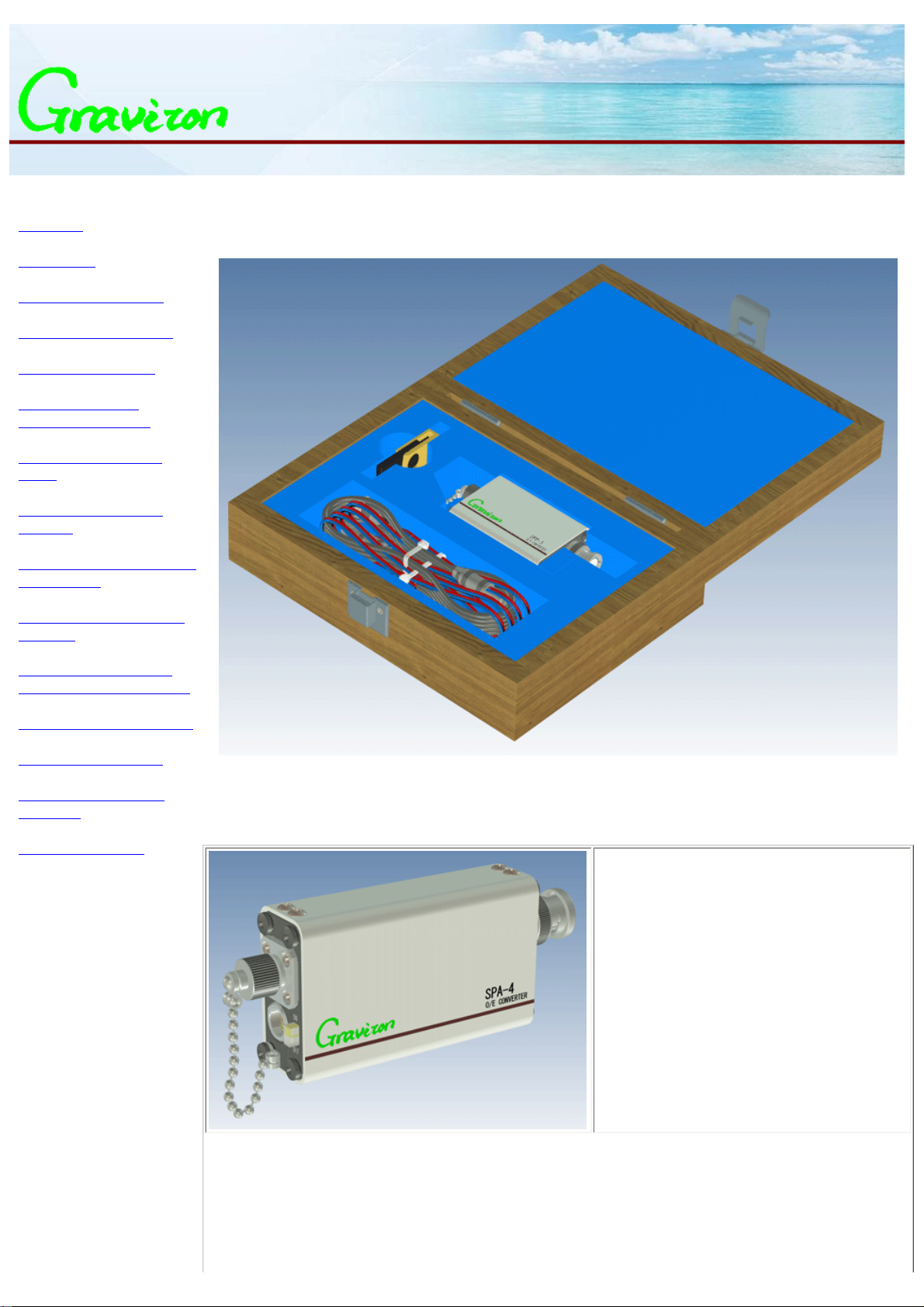
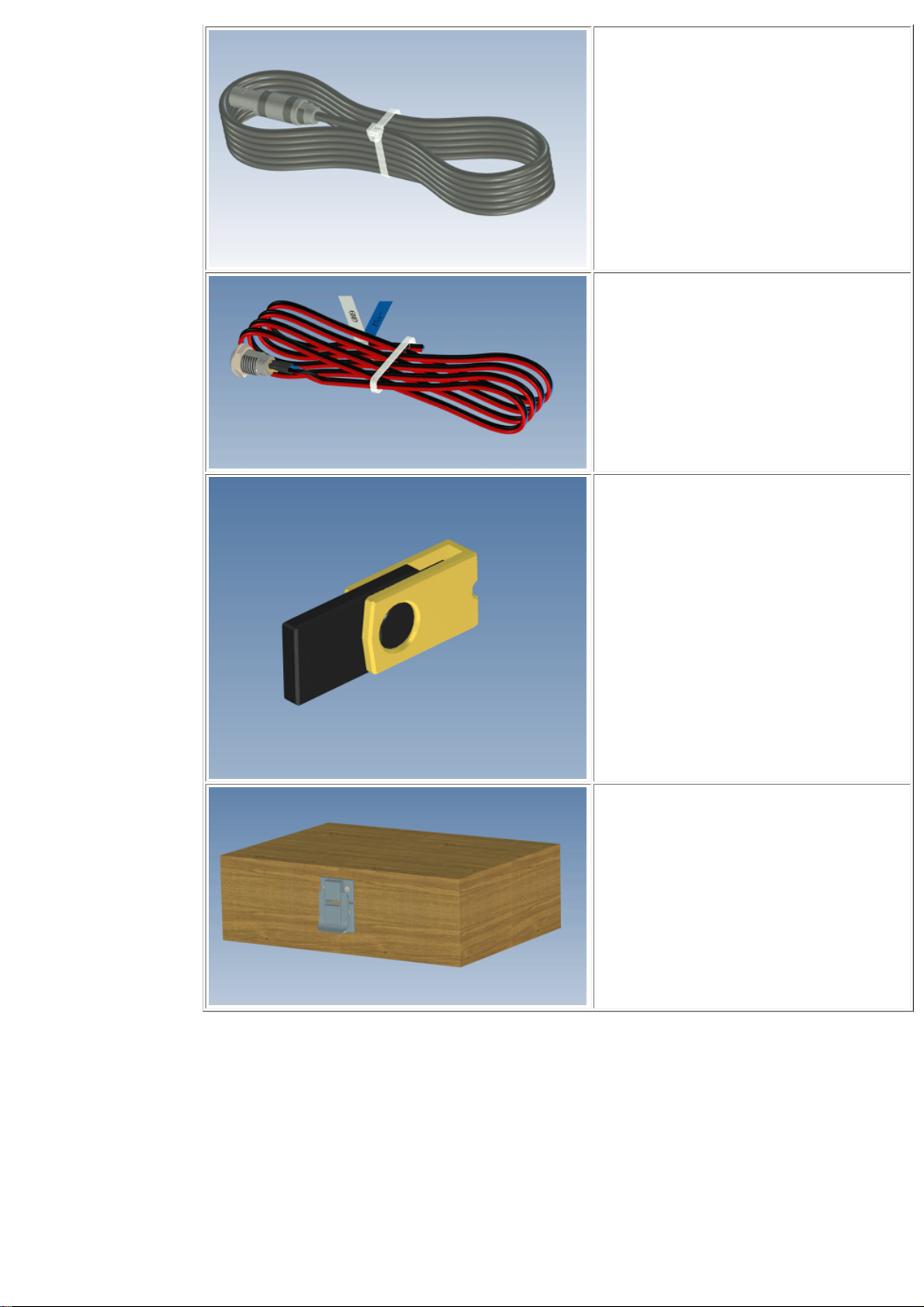
* Contents of the package
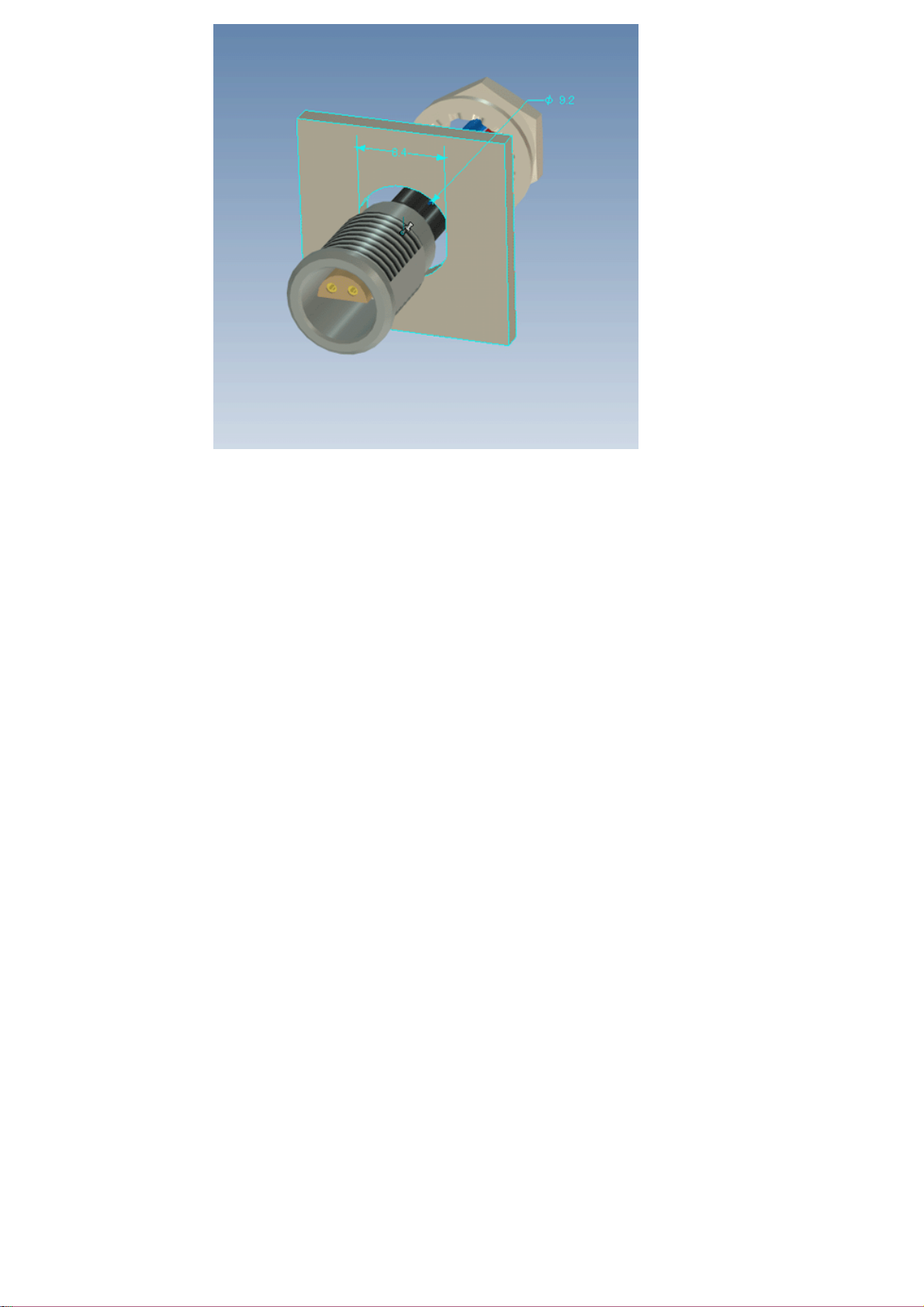
* Part names and functions
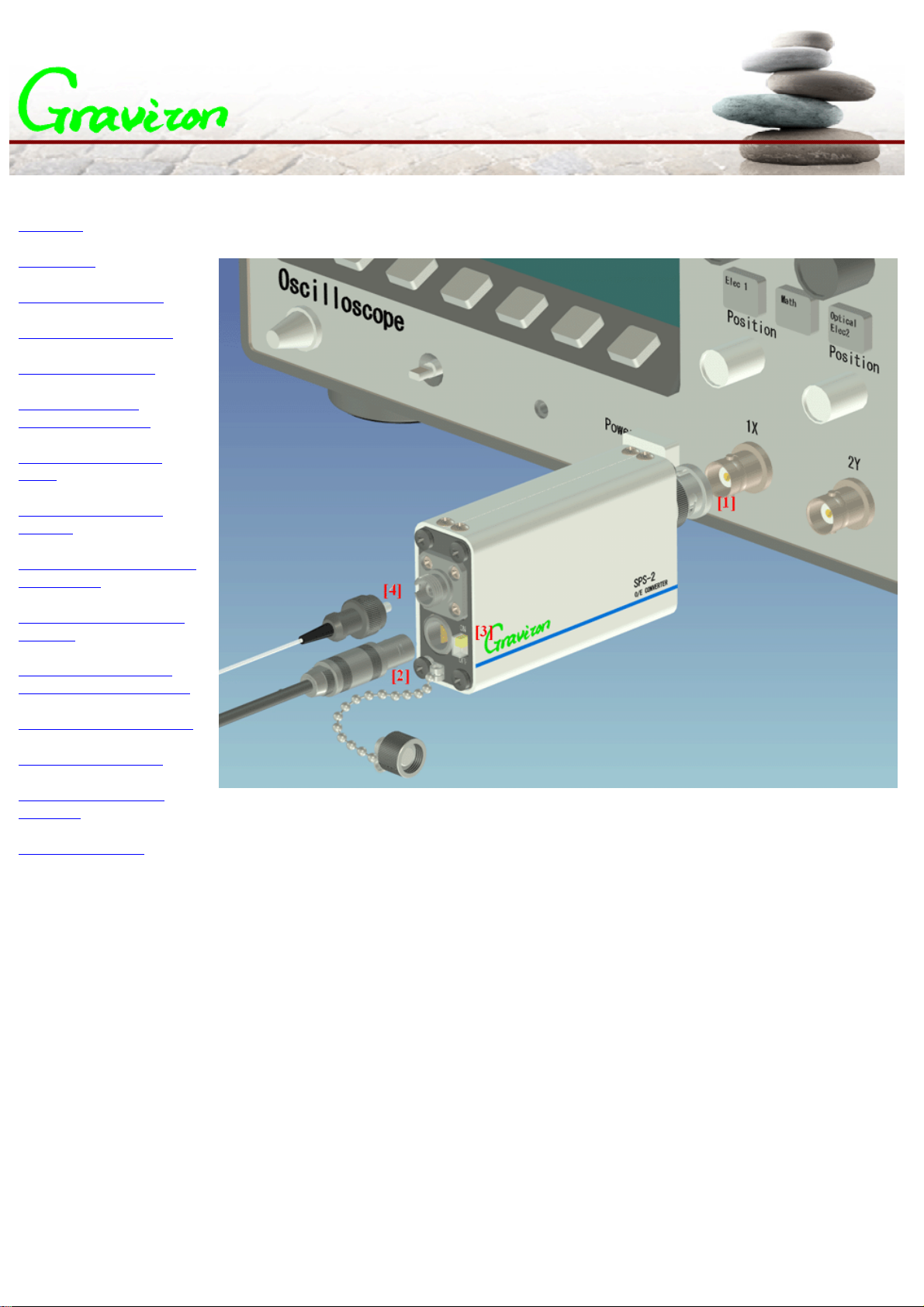
* Mount and connection
* Shipment data and
measurement examples
* Comparison of the lens
system
* Comparison of the step
responses
* Comparison of the frequency
characteristics
* Comparison of the spectral
sensitivity
* Frequency characteristic
dependence on the wavelength
* Specifications for each model
* Options and accessories
* Calibration and Export
certificates
* Contact information
Overview
Graviton's O/E converter allows the measurement of the
optical signal, by attaching to the input terminal of the
customer's measurement equipment.
* Small size, light weight, easy to attach
* Large detection diameter and NA
* Covers wide band from DC to GHz
* Many types of optical connector option
Read this instruction manual carefully before use.
Selection guide
Graviton offers a variety of O/E converter models, by the requested features of; Wavelength range, Reference
wavelength, Acceptable core diameter, Input NA, and Conversion frequency bandwidth.
* Converter for visible light (Si photodetector is used)
Model name Wavelength range Reference
wavelength Sensitivity Max. core
diameter Max.NA Bandwidth tr/tf
SPD-1_650nm 320nm〜1000nm 650nm 500V/W 0.8mm 0.2 DC〜1.2GHz 290ps
SPD-1_850nm 320nm〜1000nm 850nm 500V/W 0.8mm 0.2 DC〜1.2GHz 290ps
SPD-2_650nm 380nm〜1000nm 650nm 1000V/W 1.0mm 0.25 DC〜1.2GHz 290ps
SPD-2_850nm 380nm〜1000nm 850nm 1000V/W 1.0mm 0.25 DC〜1.2GHz 290ps
SPD-3 380nm〜950nm 850nm 500V/W 0.5mm 0.25 DC〜2.0GHz 190ps
SPD-4 380nm〜950nm 850nm 300V/W 0.5mm 0.25 DC〜3.0GHz 150ps
SPA-2_650nm 400nm〜1000nm 650nm 1000V/W 1.0mm 0.5 DC〜1.0GHz 370ps
SPA-3 380nm〜950nm 850nm 500V/W 0.25mm 0.5 DC〜2.0GHz 190ps
SPA-4 380nm〜950nm 850nm 300V/W 0.25mm 0.5 DC〜3.0GHz 150ps
SPS-1_10KV/W 320nm〜1000nm 850nm 10KV/W 0.8mm 0.2 DC〜100MHz 3.6ns
SPS-1 100KV/W 320nm〜1000nm 850nm 100KV/W 0.8mm 0.2 DC〜15MHz 28ns
SPS-2_10KV/W 400nm〜1000nm 850nm 10KV/W 1.0mm 0.5 DC〜100MHz 3.6ns
SPS-S_100KV/W 400nm〜1000nm 850nm 100KV/W 1.0mm 0.5 DC〜15MHz 28ns
* Converter for long wavelength (InGaAs photodetector is used)
Model name Wavelength range Reference
wavelength Sensitivity Max core
diameter Max.NA Bandwidth tr/tf
LPD-1 900nm〜1650nm 1310nm 500V/W 0.08mm 0.2 DC〜1.5GHz 250ps
LPD-2 950nm〜1650nm 1310nm 1000V/W 0.5mm 0.25 DC〜1.5GHz 250ps
LPS-1_20KV/W 900nm〜1650nm 1310nm 20KV/W 0.08mm 0.2 DC〜100MHz 3.5ns
LPS-2_20KV/W 950nm〜1650nm 1310nm 20KV/W 0.5mm 0.25 DC〜100MHz 3.5ns
Instruction manual of O/E converter - Overview