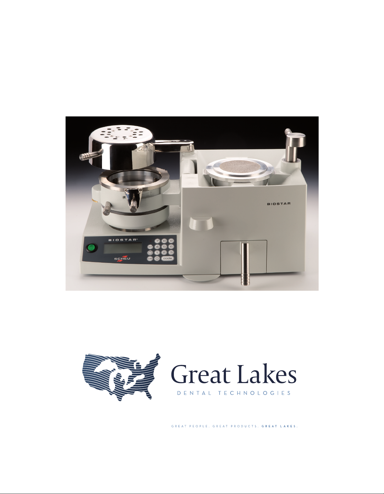
Heating Element: Found on left side of
machine, swivels from front to back and is used
to soften thermal-plastics.
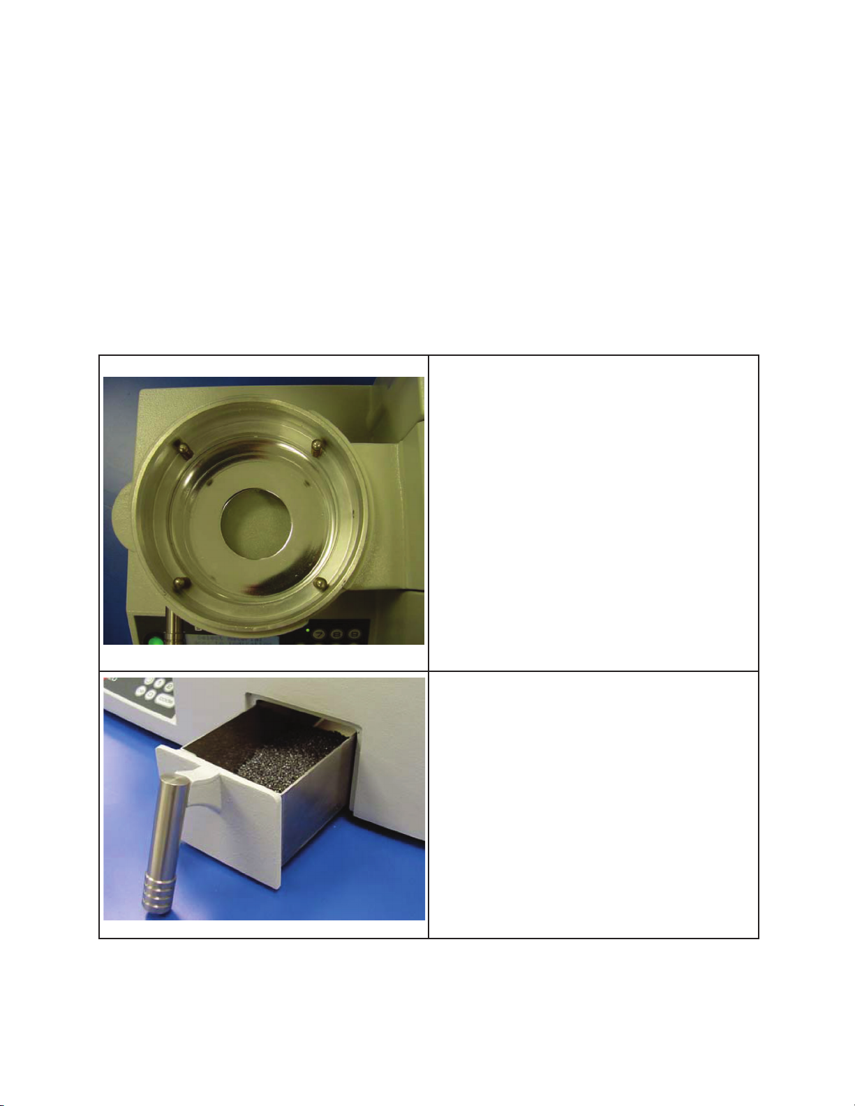
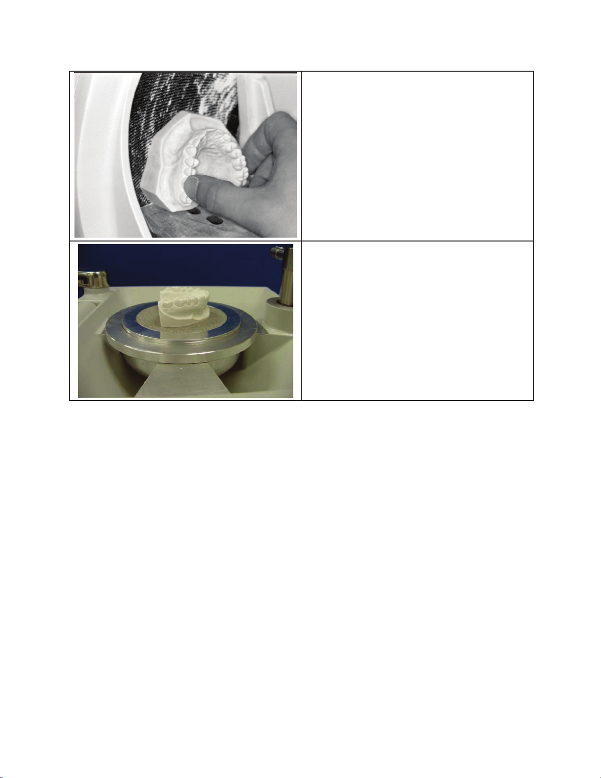
Pressure Chamber: Compartment that the
thermal-plastic material is held, heated, and
formed over a dental model.
Locking Handle: Holds chamber in molding
position and allows air pressure to enter
chamber.
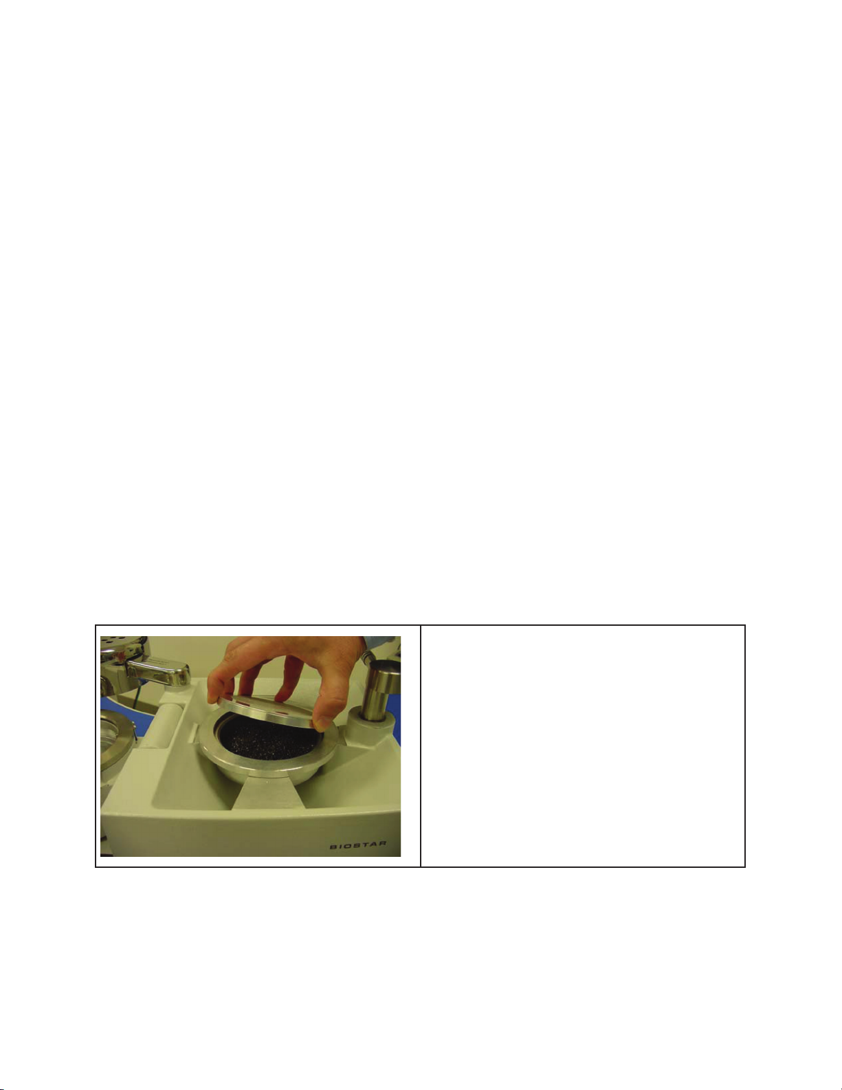
Clamping Frame: Secures thermal-plastic to
chamber.
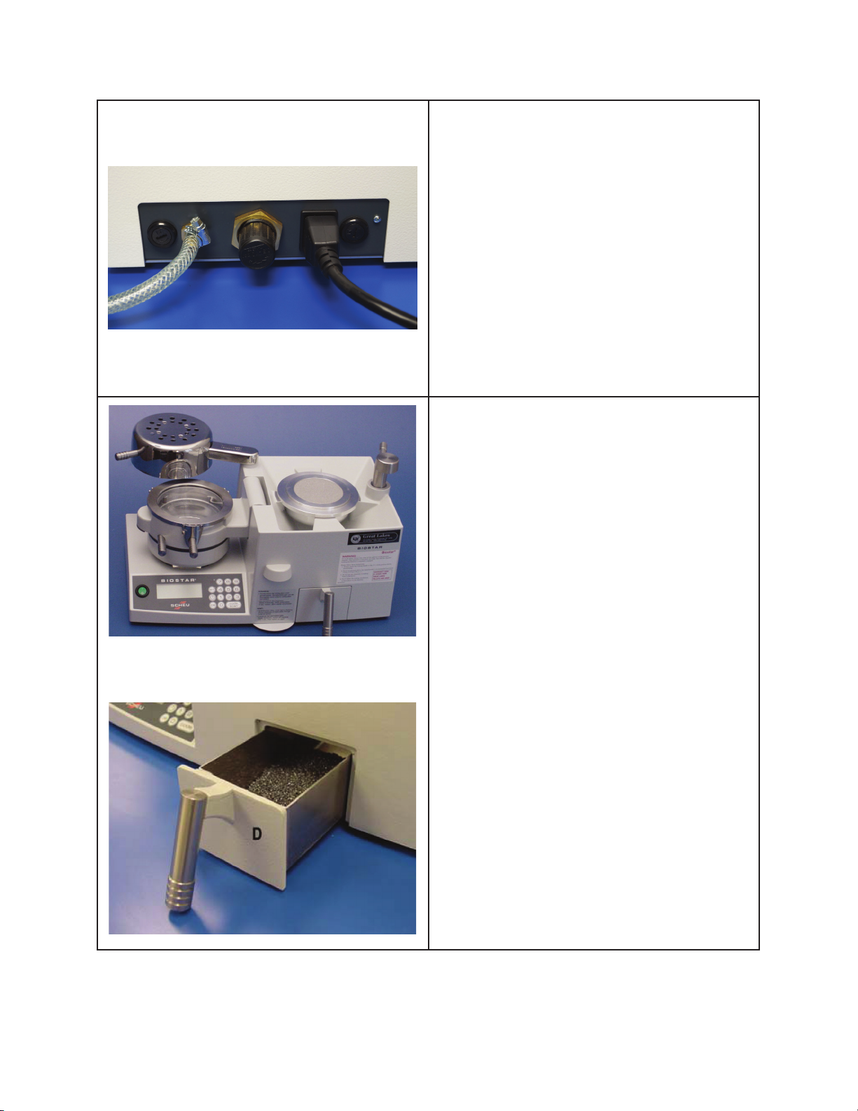
Pellet Drawer: Contains overow of pellets.
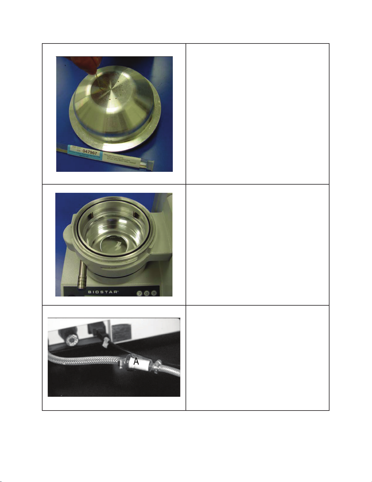
Bar Code Scanner: Automatically enters the correct
processing information for the thermal-plastic.
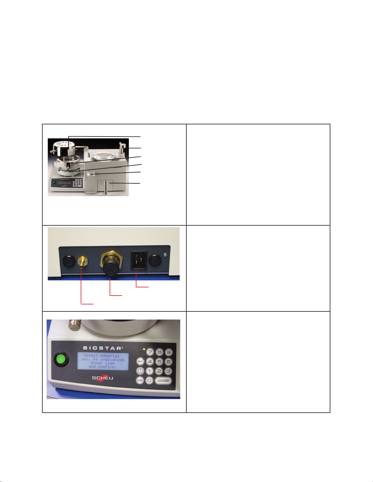
Plug with Fuse: Built-in plug with a two 8-amp
fuse compartment.
Pressure Controller: Air pressure adjustment
dial to control the amount of pressure that is
used within the Biostar.
Compressed-air Connection: Connects to
laboratory air pressure source.
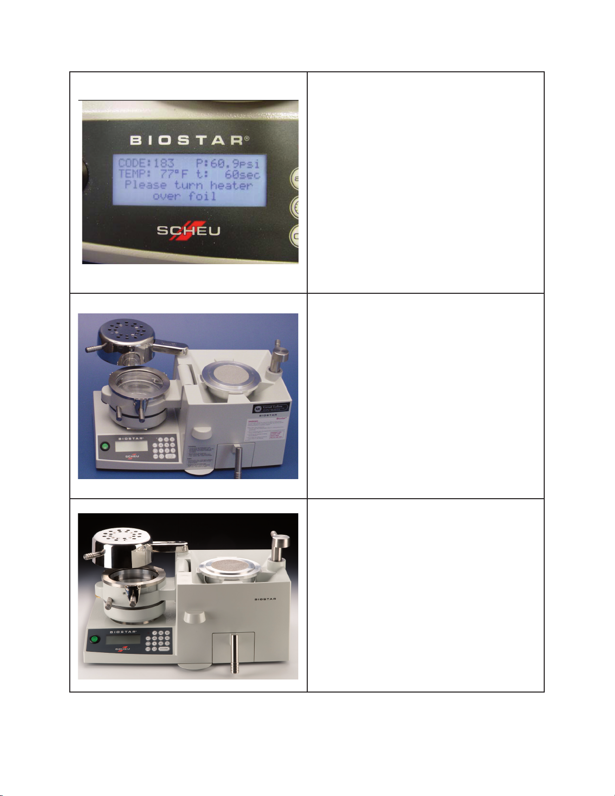
On/Off Switch: Power switch.
Code Button: Programs heating and cooling
operating times for material heating and
pressure forming.
Air Button: Removes air pressure from
chamber.
CE Button: Erases information placed in
memory.
Time Button: (Illustration of clock) Allows
operator to manually program heating and
pressure molding times, separately.
After inspecting the items, remove all packing material, and position the Biostar unit on the
laboratory bench. To prevent machine malfunctions as a result of excessive dust, do not place
the unit near etcher catchers, micro etchers, or any area where extensive plasterwork will
occur. The air source should be within reach of the machine using the high-pressure hose as a
reference guide. Do not place the pressure line under the heater along the benchtop. The air
pressure should be capable of supplying a minimum of 87 psi. to the Biostar.
The following information provides a brief description of the computerized Biostar’s basic
components.
2
plug with fuse
compressed-air connection
pressure controller (regulator)
Heater
Locking Handle
Clamping Chamber
Pressure Chamber
Bar Code Scanner
Pellet Drawer