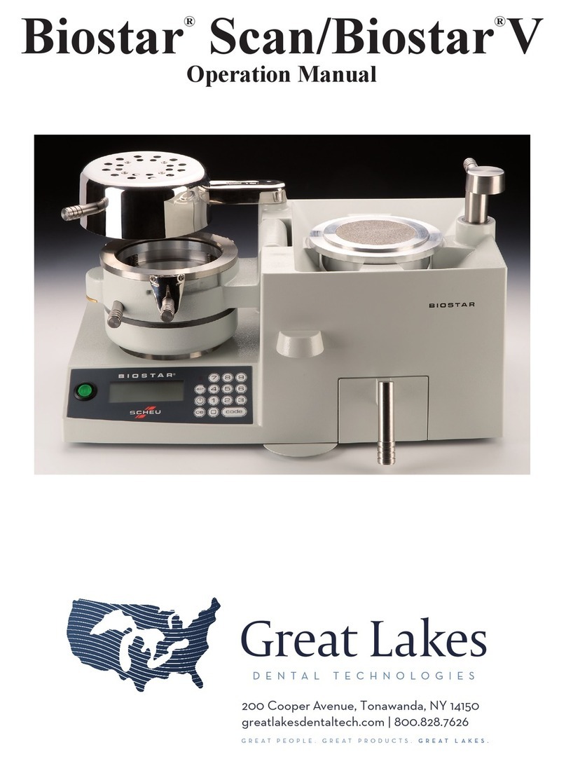
Great Lakes MINISTAR S User manual

GREATPEOPLE. GREATPRODUCTS. GREATLAKES. greatlakesdentaltech.com
MINISTARS®
OPERATIONMANUAL
GREATLAKESDENTALTECHNOLOGIES
For fabrication videos, tips and techniques,
visit greatlakesdentaltech.com/techniques.
GLO016 BrandedTemplates_85x11_MinistarCover.indd 1 11/14/18 3:09 PM

2
MiniSTAR
S
with Scan Technology
A smaller, less expensive version of the Biostar was introduced in 1991 called the MiniSTAR. The compact design
utilizes the same principles as the computerized Biostar, with reduced pressure and a modified timing mechanism
used for heating and pressure-cooling cycles. In 2011, a barcode scanner was added to the MiniSTAR S. This
feature automatically enters the correct processing information for the thermal-plastic material.
®
Installation
Before removing the machine and its components from the shipping box, determine the location for the MiniSTAR S
in the laboratory. The machine’s size and weight are outlined above. Make sure sufficient workspace around the
machine is available and that nothing will interfere with operation of the heating element.
Reminder: Keep any flammable material away from the heating element.
The shipping box contains:
•MiniSTAR S unit
•Pellet drawer
•Clamping frame
•Model platform
•High pressure hose with hose clamps and air filter
•Container of pellets
•Pellet brush with magnet
•Replacement air filter
After inspecting the items, remove all packing material, and position the MiniSTAR S unit on the laboratory bench. To
prevent machine malfunctions as a result of excessive dust, do not place the unit near etcher catchers, microetchers,
or any other dust or water-generating equipment. The air source should be within reach of the machine using the
high-pressure hose as a reference guide. The air pressure should be capable of supplying a minimum of 60 psi to the
unit.
Technical Data:
•Voltage 115V (AC) - 50/60 Hz
•Power 750 W
•Pressure 60 psi / 4 bar
•W x D x H 17.25”x 14.25”x 8.25”
•Weight 31lbs / 9.07kg

3
Infrared Heater: Found on left side of unit, swings from back of machine (rest position), forward over
thermal plastic held on the chamber.
Control Panel: Contains operating controls including electrical power switch, keypad operation input
buttons, air pressure verification button, and digital operating viewing panel.
Locking Handle: Locks chamber onto pellet cup/platform and switches air pressure on.
Barcode Scanner: Automatically enters the correct processing information for the thermal plastic.
Pellet Cup: Used in every molding process and is fixed on the MiniSTAR S table. The pellet cup
holds the dental model, pellets, and platform.
Platform*: Circular plate that is placed on the inner lip of the master pellet cup,
to be used in place of pellets.
Pellet Drawer: Removable front compartment that holds unused pellets.
Pressure Chamber: Thermal plastic is held and air pressure incorporated for molding.
Locking Ring Clamp: Circular metal clamp that secures material to pressure chamber.
C
E
F
G
B
A
I
H
D
A
G
H
F
E
D
C
B
AInfrared Heater
BControl Panel
C Locking Handle
DBarcode Scanner
EPellet Cup
FPellet Drawer
GPressure Chamber
HLocking Ring Clamp
IPlatform*
Front View
I
The basic components of the MiniSTAR S with Scan Technology include:

4
The basic components of the MiniSTAR S with Scan Technology include:
Back View
ACompressed Air Supply
BPressure Regulator
C Fuse Holders
DPlug
Back View
A
Compressed Air Supply
B
Pressure Regulator
C
Fuse Holders
D
Plug
C
A
BD
Control Panel
AON/OFF Switch
BDigital Panel
C Duo LED Light
DTime Input Button
E Air Pressure Verification Button
F Blue LED Light
G Code/Scan Button
On/Off Switch: Supplies electricity to operate the machine
Digital Panel: Indicates heating/cooling time and measures air pressure and lamp temperature
Duo LED: The green LED indicates operating mode (heater ready) and the red LED
indicates heating mode (heating started)
Time Input Button: Heating times can be programmed manually on the numeric keypad
Air Pressure Verification Button: Used for air pressure verification/depressurization of the chamber
Blue LED: Indicates chamber pressurized (continuous light) and depressurized (flashing light)
Code/Scan Button: Activates the barcode scanner and 3-digit operation barcode command
Compressed Air Supply: A ribbed air valve to clamp the air-pressure hose to the machine
Pressure Regulator: Dial to increase or decrease air pressure used in the MiniSTAR S
Fuse Holders: Two compartments that house miniature fuses
Plug: Three-prong electrical socket for detachable power cord
ACompressed Air Supply
BPressure Regulator
C Fuse Holders
DPlug
Back View
A
B
C
E
G
D
F

5
1. Plug the electrical cord in the back of the MiniSTAR S (A)
into a three-prong 110v outlet. The fuses are located in the
back of the machine above the electrical connection (B)
(Miniature Fuse: 2x10A LAZY).
2. Connect the MiniSTAR S to the air source using the high-
pressure hose. Slip one end of the hose onto the air valve
(C) of the MiniSTAR S, and slip the other end over the air
pressure line. Secure each end in place with a hose clamp.
Note: Route the electrical cord and pressure
hose away from the heating element.
3. Secure the clamping frame to the pressure chamber by
referencing the clamp handle at a 4-5 o’clock position over
the chamber. Slip the clips of the clamping frame into the
grooves on the outside of the chamber and slide the
clamping handle to the left (blue arrow).
4. With pellets provided, fill cup (D) half full with pellets.
5. Pour remaining pellets in the pellet drawer (E) and
clip it onto the front of the MiniSTAR S table.
6. Place platform on inner lip of the pellet cup, with the
pellet level half full. Make sure the inner lip of the
cup is clear of pellets.
Working pressure of 4 bar (60 psi) is pre-set in the machine. Confirm or
adjust MiniSTAR S air pressure by first turning on the main air source (A).
Release the locking cap on the regulator by pulling it outward (B). Set the
pressure by turning the regulator dial on the back of the machine clock-
wise to increase the pressure, counterclockwise to decrease (C).
Identify the proper pressure by the gauge. Once pressure is set, lock
regulator by pushing the cap in towards the machine. Maximum
pressure is approximately 4 bar, or only what the main line is capable
of supplying.
Reminder: Do Not use material thicker than 5mm within the clamping mechanism.
This may cause the MiniSTAR S to malfunction while pressure is in the chamber. Always
wear safety glasses when using this machine and during all fabrication procedures.
Initial Setup and Use
E
D
B
CA
E
D
A
B
- /+
C

6
Maintenance
A regular maintenance schedule should be followed. Proper maintenance will assure better fabrication results. Refrain
from using water in the MiniSTAR S machine. Water may cause certain components to rust or corrode. When the machine
is not being used, engage the clamping frame to the chamber and position the chamber on the pellet cup. This prevents
lab dust from entering the pellet cup and chamber.
Pellets will become dirty with regular use. Clean pellets by
placing them in a strainer and rinsing with hot water. Spread
pellets on a towel and let air dry before placing them back in
the MiniSTAR S. Check pellets monthly. Discard and replace
pellets in the bottom third of the cup.
Air escape holes are present in the base of the pellet cup and
should be checked monthly to ensure that they remain open.
Use a .036” diameter or smaller wire to open plugged holes.
Clean and inspect top and side of the Adjusting Ring*
every 4-6 months.
• Clean gasket with a soft cloth
• Check potential gasket cuts or irregularities
*Adjusting Ring should move freely in the chamber. If not,
after cleaning, apply a thin coat of Silicone Grease (016-021)
to inner wall of the chamber, 4 spring-loaded adjusting pins,
and outside edge of the adjusting ring (see white arrows).
*Adjusting Ring is assembled from four components:
A.Chamber sealing ring
B. Aluminum ring
C. Side gasket
D. Spring-loaded adjusting pins
A
CB
DD
D
D

7
Check the air filter clamped to air line (white arrow) monthly
for discoloration and/or moisture.
If replacing the filter, turn off the air source and bleed the
high-pressure hose of air. Loosen clamps holding the filter
and slide it off the hose. Position the new filter by referencing
the arrow on the filter case toward the back of the MiniSTAR S.
The heating surface (A) should be parallel to the heating
element (B). Adjust the position of the chamber by turning
the screw (C) located under the chamber support frame with
a small screwdriver.
Clockwise adjustment of the screw lowers the chamber from
the heater, counterclockwise raises the chamber closer to the
heater.
Check the position of the chamber when heating materials.
Operation
Model Preparation
There are three basic functions to operate the MiniSTAR S including:
•Model preparation
•Heating cycle
•Pressure molding process
Prepare models for the thermal-forming process by removing bubbles or filling voids whether using the platform or
pellets. The platform is used when forming soft or thin plastics. Pellets are used when forming thick, less flexible
materials. The pellets prevent the plastic from forming to unwanted areas of the dental cast, reducing material thinning.
Platform Use
C
C
A
B
C
The platform is used to expose the entire dental mold to the formation of the thermal plastic. It eliminates having to
use pellets. Pellets are difficult to remove from softer material (i.e., soft mouthguard material) and can create a higher
occurrence of air leaks during the pressure-forming process when using thinner thermal plastics (i.e., < 1mm thick).

8
Remove model bubbles and detail the oral anatomy with a
laboratory knife. Fill holes in the model with a quick-setting
stone.
When referencing the model to the platform, make sure the
base of the model is reduced flat, parallel to the occlusal
surface. In some cases, the base is removed creating a flat
horseshoe model to eliminate excessive material thinning.
For some materials, a liquid separating foil is applied to
allow for easy removal of formed material.
Position the model on the platform, referencing the heel
toward the material in the pressure chamber, and incisor
segment near center of the platform, if possible.
Pellet Use
A five-pound container of zinc pellets is supplied with each MiniSTAR S. Pellets are used to prevent the thermal-plastic
materials from stretching over areas of the model that are not part of the appliance design. Stainless steel pellets (010-099)
are also available. It is important that pellets are NOT on the platform. Pellets left on the cup/rim will prevent locking of the
chamber for forming pressure and may cause damage to the cup’s rim if compressed by the pressure chamber. Use of mat-
erials other than the manufacturer’s recommended pellets may result in machine malfunction and could void the warranty.
Work models are placed in cylindrical pellets:
•to support the model so that the occlusal-incisal plane is as level as possible with the rim of the cup
•to prevent the material from forming on the facial surfaces of the teeth, making it hard to remove the appliance
from the work model
•to prevent heated material from melting the wax supporting the wires on facial areas
•to allow air to pass through the pellets as the material is forming over the model, preventing back pressure
Empty cup or reduce the pellet line to the half-way level
(white arrow). Make sure the inner lip of the cup is
clean. Place the outer ring of the platform on the inner
lip of the pellet cup with the flat platform surface on top
(white line).
To remove the platform, use the
MiniSTAR S Brush with Magnet
(016-021). Engage the tip and
lift up.

9
Place an adequate amount of pellets in the pellet cup to
hold the model at a proper level. Material termination areas,
located on the facial surface of the model, should be refer-
enced at the same height as the top ledge of the pellet cup.
Note: Mounted models may be referenced slightly
higher than indicated.
Remove the pellet drawer (A) from the machine by sliding
the drawer up and away from the machine.
Sliding the drawer upward positions the magnetic clip (B)
above the rim to prevent the pellets from spilling over the
edge of the machine’s table.
To replace the pellet drawer, line up the groove on the back
of the drawer (A) with the block (B) on the magnetic clip.
Once engaged, slide the drawer down to its rest position in
the slots.
Pour pellets between the model and the inner wall of the
cup. Apply additional pellets in this area as needed.
Use a MiniSTAR S Brush (010-046), or MiniSTAR S Brush with
Magnet (016-021) to remove excess pellets, and level the
pellet line from the model to the top rim of the cup.
Hold the brush at an angle to sweep excess pellets from
the rim of the cup and the palatal area of the model. Sweep
excess pellets around the outside of the cup into the pellet
drawer.
B
A

10
When constructing an orthodontic retainer, the pellets
placed against the occlusal-incisal margin cover the wax
holding the wires facially and act as an insulator when the
heated material is formed.
Improper packing of a model can cause a blowout, air leak,
or machine malfunction. It is important that there is no
sudden drop of the pellet margin at the inner cup wall, or
that the model is not positioned too high or low within the
cup. This allows the material to be overstretched, thinning
it to where a hole is created and air blows through.
In some instances, an air leak could cause inferior material
adaptation that can result in a poorly fitted appliance.
Mounted models should be splitcast. If the model cannot be
removed from the mounting, the pellet level will need to be
at a slight incline to appliance termination areas.
Heating Cycle
There are two options to program the heating times:
1.) Manual Entry:
•Press the Power Switch (A) of the MiniSTAR S to activate
the machine.
• Press the Time Button (B) to manually set the time. Using
the keypad, input the appropriate heating time (following
manufacturer’s suggested heating time) for the material
to be thermal formed.
• Press the Code portion of the Code/Scan Button (C) if you
wish to manually set both the heating and cooling times.
Note: During long heating cycles or continual use,
the lamp can become extremely hot.
- Caution is advised to prevent skin burns -
AB
B
B
C
A
A
A
A
A
B
C

11
2.) Barcode Scan:
The Barcode Scanner automatically enters the
correct processing information for your material.
Press the Scan portion of the Code/Scan Button
(A) to activate the scanner.
Position a 125mm diameter round disc on the spring-
loaded adjusting ring of the pressure chamber.
Align the clamping frame over the material so that the
spring clips slip under the bevel of the locking device
(white arrow) on the sides of the chamber.
Tighten by turning the handle clockwise, so that
the chamber and clamping handles are parallel
(white arrow).
For Great Lakes Material: the barcode is located
on an easy-to-scan Barcode Strip (B) inside each
box of material. Hold the barcode strip under the
scanner until you hear a “beep” indicating the
barcode has been read. The heating time will
automatically show on the display (C).
For Scheu Material: the barcode is printed
directly on the Material (D). Hold the material
under the scanner until you hear a “beep”
indicating the barcode has been read. The heating
time will automatically show on the display (C).
A
C
B
D

12
Swing the heating element from its rest position over the
material (white arrow) on the pressure chamber. When the
heater is placed over the material, the heating element
illuminates and the set heating time begins.
With 5seconds remaining, warning beeps will sound.
Once heating time has elapsed, the beeping will be
continuous until the heater is removed from the material.
Material heating times will vary based on compound, color, and thickness. Recommended heating times are
identified on an easy-to-scan barcode strip inside each box of material. If proper adaptation is not obtained,
it may be necessary to extend or decrease the recommended heating times by 5-15 seconds.
Pressure Molding Process
After the recommended time is reached, swing the heating
element (A) back to the rest position and flip the pressure
chamber (B) onto the cup so the material can be thermal
formed over the model. Turn the locking handle (C) from
the straight back rest position 180º toward the front of the
machine. This secures the chamber over the cup and allows
air pressure to enter the chamber. Once the pressure is turned
on, the digital clock on the control panel (D) will automatically
initiate a cool-down time.
At the end of the cooling time, short beeps will sound. Press
the air button marked on the control panel to release the air
pressure from the chamber. Short beeps will sound indicating
full pressure evacuation. If a shorter cooling cycle is required,
the programmed time can be erased by pressing and holding
the air button for 5seconds. Once the time has been erased,
press the air button again to release the pressure.
To unlock the chamber, swing the locking handle (A) 180º
toward the back of the machine to the straight back rest
position. Unlock the material held on the chamber by
sliding the clamping frame arm (B) to the left. Flip the
chamber (C) open to the left and remove the model with
the formed plastic.
A
BC
CA
B
D

SMPI1Rev101618
S-184
200 Cooper Avenue, Tonawanda, NY 14150
800.828.7626 U.S. & Canada l 716.871.1161 Worldwide l 716.871.0550 Fax
greatlakesdentaltech.com l info@greatlakesdentaltech.com
Other manuals for MINISTAR S
1
Table of contents
Other Great Lakes Dental Equipment manuals