Great Lakes GL840N12-2442-SB User manual

Instructions for the following Great Lakes Enclosures:
GL840N12-2442-SA, GL840N12-2442-SB, GL840N12-2442-SC, GL840N12-2442-SS,
GL840N12-3042-SA, GL840N12-3042-SB, GL840N12-3042-SC, GL840N12-3042-SS
NEMA Enclosures
Installation Instructions
1-866-879-4522
GreatCabinets.com

PREFACE
This manual is provided to prevent service personnel from committing
an act that results in the risk of re, electric shock, or injury to persons.
Only trained service personnel should receive, unpack, and assemble
the NEMA Enclosures. In addition, only trained service personnel should
install equipment in enclosures.
SAFETY SYMBOLS USED IN THIS MANUAL
This manual provides general safety guidelines to be observed during
installation, operation, and maintenance of the NEMA Enclosure.
WARNING: Failure to follow directions in the warning could result in
injury to persons or loss of life.
SAFETY CONSIDERATIONS
WARNING: Improper handling and use of the NEMA Enclosure could
result in equipment damage, serious injury, or possible death.
Only trained service personnel should be used to remove the enclosure
from the pallet. Also, be sure you have a sucient number of service
personnel. Do not attempt to move enclosures by yourself.
Be sure to read and follow all individual manufacturer equipment
manuals for safety and installation instructions.
Proper spacing is required when installing electrical equipment to avoid
electrical shock. Maintain minimum spacing between the accessories
and components and the computer enclosure assembly for safe
operation of the equipment when installed in accordance with the
National Electric Code ANSI/NFPA 70-1999.
The ambient temperature operating range for the NEMA Enclosure and
accessories is +50 to +95° F (+10 to +35° C).
The non-operating temperature is -4 to +140° F (-20 to +60° C).
SERVICE
The NEMA Enclosures should be repaired by personnel trained by
Great Lakes, or returned to Great Lakes for repair or replacement.
Contact Great Lakes Technical Support at 814.734.7303 or at
greatcabinets.com
2

3
WHAT’S INCLUDED
• NEMA unit (assembled)
• 3/8" SQ. hole mounting rails (includes M6 cage nuts and 12mm
long screws)
NEMA weight capacity: 2000 lbs.
INSTALLATION
Receiving, Unpacking, and Removing the NEMA Enclosure
from the Pallet
Inspect and report any damage before receiving. Unpack the enclosure
by carefully removing the corrugated carton and corners. Avoid
damaging the enclosure when removing packaging.
WARNING: Only trained service personnel should be used to remove
the enclosure from the pallet. Also, be sure you have a sucient
number of service personnel. Do not attempt to move enclosures
by yourself.
WARNING: Be careful when moving enclosures before installation.
Sudden stops and starts, excessive force, obstructed routes, and
uneven oor surfaces may cause the enclosure to topple over.
Loading Equipment
WARNING: Only install equipment after the NEMA Enclosure has been
properly secured. Do not move the NEMA Enclosure assembly while
loaded.
Once in place at the desired/intended location, deploy the leveling feet
for maximum stability.
Rated or maximum load capacity for the NEMA Enclosure is 2000
pounds on the oor.
To maintain a uniform distribution of the mechanical load in the NEMA
Enclosure, load the heaviest equipment rst, at the bottom of the
NEMA Enclosure and load the lighter units at the top.

4
LIFTING EYE BOLTS
The NEMA 12K enclosure ships with four lifting eye bolts installed. Eye
bolts must remain installed for enclosure to maintain its NEMA rating.
A
REF DRAWING -
LIFTING EYE
SEALING WASHER
ENCLOSURE TOP
3/8" - 16 THREAD
1-1/4" LONG
1" DIA.
LIFTING EYE, QTY-4
1,300 POUND VERTICAL
LIFT RATING EACH.
A
1" Diamiter
3/8" - 16 Thread
1-1/4" Long
A
Lifting Eye
Sealing Washer
Enclosure Top

A
SIDE PANEL REMOVAL
WARNING: Side panels should not be removed if an air conditioning
(A/C) unit is attached. Remove A/C unit before removing side panel.
Side panels are secured to the frame using #10-32 screw into a blind
#10-32 stand-o; there are screws in 12 locations.
#10-32 blind
stand-o x 12
Removable A/C
side panel
#10-32 Pan
Screw x 12
OPERATING DOOR HANDLE
As part of the NEMA 12 design the front and rear doors are set up with
three point latching doors. The door handles have been installed at the
manufacturer. No additional assembly is required. To operate the door
handle turn it to the right to open. This will release the top, bottom and
center door compression. To close the door have the handle in the open
position put slight pressure on the door against the enclosure frame to
make sure all three points will close and return the handle to the vertical
position.
A
Can accommodate
3/8" hasp lock
5

SIDE PANEL REMOVAL
To remove the side panel, have one person remove the screws while
the other person holds the panel for removal. Once the screws have
been removed tilt the top of the side slightly away from the enclosure
and lift up and away. To reinstall make sure the bottom “hooks” are
engaged before securing the 12 x #10-32 screws.
Make sure bottom “hooks”
are engaged
ANCHOR MOUNTING
It is recommended that you secure the GL840N12 enclosure to the
oor. The enclosure has four Ø.75" diameter anchoring holes for this
purpose. Please use the appropriate hardware for your application.
Note: Great Lakes oers the AK101 Seismic anchoring kit for cement
oor. (Please see our web-site werackyourworld.com for more info)
Ø.75 hole for anchoring
to oor; optional
anchoring kit AK101
6

44.00
44.00
61.25
74.00
2.30
-TO-
4.00
0.25 x 1 OBR
TYP
44.00
44.00
61.25
74.00
2.30 -TO-
4.00
0.25 x 1 OBR
TYP
MOUNTING RAILS & ADJUSTMENT
Each enclosure comes with two (2) pair of 19" EIA 310-E 3/8" SQ. hole
mounting rails and a package of M6 cage nuts & 12 mm M6 screws.
Rack Mount Units (RMU) are marked on the rails for easy equipment
mounting.
The GL840N12 rails are attached using a 1/4-20 x 1/2" L carriage bolt
and 1/4-20 Hex nut with serrated anged lock nut. To adjust the rails,
loosen the top and bottom bolts with a 3/8" socket set just enough to
allow the rail to move. Adjust to desired position and re-tighten.
1/4-20 x 1/2"
Carriage Bolts
45 RMU
Labels
1/4-20 Hex nut
with serrated
anged lock nut
CABLE MANAGEMENT LACING BAR / POWER
STRIP MOUNTING
Each GL840N12 comes with two
rear cable management lacing
bars (one in each corner). These
bars can also be used for Power
Distribution Unit (PDU) mounting.
Each lacing bar comes with keyway
holes allowing you to mount PDUs
that have button mounting.
SIDE VIEW OF
ENCLOSURE
44.00
44.00
61.25
74.00
2.30 -TO-
4.00
0.25 x 1 OBR
TYP
7

FAN ASSEMBLY FILTER KITS
There are three fan/lter options for the GL840N12 enclosures. Each
gives you a dierent CFM rating.
FFKN12-A1 Fan assembly (includes lter) & exhaust lter assembly,
230 CFM, 115V
FFKN12-A2 Fan assembly (includes lter) & exhaust lter assembly,
295 CFM, 115V
FFKN12-A3 Fan assembly (includes lter) & exhaust lter assembly,
368 CFM, 115V
Fans/lter combinations ordered with the enclosure will be installed at
the factory. Note: the fan will take up 5.75" of enclosure space behind
the face of the door. Mounting rails will have to be moved back to allow
for fan mounting and airow. The fan will introduce air into the bottom
of the enclosure and it will leave via the top rear lter assembly. Filters
can be replaced by removing the front snap on cover of the fan and lter
assemblies.
1. Remove the gland plate from the bottom of the front door and the top
of the rear door.
13" x 13" Gland Plate
w/ (8) 1/4-20 x 3/4L
Pem Studs
12.5" x 12.5"
Gland Plate Backup
1/4-20 x 3/4"
Elastic Stop Nut
8

FRONT
REAR
FRONT
REAR
FAN ASSEMBLY FILTER KITS (continued)
2. Install the fan and feed the cord through the front door and snap in
the fan assembly.
3. Install the lter assembly and snap it into the top rear door opening.
Optional snap-in fan
assembly for front door.
Optional snap-in lter
for rear door.
FRONT
REAR
FRONT
REAR
9

A/C MOUNTING with
SIDE PANEL “A”, “B”, and “C”
There are ten (10) air conditioners available for the GL840N12
enclosures.
The GL840N12 enclosures can come with one of three side panels that
will accept the following A/C units.
Side Panel “A” will accept:
GL2500V A/C Unit, 120V, 2500 BTU, 7.3 amps
GL3500V A/C Unit, 120V, 3500 BTU, 8.2 amps
GL4500V A/C Unit, 120V, 4500 BTU, 9.5 amps
GL6000V A/C Unit, 120V, 6000 BTU, 10.9 amps
Side Panel “B” will accept:
GL8000VHA A/C Unit, 120V, 8000 BTU, 14.7 amps,
designed for high ambient applications
GL10000V A/C Unit, 120V, 10,000 BTU, 15.1 amps
GL12000V A/C Unit, 120V, 12,000 BTU, 19.6 amps
Side Panel “C” will accept:
GL14000V AC Unit, 230V, 14000 BTU, 15.0/16.5 amps
GL17000V AC Unit, 230V, 17000 BTU, 15.5/17.1 amps
GL20000V AC Unit, 230V, 20000 BTU, 18.2/20a amps
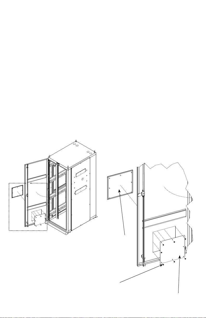
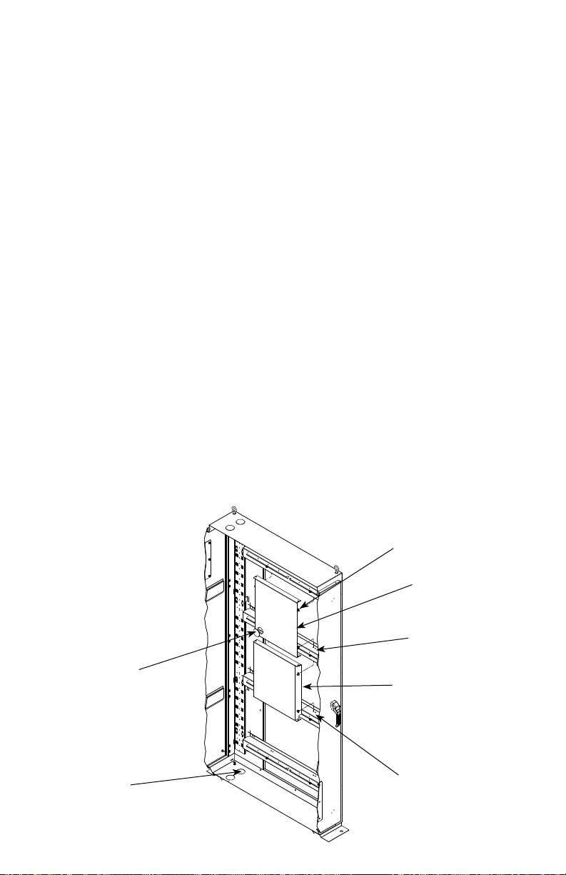
BAFFLE KIT
Each side panel comes with a bae kit that will be pre-installed at the
factory. There are two baes. One will direct conditioned air to the front
of the enclosure, the other will allow return air back to the A/C unit.
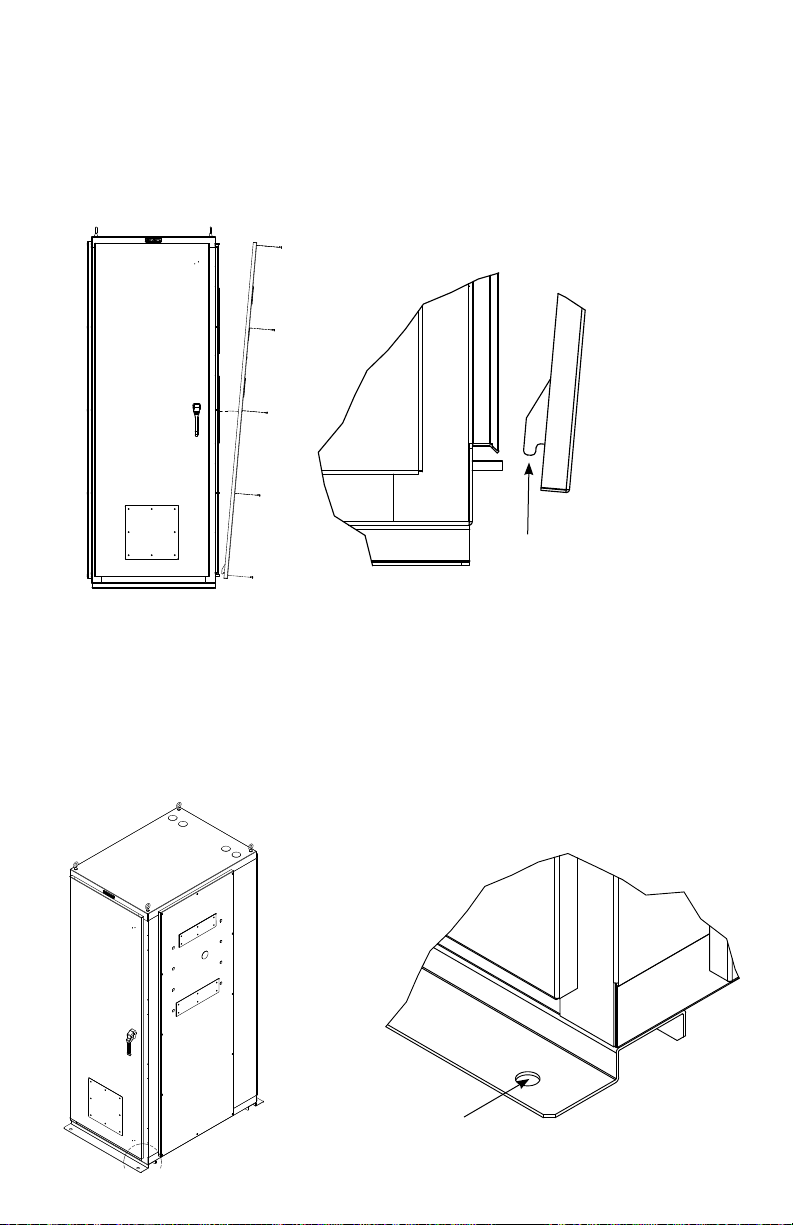
Button plug,
ush type
Ø 2"
Ø 2 3/8"
Electrical knockouts
x4 on bottom
x4 on top BOTTOM FRONT
Tuok panel
fastener
Top Bae for
30"W NEMA
Use rst hole
on horizontal for
placement
Note direction
of top and
bottom baes.
Crucial to proper
function of A/C
Use rst hole
on horizontal for
placement
10

3.719" x 13.750" Gland
back-up plate x 2
4.219" x 14.250" Gland plate
with 1/4 -20 x 3/4"L Pem Stud x
6 and 1/16" x 3/8"
4.5" x 16.5" Gland
plate with 1/4 -20 x
3/4"L Pem Stud x 6
and 1/16" x 3/8"
Button plug,
ush type
Ø 2" x 1
Button plug,
ush type
Ø 3/8" x 8
4.5" x 17.75" Gland
plate backup
1/4 -20 Elastic stop
nut x 12
SIDE PANEL “A”
The A/C unit cannot be pre-installed at the factory, it must be installed
on-site. The side panels have been designed so that no drilling or
cutting is required. Remove the gland plates and button plugs and the
side panel is ready to accept the A/C unit.
11

3.719" x 13.750"
Gland plate backup
4.219" x 14.250" Gland plate
with 1/4 -20 x 3/4"L Pem Stud
x 6 and 1/16" x 3/8"
4.5" x 17.75" Gland
plate with 1/4 -20 x
3/4"L pem Stud x 6
and 1/16" x 3/8"
Button plug,
ush type
Ø 1 1/4" x 2
Button plug,
ush type
Ø 3/8" x 2
Button plug,
ush type
Ø 1 1/4"
4.5" x 17.75"
Gland back-up plate
1/4 -20 Elastic
stop nut x 12
At this time, please nd the specic air conditioner instructions
and follow them carefully when mounting the A/C unit.
Important: To prevent excessive condensation, it is recommended
that you turn o the A/C unit when working on equipment within
the enclosure while door(s) are open.
SIDE PANEL “B”
12

PROTECTIVE GROUNDING
Protective grounding studs can be found in the top and bottom left
rear corners. Grounding jumper wires and copper bus bars for proper
grounding must be ordered separately.
DETAIL K
K
L
1
1
2
2
3
3
4
4
5
5
6
6
7
7
8
8
A A
B B
C C
D D
1/4-20 Double
Grounding Studs
PROTECTIVE GROUNDING
Protective grounding studs are provided
along with grounding jumper wires that
electrically bond the enclosure doors to
the enclosure frame.
M6 Ground
Stud
1/4-20 Double
Grounding Stud
13
WARNING: To avoid injury to persons or loss of life, ground each
enclosure individually to the dedicated branch circuit ground.
Connecting Main Protective Grounding Stud to the Dedicated
Branch Circuit Ground
Connect the dedicated branch circuit ground connector to the main
protective grounding stud located inside at the bottom rear of the
enclosure frame using a listed ring or closed-loop terminal.
Connecting Main Protective Grounding Stud to the Protective
Bonding Conductors
Connect the rear doors to the main protective grounding studs located
inside at the bottom and top rear of the enclosure chassis using a listed
ring or closed-loop terminal. Connect the front door to the grounding
stud located inside at the bottom front of the enclosure frame using a
listed ring or closed-loop terminal.
Parts Not Bonded to Protective Earthing Terminal
The following parts are not eectively bonded to the protective earthing
terminal: rails and front to back rail horizontals. If these parts need to
be bonded to the protective earthing terminal, do so in accordance with
Article 250 of the National Electric Code.

NOTES:
14

15
NOTES:

FORM: #MS - 5.02-26, REV #3
Thank you
for your
business!
ETSI Associate Member
This manual suits for next models
7
Table of contents
Other Great Lakes Enclosure manuals
Popular Enclosure manuals by other brands

Areca
Areca ARC-8042-12 Quick installation guide

Extron electronics
Extron electronics Cable Cubby 300C user guide

AMX
AMX AXB-TM5 Dimensional drawing

StorCase Technology
StorCase Technology Data Express Ultra320 DE100 user guide

HP
HP BladeSystem bc2800 - Blade PC reference guide

StarTech.com
StarTech.com 8STUNI251BMU33 instruction manual