GI-2
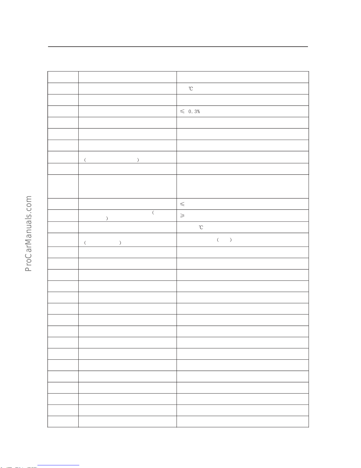
Key technical parameters for Model GW491QE petrol engine
S.N. Item Specification and parameters
1 Model Model GW491QE
2 Pattern Four-cylinder, inline, water-cooled, overhead valve,4-stroke
petrol engine
3 Fuel supply pattern Electronic controlled jet injection by group at multiple points
4 Measurement method for air intake
amount Velocity &density type
5 Pattern of combustion chamber Wedge typed
6 Diameter of cylinder bore 91mm
7 Piston stroke 86mm
8 Displacement 2.237L
9 Compression ratio 8.8:1(European class-II)9.1:1European class-III
10 Rated power 78kw/4600 r/min(European class-II)
78kw/4600 r/min(European class-III)
11 Max. torque 190·m/2400~2800 r/min
12 Min. fuel consumption rate ≤265g/kw·h(European class-II)≤250g/kw·h(European
class-III)
13 Fuel specRONNot lower than 93#GB17930-1999
14 Stable idle-speed 750±50r/min
15 Idle-speed control pattern Electronically closed-loop control
16 Piston average velocity 13.18m/s
17 Average valid pressure 874kpa
18 Compression pressure of cylinder
when at 250r/min1128kpa(European class-II); 1350kpaEuropean class-III
19 Ignition sequence 1-3-4-2
20 Ignition control pattern Without ignition distributor, and direct ignition under an
electronic control
21 Spark plug clearance 1.0~1.2mm
22 Model of spark plug F6RTC
23 Valve clearance 0mmhydraulic tappet
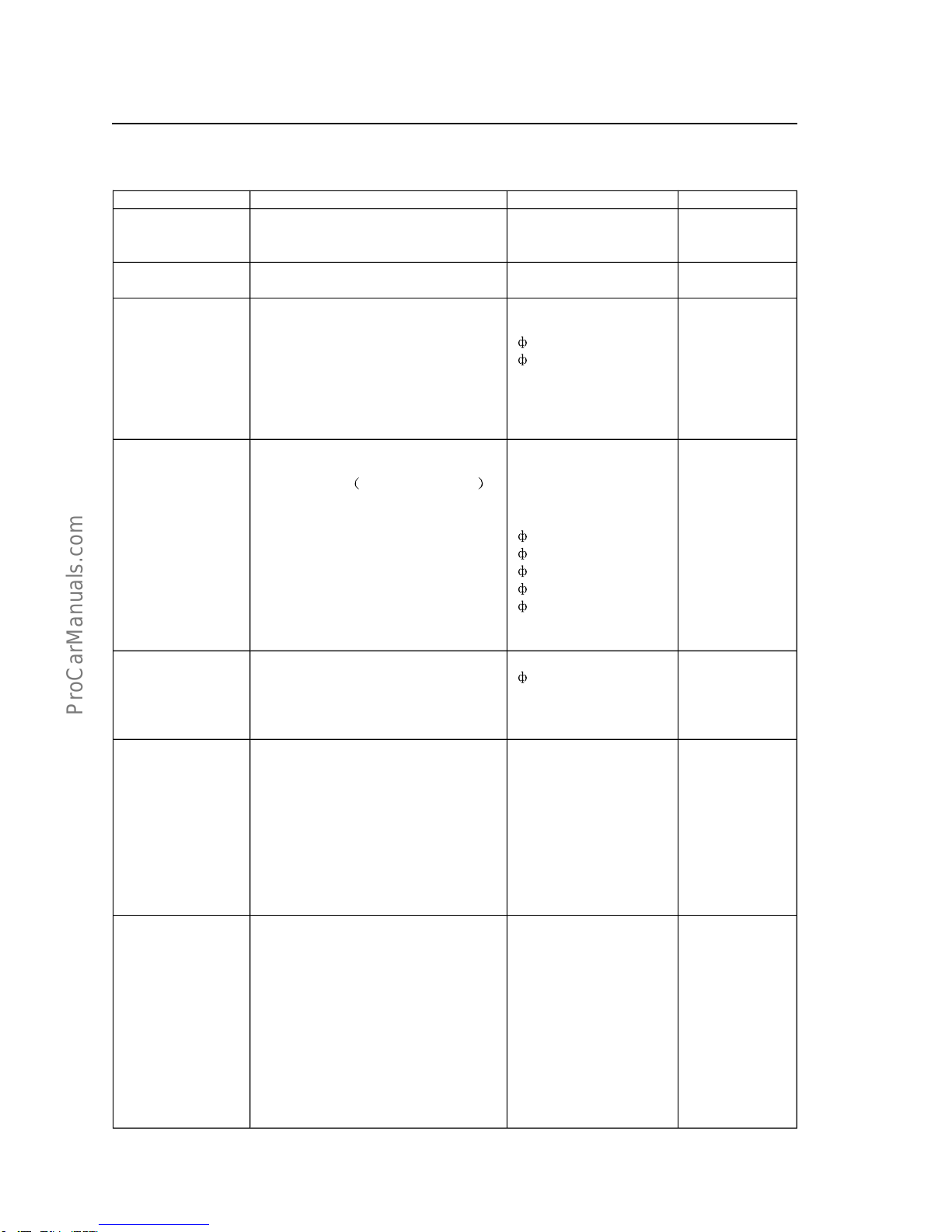
24
Valve timing:
Inlet-valve open lead angle;
Inlet-valve close lag angle;
Exhaust-valve open lead angle;
Exhaust-valve close lag angle;
12°before the top dead center,
48°before the bottom dead center;
54°before the bottom dead center;
10°before the top dead center;
25 Pattern of lubrication A combined pattern of pressure and splash.
26 Oil spec SG grade machine oil API10W-40GB11121-1995for petrol
engine
27
Main passage oil pressure
When at idle-speed 750±50r/min
or 3000r/min
49 kpa
(245-490) kpa
28 Oil capacity 4.2L
29 Oil temperature (85~90)℃
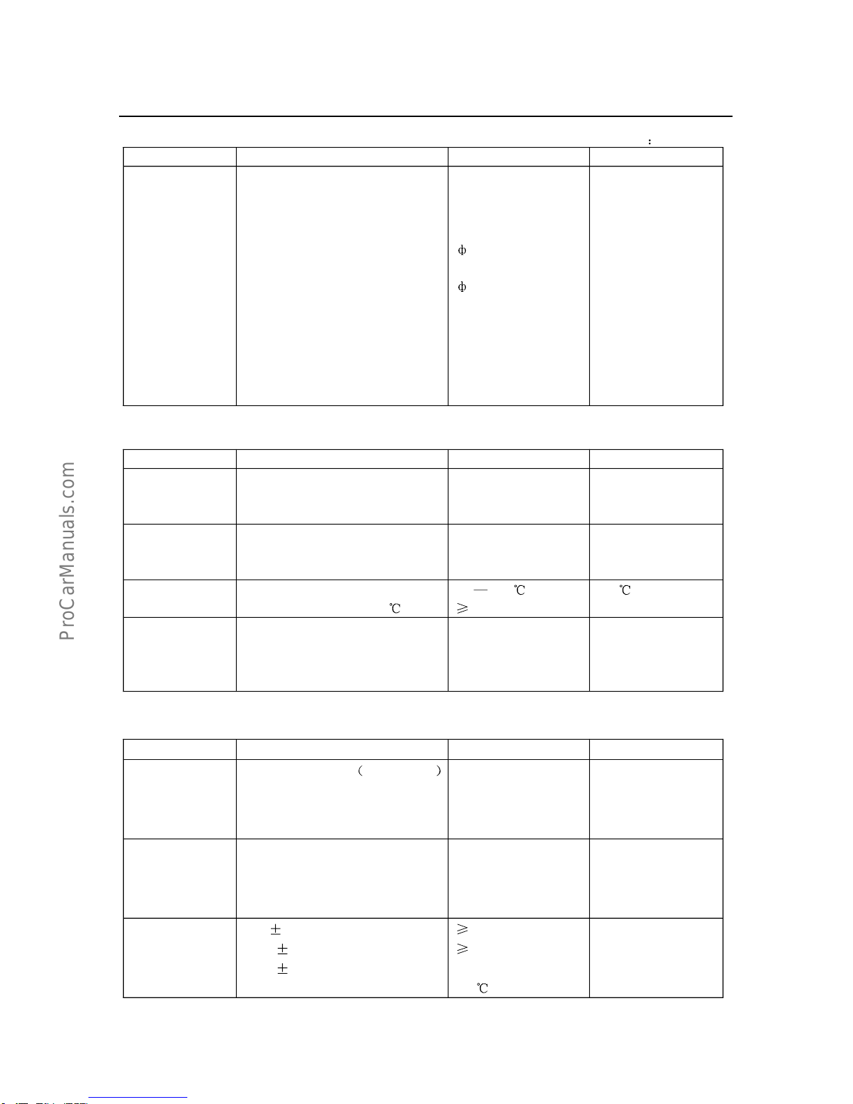
Engine service /maintenance data-Key technical parameters for Model GW491QE petrol engine
ProCarManuals.com