2Technical Information
Service Manual
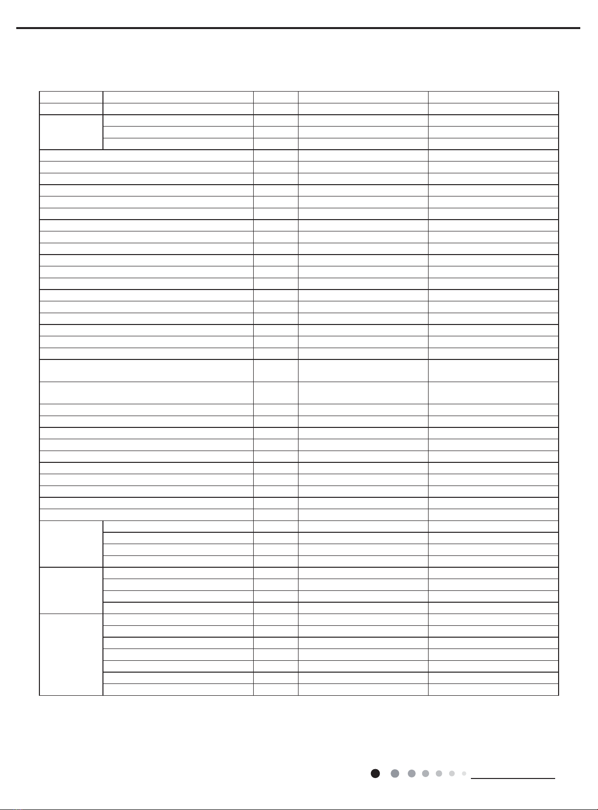
2.Specications
The above data is subject to change without notice; please refer to the nameplate of the unit.
Model GDN20AQ-E4EBA1A GDN24AQ-E4EBA1A
Product Code CK051021100 CK051021200
Power Supply
Rated Voltage V~ 220-240 220-240
Rated Frequency Hz 50 50
Phases 1 1
Rated Dehumidication Capacity L/h 0.48 0.52
Power Input W 260 280
Current Input A 1.3 1.3
Set Humidity Range % 35~80 35~80
Air Flow Volume(H/M/L) m3/h 185/165/145 185/165/145
Fan Motor Speed(H/M/L) r/min 1150/1050/980 1150/1050/980
Fan Motor Power Output W 8 8
Fan Motor RLA A 0.14 0.14
Fan Motor Capacitor μF 1.5 1.5
Fan Type Centrifugal Centrifugal
Fan Diameter Length(DXL) mm Φ180X62.5 Φ180X62.5
Throttling Method Capillary Capillary
Fuse Current A 3.15 3.15
Sound Pressure Level(H/M/L) dB (A) 48/46/44 48/46/44
Sound Power Level(H/M/L) dB (A) 58/56/54 58/56/54
Climate Type T1 T1
Isolation I I
Moisture Protection IPX0 IPX0
Permissible Excessive Operating Pressure for the
Discharge Side MPa 1.7 1.7
Permissible Excessive Operating Pressure for the
Suction Side MPa 0.6 0.6
Dimension (WXHXD) mm 351X492X260 351X492X260
Dimension of Carton Box(LXWXH) mm 404X326X515 404X326X515
Dimension of Package(LXWXH) mm 407X329X530 407X329X530
Application Area m228 34
Net Weight kg 15 15
Gross Weight kg 17 17
Refrigerant R134a R134a
Refrigerant Charge kg 0.13 0.2
Bucket Capacity L 3.6/4.2 3.6/4.2
Control Type Electronic Electronic
Evaporator
Evaporator Form Aluminum Fin-copper Tube Aluminum Fin-copper Tube
Evaporator Pipe Diameter mm Φ7 Φ7
Evaporator Row-n Gap mm 2-1.4 2-1.4
Evaporator Coil Length (LXDXW) mm 245X25.4X190.5 245X25.4X190.5
Condenser
Condenser Form Aluminum Fin-copper Tube Aluminum Fin-copper Tube
Condenser Pipe Diameter mm Φ5 Φ5
Condenser Rows-n Gap mm 2-1.4 3-1.4
Condenser Coil Length (LXDXW) mm 245X22.8X190.5 245X34.2X190.5
Compressor
Compressor Manufacturer RECHI PRECISION CO.,LTD. RECHI PRECISION CO.,LTD.
Compressor Model 39E0G3HR&F^YA 39E073HR&F^YA
Compressor Type Rotary Rotary
Compressor Power Input W 265 300
Compressor Overload Protector UP3-016 UP3-017
Compressor LRA. A 5.5 5.5
Compressor RLA A 1.2 1.4