manuals.online logo
Brands
  1. Home
  2. •
  3. Brands
  4. •
  5. Gree
  6. •
  7. Air Conditioner
  8. •
  9. Gree GMV MTAC VRF Series User manual

Gree GMV MTAC VRF Series User manual

This manual suits for next models

2

Other Gree Air Conditioner manuals

Gree CHANGE & COSY Series User manual

Gree

Gree CHANGE & COSY Series User manual

Gree GJC15BY-A6NRNC5A User manual

Gree

Gree GJC15BY-A6NRNC5A User manual

Gree GAE08AD-A3RNB2A User manual

Gree

Gree GAE08AD-A3RNB2A User manual

Gree GJC10BR-A3NRND2A User manual

Gree

Gree GJC10BR-A3NRND2A User manual

Gree GWC09KF-K3DNA5A User manual

Gree

Gree GWC09KF-K3DNA5A User manual

Gree Mini-Floor Console A Series User manual

Gree

Gree Mini-Floor Console A Series User manual

Gree TS15-12PACHPEC-A User manual

Gree

Gree TS15-12PACHPEC-A User manual

Gree GMV series User manual

Gree

Gree GMV series User manual

Gree UMatch UMAT18HP230V1AC User manual

Gree

Gree UMatch UMAT18HP230V1AC User manual

Gree GWH09AGA-K6DNA1A User manual

Gree

Gree GWH09AGA-K6DNA1A User manual

Gree GMVVQ224WM/C-X User manual

Gree

Gree GMVVQ224WM/C-X User manual

Gree DC Inverter Multi VRF User manual

Gree

Gree DC Inverter Multi VRF User manual

Gree GWH09RB-K3DNA2C User manual

Gree

Gree GWH09RB-K3DNA2C User manual

Gree Livo+ LIVS09HP230V1B User manual

Gree

Gree Livo+ LIVS09HP230V1B User manual

Gree Livo+ LIVS09HP115V1B User manual

Gree

Gree Livo+ LIVS09HP115V1B User manual

Gree GPC07AM-K5NNA2B User manual

Gree

Gree GPC07AM-K5NNA2B User manual

Gree GWH09QB-K3DNA6G User manual

Gree

Gree GWH09QB-K3DNA6G User manual

Gree GPC05AK-A3NNA2B User manual

Gree

Gree GPC05AK-A3NNA2B User manual

Gree GWH09AOCXD-K6DNA1B User manual

Gree

Gree GWH09AOCXD-K6DNA1B User manual

Gree GWH09KF-A3DNB1A User manual

Gree

Gree GWH09KF-A3DNB1A User manual

Gree EXTREME Series User manual

Gree

Gree EXTREME Series User manual

Gree KY-26 User manual

Gree

Gree KY-26 User manual

Gree GUHD18ND3FO User manual

Gree

Gree GUHD18ND3FO User manual

Gree GMV-H224WL/A-X User manual

Gree

Gree GMV-H224WL/A-X User manual

Popular Air Conditioner manuals by other brands

Fujitsu ASYG 09 LLCA installation manual

Fujitsu

Fujitsu ASYG 09 LLCA installation manual

York HVHC 07-12DS Installation & owner's manual

York

York HVHC 07-12DS Installation & owner's manual

Carrier Fan Coil 42B Installation, operation and maintenance manual

Carrier

Carrier Fan Coil 42B Installation, operation and maintenance manual

intensity IDUFCI60KC-3 installation manual

intensity

intensity IDUFCI60KC-3 installation manual

Frigidaire FAC064K7A2 Factory parts catalog

Frigidaire

Frigidaire FAC064K7A2 Factory parts catalog

Sanyo KS2432 instruction manual

Sanyo

Sanyo KS2432 instruction manual

LG MultiV Series installation manual

LG

LG MultiV Series installation manual

CLIMAVENETA a-CHD U-2T 606+2209 OPERATING AND INSTALLATION Manual

CLIMAVENETA

CLIMAVENETA a-CHD U-2T 606+2209 OPERATING AND INSTALLATION Manual

Midea EWK06CW5 user manual

Midea

Midea EWK06CW5 user manual

Pioneer FAB Series installation manual

Pioneer

Pioneer FAB Series installation manual

SPT WA-1511S user manual

SPT

SPT WA-1511S user manual

Mitsubishi Electric Mr.Slim MSZ-A24NA operating instructions

Mitsubishi Electric

Mitsubishi Electric Mr.Slim MSZ-A24NA operating instructions

Mitsubishi Electric PUHZ-RP50VHA4 Service manual

Mitsubishi Electric

Mitsubishi Electric PUHZ-RP50VHA4 Service manual

Panasonic CS-S18HKQ Service manual

Panasonic

Panasonic CS-S18HKQ Service manual

Panasonic CS-E15NKE3 operating instructions

Panasonic

Panasonic CS-E15NKE3 operating instructions

Friedrich ZoneAire Compact P08SA owner's manual

Friedrich

Friedrich ZoneAire Compact P08SA owner's manual

Daikin R32 Split Series installation manual

Daikin

Daikin R32 Split Series installation manual

Daikin FFQ09Q2VJU Operation manual

Daikin

Daikin FFQ09Q2VJU Operation manual

manuals.online logo
manuals.online logoBrands
  • About & Mission
  • Contact us
  • Privacy Policy
  • Terms and Conditions

Copyright 2025 Manuals.Online. All Rights Reserved.

GMV MTAC VRF for North America
(GC201908-I)
Capacity: 12kBtu/h
Rated Frequency: 60 Hz
CONTENTS
PRODUCT.................................................................................................................. 2
1 Product List............................................................................................................ 2
2 Product Features ................................................................................................... 2
2.1 General Introduction..................................................................................................... 2
3 Specifications ........................................................................................................ 3
3.1 Outdoor Unit................................................................................................................. 3
3.2 Operation Range.......................................................................................................... 4
4 Product Capacity Correction ................................................................................ 4
4.1 Instruction of Product Capacity Correction ................................................................... 4
4.2 Capacity Code ............................................................................................................. 4
4.3 Capacity Correction Formula........................................................................................ 4
5 Principal of Operation ........................................................................................... 6
CONTROL.................................................................................................................. 8
1 Units’ Control ......................................................................................................... 8
1.1 Schematic Diagram of Units’ Control............................................................................ 8
1.2 Operation Flow Chart ................................................................................................... 9
1.3 Unit Control Functions.................................................................................................10
2 Wired Controller ...................................................................................................11
2.1 Control Panel ..............................................................................................................11
2.2 Installation and Removal .............................................................................................14
3 Remote Controller ............................................................................................... 17
4 Monitoring Software ............................................................................................ 19
4.1 Function Introduction...................................................................................................19
4.2 Connection of Computer and Units .............................................................................19
4.3 Parts Introduction ........................................................................................................20
4.4 Software Introduction ..................................................................................................22
INSTALLATION........................................................................................................ 62
1 Engineering Installation Preparation and Notice .............................................. 62
1.1 Installation Notice........................................................................................................62
1.2 Installation Key Points and Importance........................................................................62
2 Installation Materials Selection .......................................................................... 63
2.1 Refrigerant Piping .......................................................................................................64
2.2 Condensate Water Pipe ..............................................................................................64
2.3 Insulation Material .......................................................................................................64
2.4 Communication Cable and Control Cable ...................................................................65
2.5 Power Cable ...............................................................................................................65
2.6 Hanger Rod and Support ............................................................................................65
3 Installation of Outdoor Unit ................................................................................ 65
3.1 Check before Installation.............................................................................................65
3.2 Selection of Installation Site ........................................................................................65
3.3 Carrying and Installing Outdoor Unit............................................................................66
3.4 Installation Notices ......................................................................................................66
3.5 Fixing and Damping of Unit .........................................................................................66
3.6 Outline Dimension and Position of Installation Hole ....................................................67
3.7 Installation Space Requirement...................................................................................67
4 Installation of Electronic Expansion Valve Assy (unit with external EXV)...... 68
5 Installation of Refrigerant Pipeline..................................................................... 68
5.1 Allowable Length and Height Difference of Connection Pipe .......................................68
5.2 Dimension of Pipe (Main Pipe) from ODU to the 1st Indoor Branch .............................69
5.3 Selection of Indoor Branches ......................................................................................69
5.4 Dimension of Pipe between Indoor Branches..............................................................70
5.5 Dimension of Pipe between Indoor Branch and IDU....................................................70
6 Installation of Connection Pipe .......................................................................... 71
6.1 Flaring Process ...........................................................................................................71
6.2 Vacuum Pumping, Refrigerant Adding.........................................................................75
7 Electric Wiring ..................................................................................................... 76
7.1 Wiring Diagram ...........................................................................................................77
7.2 Power Cable Wire Gauge and Circuit Breaker Selection.............................................78
8 Debugging of Unit ............................................................................................... 78
8.1 Preparation for Debugging ..........................................................................................78
8.2 Debugging of Unit .......................................................................................................79
8.3 Parameters Reference Value for the Normal Operation of Unit .......................................82
MAINTENANCE ....................................................................................................... 85
1 Malfunction List ................................................................................................... 85
1.1 Malfunction List for the Wired Controller......................................................................85
1.2 Status Display Table for Indicators on Main Board of Outdoor Unit..............................85
2 Troubleshooting .................................................................................................. 88
3 Power Distribution of Unit .................................................................................. 98
3.1 Power Distribution of Unit............................................................................................98
3.2 Main Electric Parts ......................................................................................................98
3.3 Circuit Diagram ...........................................................................................................99
4 Removal of Parts ................................................................................................. 99
4.1 Key Parts ....................................................................................................................99
4.2 Removal of Key Parts ...............................................................................................100
5 Common Maintenance ...................................................................................... 108
5.1 Vacuum Drying for the System ..................................................................................108
5.2 Fill and Charge Refrigerant .......................................................................................109
5.3 Airtightness Test........................................................................................................109
6 Exploded View of Unit and Parts’ List...............................................................111
Gree GMV MTAC VRF for North America
1
PRODUCT
Gree GMV MTAC VRF for North America
2
PRODUCT
1 Product List
Model Product
Code
Cooling
Capacity
Heating
Capacity
Power Supply
Refrigerant
Appearance
kW(Btu/h)
kW(Btu/h)
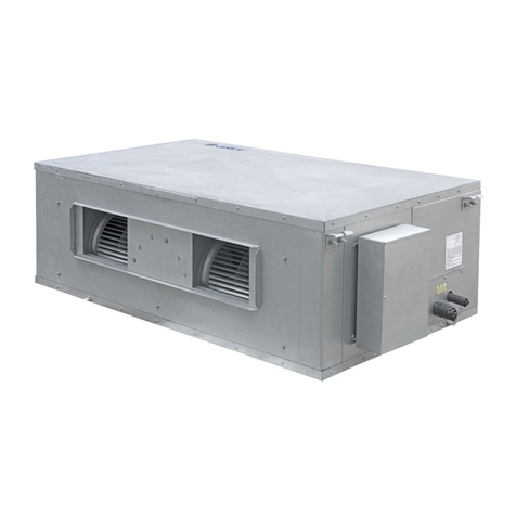
GMV-12WP/A-T(U)
CN850W0930 3.52
(12000)
3.52
(12000)
208V/230V~
60Hz R410A
2 Product Features
2.1 General Introduction
GMV MTAC is a kind of concealed VRF unit, which adopts front side air discharge and air
return. It’s mainly developed for North American market, which is applicable for apartments, offices,
hotels and other areas. The unit adopts deep subcooling technology for ensuring the quiet cooling
operation. Moreover, the unique drainage control technology has solved the problem of water
drainage of outdoor unit under low-temperature environment. Include GMV-12WP/A-T(U).
2.1.1 Features
(1) Super high energy efficiency.
The system adopts all DC motor, which greatly improves efficiency. The energy efficiency for
Gree all DC unit is increased greatly. SEER of GMV-12WP/A-T(U) is up to 15.5; HSPF of
GMV-12WP/A-T(U) is up to 9.5.
(2) New generation CAN bus communication.
Due to the latest communication method—CAN Bus Communication, system’s
anti-interference capability is stronger and the control on indoor units is more accurate, with higher
reliability. Specialized shield wire is no more needed and ordinary communication wire can be
applied in the construction, which has increased the installation flexibility.
(3) Long connection pipe.
GMV-12WP/A-T(U):
The maximum length of connection pipe is 30m(98-3/8ft) (in total) and the farthest connection
pipe between indoor and outdoor units can be 30(98-3/8ft) m’s long, which has extended the
installation condition and reduced the limit of installation distance.
(4) Wide operation range.
Units can operate reliably in a wide temperature range (cooling: -5~48°C(23~118.4°F),
heating: -20~27°C(-4~80.6°F)).
(5) Fine sound quality.
Through a series of optimized measures, system has reduced the throttle noise and oil return
noise of indoor units, gas bypass noise, etc. so that units are more comfortable regarding sound
quality.
Gree GMV MTAC VRF for North America
3
(6) Intelligent PID capacity regulation.
With the independently developed PID capacity regulation technology, units are able to
control the indoor ambient temperature more quickly and reduce the fluctuation of room
temperature.
(7) Complete protection.
Units are equipped with a series of protection to accurately identify errors and protect the units,
which has ensured reliable and safe operation.
3 Specifications
3.1 Outdoor Unit
Model
GMV-12WP/A-T(U)
Cooling capacity
kW
3.52
Btu/h
12000
Heating capacity
kW
3.52
Btu/h
12000
Circulating air volume
m
3
/h
850
CFM
500
Noise
dB(A)
Indoor46/Outdoor57
Refrigerant charge volume
Kg
0.8
oz
28.2
Power supply
208V/230V~60Hz
Rated power input
Cooling
kW
1.4
Heating
kW
1.1
Unit Dimensions (W×D×H)
mm
1069×500×406
inch
42-1/16×19-11/16×16
Dimensions (W×D×H)
mm
1164×601×470
inch
45-13/16×23-11/16×18-8/16
Compressor
SNB150FGAMC
Water-proof level
IPX4
Suitable climate
T1
Connection pipe
Gas
mm
Φ12.7
inch
Φ1/2
Liquid
mm
Φ6.35
inch
Φ1/4
Connection Method
Flare Connection
Net weight
Kg
55
oz
121
NOTICE!
①Units conform to design standard: ARI 210/240.
②Specifications may be changed due to product improvement. Please refer to nameplates
of the units.
③Noise data are collected from a semi-anechoic room. Decibels may be slightly higher in
actual operation due to environmental change.
④Refrigerant charge volume listed in the table is based on the condition where indoor and
Gree GMV MTAC VRF for North America
4
outdoor units are at a same level and with no connection pipe. Supplementary refrigerant
needs to be charged according to actual circumstance.
3.2 Operation Range
Cooling
Outdoor temperature: -5~48°C (23~118.4°F)
Heating
Outdoor temperature: -20~27°C(-4~80.6°F)
4 Product Capacity Correction
4.1 Instruction of Product Capacity Correction
Nominal cooling capacity and nominal heating capacity are tested under given conditions:
(1) Rated cooling or heating condition.
(2) No height difference between indoor unit and outdoor unit.
(3) Short connection pipe.
If the three conditions above have changed, the cooling and heating capacity will change
correspondingly and correction is needed.
4.2 Capacity Code
Instruction of capacity code.
GMV-12WP/A-T(U) are identical in components, systems and structure, etc.. While the
required capacity is set through the capacity DIP switch.
Sheet of DIP Switch (5-bit DIP switch)
Model
Bit 1
Bit 2
Bit 3
Bit 4
Bit 5
GMV-12WP/A-T(U)
0
1
1
1
0
4.3 Capacity Correction Formula
4.3.1 Rated Capacity of Outdoor Unit
Model
GMV-12WP/A-T(U)
Rated cooling capacity
kW
3.52
Btu/h
12000
Rated heating capacity
kW
3.52
Btu/h
12000
Gree GMV MTAC VRF for North America
5
4.3.2 Correction Factor of Indoor and Outdoor Temperature
(1) Correction factor of cooling capacity.
(2) Correction factor of heating capacity.
4.3.3 Correction Factor of Pipe Length and Height Difference
Symbol description:
Hp: Height difference in case indoor unit is below outdoor unit(m/feet).
Hm: Height difference in case indoor unit is above outdoor unit (m/feet).
L: Length of one-way equivalent pipe.
Gree GMV MTAC VRF for North America
6
Below table shows the capacity variance ratio for 100% full load in standard working condition
(thermostat setting is 16°C(61°F ) for cooling and 30°C(86°F ) for heating).
50
40
30
20
Hp(m)
L(m) L(m)
Hm(m)
10
10
1.0
1.0
0.99
0.97
0.95
0.97
0.95
0.93
0.89
0.91
0.87
20 30 40 50 60 70 80 90 100 110 120 130140150 10 20 30 40 50 60 70 80 90 100 110 120 130140150
0
10
20
30
40
50
40
30
20
Hp(m)
Hm(m)
10
0
10
20
30
40
Change rate of cooling capacity Change rate of heating capacity
Variance ratio of heating capacity
NOTICE!
m
0
10
20
30
40
50
60
70
80
90
100
110
120
130
140
150
ft
0
33
66
98
131
164
197
230
262
295
328
361
394
427
459
492
5 Principal of Operation
Components in flowcharts are presented according to the following table:
Name Compressor 4-way valve Cut-off
valve
One-way valve Capillary tube
Symbol
Name Gas-liquid
separator
Pressure
switch
Pressure
sensor
Axial-flow finned heat
exchanger
Electronic expansion valve
Symbol
In cooling, the low-temperature and low-pressure refrigerant gas from each indoor heat
exchanger will be merged and inhaled by the compressor and then become high-temperature and
high-pressure gas, which will later be discharged into outdoor heat exchangers. By exchanging
heat with outdoor air, refrigerant will turn to liquid and flow to each indoor unit via Y-type branch or
manifold. Pressure and temperature of the refrigerant will then be lowered by throttle elements
before it flows into indoor heat exchangers. After exchanging heat with indoor air, refrigerant wil
become low-temperature and low-pressure gas again and repeat the circulation so as to realize
the cooling effect. In heating, 4-way valve will be energized to make refrigerant circulate in a
reverse direction of cooling. Refrigerant will release heat in indoor heat exchangers (electric
heating elements will also work under certain circumstance and release heat) and absorb heat in
outdoor heat exchangers circularly so as to realize the heating effect.