Contents
ⅠWired Remote Controller XK19
1 Symbols on LCD
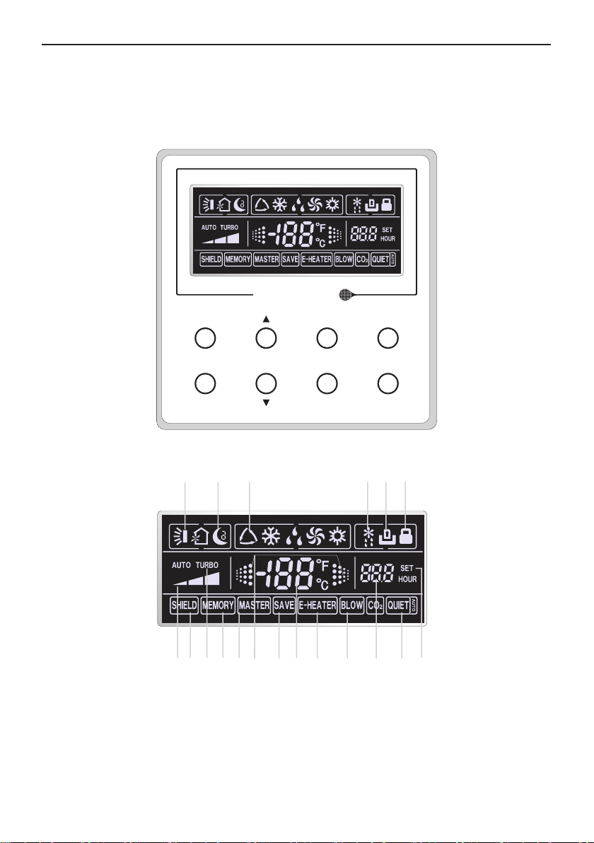
1.1 Outside View of the Wired Remote Controller
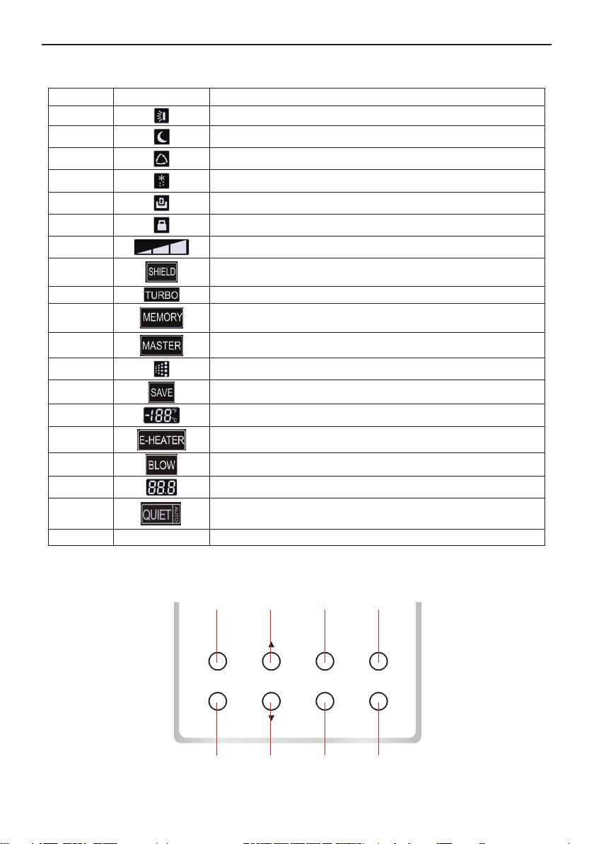
1.2 LCD of the Wired Remote Controller
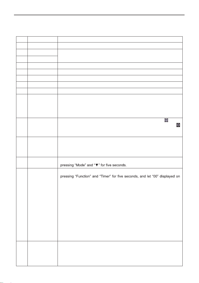
2.1 Buttons on the Wired Remote Controller
2 Buttons
2.2 Function of the Buttons
3 Operation Instructions
3.1 On/Off
3.2 Mode Setting
3.3 Temperature Setting
3.4 Fan Setting
3.5 Timer Setting
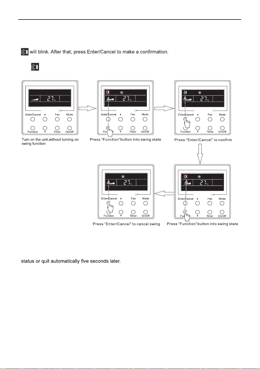
3.6 Swing Setting
3.7 Fresh Air Valve Function Setting
3.8 Sleep Setting
3.9 Turbo Setting
3.10 Energy Saving Function Setting
3.11 E-heater Setting
3.12 Blow Setting
3.13 Quiet Function Setting
3.14 Other Functions
4 Installation and Dismantlement
4.1 Connection of the Signal Line of the Wired Remote Controller
4.2 Installation of the Wired Remote Controller
4.3 Dismantlement of the Wired Remote Controller
5 Errors Display
ⅡWireless Remote Controller YT1F
1 Function of Press Buttons
2 Guide for General Operation
3 Guide for Optional Operation
................................................................................................
.................................................................................
............................................................................
...........................................................................
......................................................................................................
......................................................................................................
......................................................................................................
......................................................................................................
......................................................................................................
.......................................................................................................
.........................................................................................................
.................................................................................................................
................................................................................................
...........................................................................................
.................................................................................
............................................................................................
..............................................................
................................................................
........................................................................................................
......................................................................................
........................
......................................................
...............................................
........................................................................
......................................................................................
............................................................
..................................................................
....................................................
.......................................................................
....................................................................
..........................................................................................
15
17
17
17
20
23
20
23
25
26
14
13
12
11
10
9
8
7
5
5
4
4
4
4
3
2
2
1
1
1
1