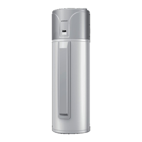
Gree GRS-1.5/TD150ANbA-K User manual

Owner's Manual
Original Instructions
Air Source Heat Pump Water Heater
Models:
GRS-1.5/TD150ANbA-K
GRS-1.5/TD200ANbA-K

To Users
Thank you for selecting Gree’s product. Please read this instruction manual
carefully before installing and using the product, so as to master and correctly use
the product. In order to guide you to correctly install and use our product and
achieve expected operating effect, we hereby instruct as below:
(1) This appliance is not intended for use by persons (including children) with
reduced physical, sensory or mental capabilities, or lack of experience
and knowledge, unless they have been given supervision or instruction
concerning use of the appliance by a person responsibility for their safety.
Children should be supervised to ensure that they do not play with the
appliance.
(2) In order to ensure reliability of product, the product may consume some
power under stand-by status for maintaining normal communication of
system and preheating refrigerant and lubricant. If the product is not to be
used for long, cut off the power supply; please energize and preheat the
unit in advance before reusing it.
(3) Please properly select the model according to actual the using
environment, otherwise it may impact the using convenience.
(4) This product has gone through strict inspection and operational test
before leaving the factory. In order to avoid damage due to improper
disassembly and inspection, which may impact the normal operation of
unit, please do not disassemble the unit by yourself. You can contact with
the special maintenance center of our company if necessary.
(5) When the product is faulted and cannot be operated, please contact with
our maintenance center as soon as possible by providing the following
information.
1)Contents of nameplate of product (model, cooling/heating capacity,
product No., ex-factory date).
2)Malfunction status (Specify the situations before and after the error
occurs).
(6) All the illustrations and information in the instruction manual are only for
reference. In order to make the product better, we will continuously
conduct improvement and innovation. We have the right to make

necessary revision to the product from time to time due to the reason of
sales or production, and reserve the right to revise the contents without
further notice.
(7) The final right to interpret for this instruction manual belongs to Gree
Electric Appliances Inc. of Zhuhai.
Exception Clauses
Manufacturer will bear no responsibilities when personal injury or property loss
is caused by the following reasons:
(1) Damage the product due to improper use or misuse of the product;
(2) Alter, change, maintain or use the product with other equipment without
abiding by the instruction manual of manufacturer;
(3) After verification, the defect of product is directly caused by corrosive gas;
(4) After verification, defects are due to improper operation during
transportation of product;
(5) Operate, repair, maintain the unit without abiding by instruction manual or
related regulations;
(6) After verification, the problem or dispute is caused by the quality
specification or performance of parts and components that produced by
other manufacturers;
(7) The damage is caused by natural calamities, bad using environment or
force majeure.

Contents
1 Safety Notices (Please be sure to abide) .................................................1
2 Technical Description................................................................................7
2.1 General Description ........................................................................... 7
2.2 Main parts .......................................................................................... 8
2.3 Operating Principle ............................................................................ 9
2.4 Technical Specifications ...................................................................10
3 Installation Notice.................................................................................... 11
3.1 Important Prompt ............................................................................. 11
3.2 Basic Requirement on Installaion Location......................................12
4 Water Heater Installation ........................................................................12
4.1 Selection for Water Heater Installation Location..............................12
4.2 Installation Space Requirement and Installation Diagram ...............13
4.2.1 Main Size................................................................................... 13
4.2.2 Installation requirement .............................................................13
4.3 Water Pipe Connection ....................................................................16
4.4 Unit Installation Diagram ..................................................................20
5 Electrical Wiring ......................................................................................21
5.1 Electrical Wire Layout ......................................................................21
5.2 Electrical Wiring and Connection .....................................................23
6 Debugging for the complete unit.............................................................23
7 Method to Supplement or Discharge Refrigerant ...................................25
7.1 Supplement Refrigerant ...................................................................25
7.2 Discharge Refrigerant ......................................................................26
8 Unit Performance ....................................................................................26
8.1 Water Heating Capacity ...................................................................26
8.2 Operation Performance....................................................................27
9 Operation Notices in Winter....................................................................27
10 Maintenance .........................................................................................28
10.1 Water Input and Drainage of Water Tank.......................................28
10.2 Periodic Cleaning for Water Tank...................................................29
10.3 Maintenance of Safety Valve .........................................................29
10.4 Maintenance of the Unit .................................................................30
10.5 Periodic Check for Electricity Leakage Protection Switch .............30
10.6 Safety Notices While Moving the Unit............................................30
11 Precautions for Safety Usage ...............................................................31
12 Malfunction Analysis .............................................................................31

Air Source Heat Pump Water Heater
1
1 Safety Notices (Please be sure to abide)
WARNING: If not abide strictly, it may cause severe damage to the unit or
the people.
NOTICE: If not abide strictly, it may cause slight or medium damage to the
unit or the people.
This sign indicates that the operation must be prohibited. Improper
operation may cause severe damage or death to people.
This sign indicates that the items must be observed. Improper operation
may cause damage to people or property.
WARNING!
This product can’t be installed at corrosive, inflammable or explosive
environment or the place with special requirements, such as kitchen. Otherwise, it
will affect the normal operation or shorten the service life of the unit, or even cause
fire hazard or serious injury. As for the special places above, please adopt special
product with anti-corrosive or anti-explosion function.
Air source water heater is a thermal storage water heater. The user shall open
the cold water valve first, then adjusting cold and hot water flow to proper water
temperature gradually to avoid scald injury. If not using the unit in winter in short
time, please ensure that it is energized for the whole 24h, if not unit using the unit
for a long period, discharge water in water tank and pipeline in case the system is
frosted. If you think the discharge operation is inconvenient, please directly contact
our local distributors or authorized service branch, we will appoint special staff to
provide inspection, debug, cleaning and maintenance services.
This manual is the usage and installation manual for unitary air source water
heater. Usage method for displayer shall refer to the attached Displayer Manual.

Air Source Heat Pump Water Heater
2
Water inlet of water tank must install safety valve as required;
Try to use tap water, avoid not using well water or river water;
To guarantee water quality, clean the water tank periodically as required;
Water tank shall be installed in places without rainwater. If not, take
rain-proof measures.
NO.
Safety Notices
Graphic symbol
1
★Once abnormality like burning smell occurs,
please cut off the power supply immediately and
then contact with service center.
If the abnormality still exists, the unit may be
damaged and electric shock or fire may result.
2 ★Don't operate water heater with wet hand.
Otherwise, it may cause electric shock.
3
★Before installation, please see if the voltage of
local place accords with that on nameplate of unit
and capacity of power supply, power cord or socket
is suitable for input power of this unit.
4
★Special circuit must be adopted for power supply
to prevent fire.
Do not use octopus multipurpose plug or mobile
terminal board for wire connection.
5
★Be sure to pull out the power plug and drain the
main unit and water tank when water heater is not in
use for a long time.
Otherwise, the accumulated dust may cause
overheating, fire or freeze of water tank or coaxial
heater exchanger in winter.
6
★Never damage the electric wire or use the one
which is not specified.
Otherwise, it may cause overheating or fire.

Air Source Heat Pump Water Heater
3
NO.
Safety Notices
Graphic symbol
7
★Before to clean, please cut off the power supply.
Otherwise, an electric shock hazard may be
caused.
8 ★The power supply must adopt special circuit with
leakage switch and enough capacity.
9
★This appliance is not intended for use by persons
(including children) with reduced physical, sensory
or mental capabilities, or lack of experience and
knowledge, unless they have been given
supervision or instruction concerning use of the
appliance by a person responsible for their safety.
Children should be supervised to ensure that they
do not play with the appliance.
10
★Earthing: the unit must be earthed reliably! The
earthing wire should connect with special device of
buildings.
If not, please ask the qualified personnel to
install. Furthermore, don't connect earth wire to gas
pipe, water pipe, drainage pipe or any other
improper places which professional does not
recognize.
11
★Do not put any foreign matter into the unit,
otherwise it would cause the unit being damaged or
result in danger. Never put your hands at the air
outlet of the unit.
12
★Do not repair the unit by yourself, in case of
electric shocks or fire hazards. Please contact the
GREE appointed service center.

Air Source Heat Pump Water Heater
4
NO.
Safety Notices
Graphic symbol
13 ★Do not step or place objects on the unit, as they
would be injured or damaged when falling off.
14
★Do not block the air inlet of the unit, otherwise it
would reduce the efficiency of the unit, stop it, or
even result in fire hazards.
15
★Keep the unit upright and do not tilt it during
transport, handling and installation, otherwise it
would be damaged.
16
★Keep the chemical spray, gas tank or others
similar at least 1m away from the unit, otherwise it
would lead to fire hazards or explosion.
17
★This series adopts electronic anode for corrosion
prevention, energize it to allow water tank to assist
anode weak current, thus protecting inner tank.
Therefore, do not cut off the power of the unit,
otherwise, electronic anode will not protect water
tank.
18
★If thermal water tank has no water or water is not
full, please do not energize the unit for startup,
otherwise, it might damage the unit or result in fire
hazard.

Air Source Heat Pump Water Heater
5
NO.
Safety Notices
Graphic symbol
19 ★It is highly recommended to place the unit where
good ventilation is available.
20
★Check the safety relief valve for blockage
periodically (about one month) by removing the
hand grip and operate it periodically (about one
year).
21 ★It is a normal phenomenon that the safety relief
valve drips.
22 ★The safety relief valve shall be got through to the
floor drain through a flexible tube.
23
★The safety relief valve shall be installed properly
with the direction arrow indicated the same direction
as the cold water flow.
24
★It is recommended to install horizontally the filter
downstream of the main cut-off valve of the user’s
water pipe. Please note that the direction arrow on
the filter shall indicate the direction the same as the
water flow. When it is required to remove impurity
inside the water circuit, open the end cover of this
filter.

Air Source Heat Pump Water Heater
6
NO.
Safety Notices
Graphic symbol
25
★When the filter is installed vertically, the direction
arrow can not be upward and the end cover shall be
placed slantwise downwards.
26
★This marking indicates that this product should
not be disposed with other household wastes
throughout the EU. To prevent possible harm to the
environment or human health from uncontrolled
waste disposal, recycle it possibly to promote the
sustainable reuse of material resources. To return
you used device, please use the return and
collection systems or contact the retailer where the
product was purchased. They can take this product
for environmental safe recycling.
27
★This unit contains fluorinated gas with
greenhouse effect covered by the Kyoto Protocol.
Maintenance and disposal must be carried out by
qualified persons only.
Refrigerant gas R134a, GWP=1430.
28
★The fuse model and rated value are in
accordance with the corresponding controller or the
silk screen attached on the protective tube.

Air Source Heat Pump Water Heater
7
2 Technical Description
2.1 General Description
(1) High Efficiency
Under the self-adjustable control of the electronic expansion valve, the air
source heat pump water heater heats water with heat energy in the air. Its rated
working condition efficiency ratio is 3.5 W/W.
(2) Safe and Environment Friendly
Separation of water and electricity gets rids of the potential risks of electric
shocks and there is no worry for carbon monoxide poisoning. Safety is guaranteed
for the user. During operation, it releases no pollutant and does no harm to the
environment.
(3) Durable
Adopt special compressor for water heater, high temperature and high pressure
resistible; thermal insulation water tank adopts enamel inner tank with advanced
technology, at the same time electronic anode is also equipped. Through the
self-adjustable control of the weak current in inner tank, it provides stable and
overall protection for the inner tank, which is corrosion resistant efficiently with
service life up to 10 years. No replacement is needed, which is zero consumption;
multiple protection for the whole unit to ensure durable use of the system.
(4) Easy installation
Without restrictions of the installation location, it is available to be located in the
kitchen, garage, storage room, basement etc., requiring no attendance and widely
applicable to residential houses and villas. No circulated waterway system,
installation and maintenance convenient.
(5) Simple operation
The water temperature set point can be freely adjusted by the user and the
user is allowed to time the water heater for when to start or stop it, which will help
the user avoid the peak hours of electricity consumption and reduce the electricity
cost.
(6) Intelligent defrosting
Antifreeze protection and automatic defrosting both are available for the heat
exchanger vulnerable to frosting and incomplete defrosting.

Air Source Heat Pump Water Heater
8
(7) All-weather operation
It is able to operate all year around whatever the weather is like.
(8) Corrosion prevention design of electronic anode
Model of this unit adopts advanced electronic anode corrosion prevention
design. Unlike traditional principle of sacrificing anode (active metal magnesium) for
corrosion prevention, it adopts insoluble Ti as auxiliary anode, and connects
auxiliary anode and inner tank to the weak direct current. After power is on, the
electron will flow to inner tank forcibly and form an electron oxidation on the surface,
thus avoiding metal oxidation in inner tank and protecting the effect.
Corrosion prevention of electron anode has the advantages of long service life,
no pollution and good self-adaptation.
2.2 Main parts
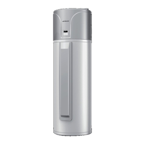
This air source water heater product and water system pipeline constitute the
whole structure, providing domestic hot water for the use.
Product outline diagram is as follows. Due to reasons like product upgrade,
practical product might be inconsistent with the diagram without further notice,
please subject to the actual objects.
Figure 2-1 Product outline diagram

Air Source Heat Pump Water Heater
9
2.3 Operating Principle
Figure 2-2 Air source water heater operating principle
The air source water heater is driving the compressor by some part of
electricity by using the heat pump principle. Through the thermal circuit, absorb the
heat from the low-grade energy (air) in the surrounding environment, transmit it to
the heat exchanger of water tank and then release it to the water inside the water
tank for heating water.
The heating principle for air source water heater and heat pump air conditioner
is the same. Heat pump air conditioner supplies the absorbed heat from natural
environment to indoor air, while air source will use that heat to heat domestic water.
Air source water heater is a kind of new, high-efficiency, energy-saving and
eco-friendly water heater.

Air Source Heat Pump Water Heater
10
2.4 Technical Specifications
Model
GRS-1.5/TD150ANbA-K
GRS-1.5/TD200ANbA-K
Rated Heating Capacity
(*)
W
1500
1500
Rated Input Power(*)
W
429
429
COP(*)
W/W
3.50
3.50
Capacity
L
150
190
Load Profile
-
L
L
COPDHW(**)
W/W
2.47
2.24
Energy Efficiency Class(**)
-
A
A
Water Heating Energy
Efficiency
(**)
- 104% 95%
Annual electricity
consumption
(average climate conditions)
kWh 985 1075
Maximum Input Power
W
650+1500W (Electric Heater)
Outlet Water Temperature
-
Default: 55°C, 35°C~70°C
Power Supply
-
220V-240V ~ 50Hz
Insulation Level
-
Ⅰ
Ⅰ
Protection of Ingression
-
ⅠPX4
ⅠPX4
Refrigerant
Name
R134a
R134a
Charge
kg
0.8
0.8
Outline
Dimensions
W×D×H mm 621×561×1760 621×561×2030
Package
Dimensions
W×D×H mm 731×717×1845 731×717×2110
Gross/Net Weight
kg
112.0/92.0
122.5/102.5
Sound Power Level
(***)
dB(A)
62
62
Operating Range
°C
0~45
0~45
NOTES:
①(*) Value obtained with the following conditions: Outdoor temperature:
20°CDB/15°C WB; Water tank temperature (start/end): 15°C /55°C.
②(**) Value obtained with an air temperature of 7°C and a water inlet at 10°C,
as per EN16147, (EU) No 814/2013.
③(***) Value obtained as per EN 12102-2008.
④Under Rapid function, electric heater helps to heating water.
⑤Please always see the nameplate for the exact data as this table is subject
to change.

Air Source Heat Pump Water Heater
11
3 Installation Notice
3.1 Important Prompt
(1) It shall be installed by the skilled personnel in accordance with the
national wiring rules and instructions covered in this manual.
(2) Please contact the GREE appointed service center prior to installation,
otherwise, faults due to installation by the non-appointed service center
would be handled difficultly. For any air source heat pump water heaters
which are not installed by our franchised entrusted party, if malfunctions
occur or resulting in other problems, Gree shall not be liable.
(3) To install and remove air source heat pump water heater, please contact
local Gree authorized maintenance center. If the user use self-prepared
materials to install our air source heat pump water heater, all losses
resulted in pipeline leakage, falling off and improper installation, which
might affect normal operation and usage of air source heat pump water
heater, Gree shall not be liable.
(4) The heat pump can operate when the ambient temperature is above 0°C,
the water heater can only be put indoors and must be installed at the
places where the ambient temperature is above 0°C. If the ambient air
temperature falls lower than 0°C, the condensate water drainage may be
freezing.
(5) The nozzle with the rated flow of 6~7L/min is preferred.
(6) If water supply is of high salinity or inferior quality, proper filtering or
depuration is necessary.
(7) The water quality for the air source water heater should comply with the
local sanitation standard for the domestic drinking water.

Air Source Heat Pump Water Heater
12
3.2 Basic Requirement on Installaion Location
The unit will go into faults when installed in the locations listed below. If
inevitable, please contact the GREE appointed service center for further service.
(1) Where there are intense heat sources, steam, inflammable or explosive
gas or volatile substances.
(2) Where there are high-frequency devices, like welding machines, medical
equipments, etc.
(3) Where the environmental PH is high, voltage fluctuation is high, located in
vehicle or ship.
(4) Where there is oil (mechanical oil) in air.
(5) Where there is sulphide gas.
(6) Other special environments.
4 Water Heater Installation
4.1 Selection for Water Heater Installation Location
(1) Suggest installing the unit indoors. But do not make the wind blowing to
the living room.
(2) The noise and air flow generated at the air outlet will not influence your
neighbors, animals and plants.
(3) Good ventilation is available.
(4) It is able to withstand the weight and vibration of the unit and it is available
for safe installation.
(5) It is dry but not subject to direct sunlight or strong wind.
(6) Don’t install it in places with electromagnetic interference.
(7) It agrees with the installation dimensions of the unit and is accessible for
inspection and maintenance.
(8) It is out of touch of the children.
(9) It will not affect the public passages and the city layout.
NOTES:
①As unit operation will generate cold air, certain noise will occur, do not install
it in places with frequent activity by the user. Any harmful effect due to
improper installation location, Gree shall not be liable.

Air Source Heat Pump Water Heater
13
2Due to installation location limit, if this model cannot meet installation
demand, please choose other water heaters of Gree models.
4.2 Installation Space Requirement and Installation Diagram
4.2.1 Main Size
A
B
D
CE
Condensate Outlet
Hot Water Outlet
Temperature Sensor 1
Impressed Current Anode
Temperature Sensor 2
Cold Water Inlet
Figure 4-1 Unit struture size chart
Model
Parameter
GRS-1.5/TD150ANbA-K
GRS-1.5/TD200ANbA-K
A(mm)
Φ540
Φ540
B(mm)
1760
2030
C(mm)
1206
1476
D(mm)
186
186
E(mm)
1032
1302
4.2.2 Installation requirement
(1) The unit shall be installed upright on the strong enough balcony or floor.
Do not point the air outlet of water heater at the upwind direction.
(2) The unit shall be installed in places with the temperature of above 0°C.
Hot water outlet shall not be too far from hot water use site. Arrange the

Air Source Heat Pump Water Heater
14
pipeline together, and conduct thermal insulation treatment to hot water
pipeline to decrease heat capacity loss. If the unit is installed in places
with the temperature of below 0°C, conduct thermal insulation treatment
to water inlet/outlet to prevent water pipe and safety valve getting frozen
under low temperature, thus resulting in malfunction of water tank.
(3) The distance between water heater and surrounding wall or other shelter
objects can’t be too close. The installation space should satisfy the
installation space requirement.
Figure 4-2 Installation space requirement
(4) When a weather shed is set up to protect the unit, be sure heat release
and heat absorption by the heat exchange will not be affected.
(5) The unit shall be located upright with its feet down to earth. The
installation location shall be strong. Water tank installation shall consider
bearing capacity of installation location.

Air Source Heat Pump Water Heater
15
Figure 4-3 Unit installation diagram
NOTICE!
The unit also shall be fixed to wall with clamping bands in case of tilt in some
unusual occasions.
(6) There should be cold and hot water sources and floor drain near the unit
so that it will be easy to add water for the water tank and drain it.
(7) Be sure the condensate pipe and the condensate outlet are reliably and
tightly connected and then led to the floor drain.
1)The water may drip from the discharge pipe of the pressure-relief
device and this pipe must be left open to the atmosphere;
2)The pressure-relief device is to be operated regularly to remove lime
deposits and to verify that it is not blocked;
3)How the water heater can be drained;
4)The type or characteristics of the pressure-relief device and how to
connect it, unless it is incorporated in the appliance;
5)A discharge pipe connected to the pressure-relief device is to be
installed in a continuously downward direction and in a frost-free
environment.

Air Source Heat Pump Water Heater
16
Condensate Outlet
Condensate Pipe
Floor Drain
Figure 4-4 Connection diagram of condensate outlet
(8) When installed in small room, corresponding measures must be taken to
prevent refrigerant concentration in the room exceeding limit value due to
refrigerant leakage, resulting in anoxia or suffocation.
4.3 Water Pipe Connection
(1) Pipe preparation
The hot water outlet shall select hot water pipe, PPR pipe is recommended,
with fast heat dissipation, e.g. aluminum plastic tube is not suggested.
(2) Water inlet and outlet pipe installation
Water inlet pipe shall install safety valve, filter and cut off valve; installation
sequence shall accord with unit installation diagram. Water outlet pipe shall have at
least one cut off valve.
To drain or clean the water tank, add a 3-way and a cut off valve in water outlet
of water tank; If the water tank is far away from user water use site (hot water pipe is
>20m), or water use site of all hot water is lower than water inlet of the water tank,
installation is needed.
(3) Drainage pipe installation
As Figure 4-6 is shown, add a 3-way valve in cold water inlet pipe, then connect
the 3-way connector and floor drain with pipeline, meanwhile the connection side of
This manual suits for next models
1
Table of contents
Other Gree Water Heater manuals