Green Light Cycle Urban Ryder User manual

WARNING: You are the only person responsible for your personal safety. Do not (or let anyone) operate your Urban
Ryder™ bicycle without reading the user manual, as you/they could be seriously injured or killed. All riders
must: Familiarize yourself unl you understand and are competent with all the controls and braking systems
to correctly and safely operate the Urban Ryder™ in any riding condions. Green Light Cycle Ltd.™assumes
no responsibility for your personal safety and by operang this electric bicycle you acknowledge that you
are competent with its operaon and controls, have read the User Manual, are responsible for your own
personal safety and accept Green Light Cycle Ltd.’s terms and agree to be bound by them. Do not operate or
ride any Power Assisted Bicycle unless you are already a competent bicycle rider. The bike can quickly reach
high speeds and cauon must be exercised when operang the Urban Ryder™. Carefully read this manual
(even if you are an experienced rider) before riding your Urban Ryder™! You must wear a helmet and safety
equipment, and obey all Provincial and Federal motor vehicle laws. An unprotected head is highly suscepble
to injury, even from the lightest contact, but wearing a helmet that meets UL or CSA tesng standards may help
prevent injury. 2020
USER MANUAL
POWER ASSISTED BICYCLES
By
!
™

2
USER MANUAL - URBAN RYDER™
www.greenlightcycle.com1-855-GRN-RYDE (1-855-476-7933)
TABLE OF CONTENTS
Table of Contents
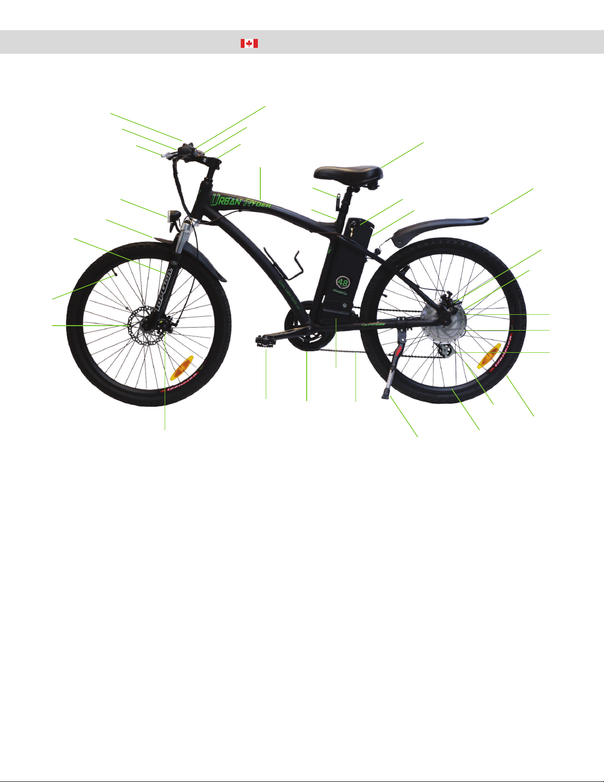
Parts Identification Diagram.......................................................................................................................................... 3
Assembly Instructions...................................................................................................................................................4
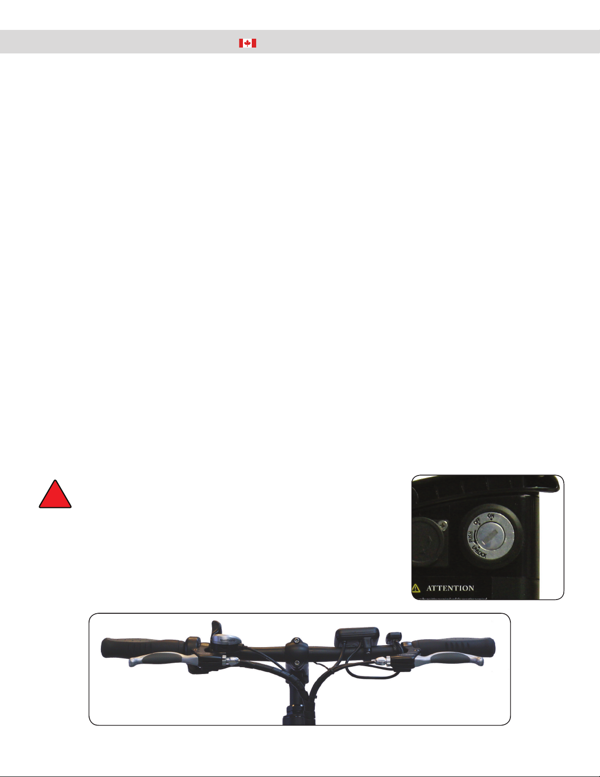
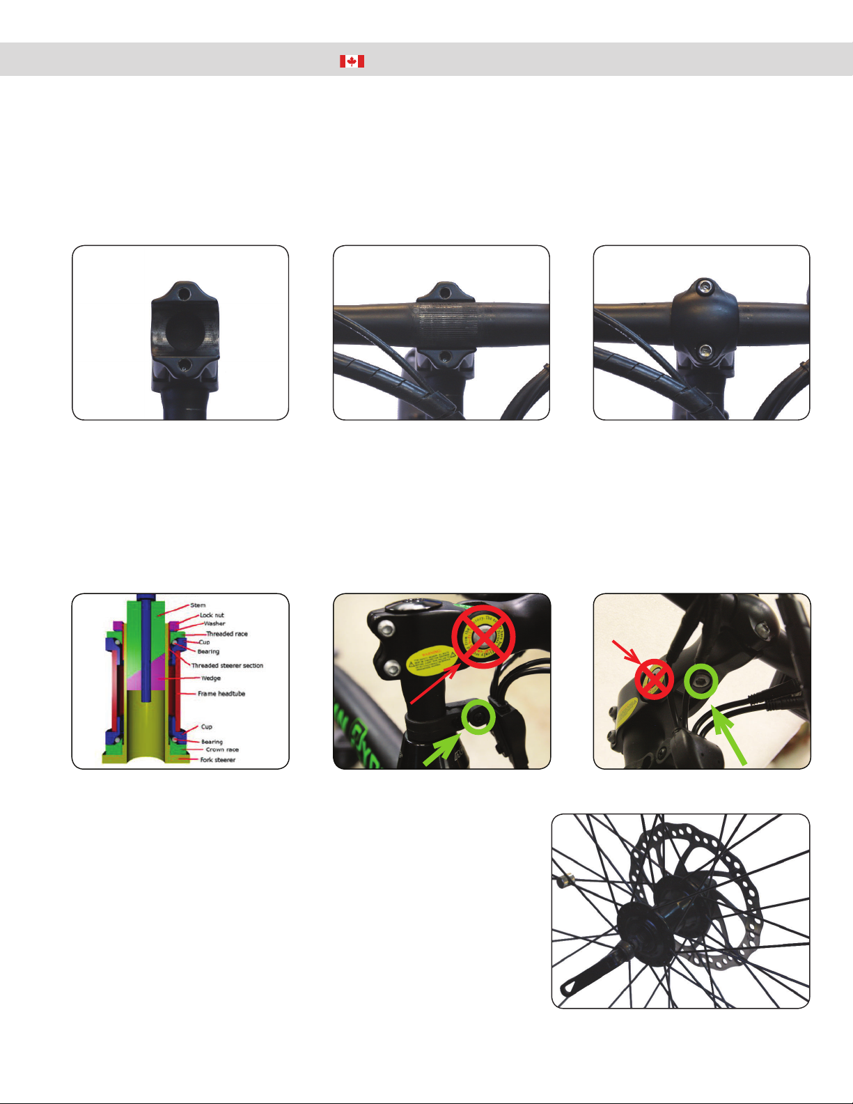
Assembly: Handlebars.........................................................................................................................................5
Assembly: Front Wheel & Pedals ........................................................................................................................6
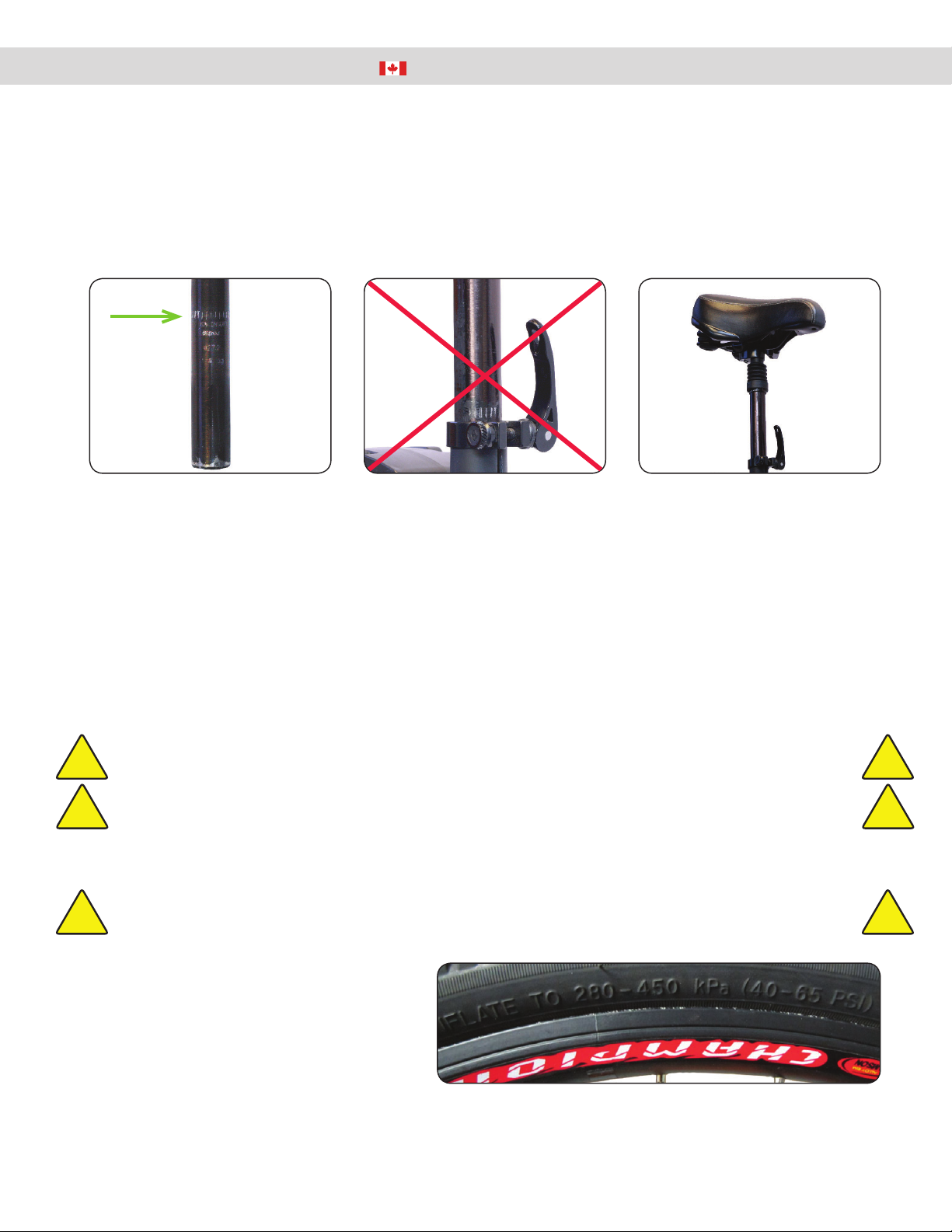
Assembly: Seat Installation & Tire Pressure........................................................................................................ 8
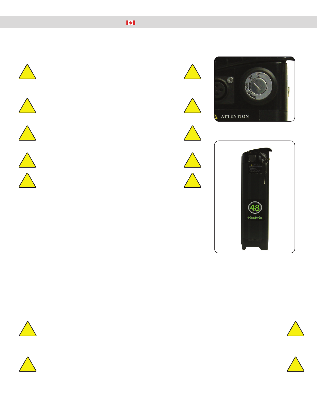
Urban Ryder™ Operation: Battery Removal & Installation, Precautions, Charging, and Storage.........................9
Removal & Install the Battery ..............................................................................................................................9
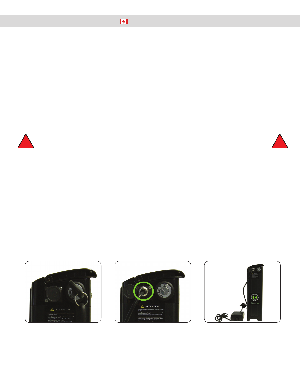
Charging the Battery.......................................................................................................................................... 10
Long Term Battery Care..................................................................................................................................... 11
Extending the Life of Your Battery ..................................................................................................................... 12
Urban Ryder™ Operation: System & Battery Power “ON/OFF” ..............................................................................13
Introduction ........................................................................................................................................................13
Power Up Your E-Bike .......................................................................................................................................13
Using the King Meter®.......................................................................................................................................14
Time Setting............................................................................................................................................... 14
Top Riding Speed ...................................................................................................................................... 14
Display Units..............................................................................................................................................15
Wheel Diameter Setting.............................................................................................................................15
Backlight Brightness ..................................................................................................................................15
Exit Settings...............................................................................................................................................15
Normal Operation of E-Bike...............................................................................................................................15
Power OFF ................................................................................................................................................15
Speed Display............................................................................................................................................15
Pedal Assist Level & Throttle Power Off/On Selection.......................................................................................16
King Meter® Display Backlight & Bike Headlight.......................................................................................16
Distance & Time Display............................................................................................................................16
Battery Capacity ........................................................................................................................................16
Display Malfunction Codes ........................................................................................................................17
Button Battery Replacement......................................................................................................................17
Pedal Assist & Thumb Throttle...........................................................................................................................17
Braking System..................................................................................................................................................17
Urban Ryder™ Operation: Pre-Ride Checklist ..........................................................................................................18
Pre-Ride Checklist & Familiarization Before Your First Ride ............................................................................. 18
Operation of Power Assisted Bicycle Controls...................................................................................................18
“10 Point” Check List Before Your First Ride and Every Ride After ................................................................... 18
Urban Ryder™ Operation: Usage ...............................................................................................................................19
Urban Ryder™: Troubleshooting................................................................................................................................ 20
Urban Ryder™: Care & Maintenance..........................................................................................................................21
Transporting an Electric Bicycle......................................................................................................................... 21
Cleaning.............................................................................................................................................................22
Keys for the Battery ...........................................................................................................................................22
Locating Your Serial Number .............................................................................................................................22
Urban Ryder™: Warranty.............................................................................................................................................23
WARRANTY REGISTRATION INFORMATION CARD .................................................................................................24

3
1-855-GRN-RYDE (1-855-476-7933) www.greenlightcycle.com
USER MANUAL - URBAN RYDER™ PARTS IDENTIFICATION DIAGRAM
Parts Identification Diagram
1. Tektro® Front Disc Brake
2. Tire Valve Stem
3. Front Suspension
4. Front Fender
5. Front Light
6. Brake Levers
7. King Meter® LCD Display
8. Bell
9. Thumb Throle
10. ShiLever
11. Handlebar
12. Frame
13. Seat Post
14. Quick Release Seat Lock
15. Seat
16. Baery Key
17. Baery
18. Rear Fender
19. Rear Brake Calliper
20. Tektro® Rear Disc Brake
21. Shimano® Freewheel
22. Hub Motor by 8FUN
23. Shimano® Derailleur
24. Tires
25. Spokes
26. Rims
27. Kickstand
28. Chain
29. Controller box
30. Chain Wheel and Crank
31. Pedals
32. Front Brake Calliper
18
19
20
15
9
17
16
10
11
5
6
7
8
4
3
2
26
27
12
14
13
31
32
28
29
30 25
24
21
22
23
1

4
USER MANUAL - URBAN RYDER™
www.greenlightcycle.com1-855-GRN-RYDE (1-855-476-7933)
ASSEMBLY INSTRUCTIONS
Congratulaons on receiving your Urban Ryder™ Electric Bicycle! If for any reason you do not have the proper tools or
are not confident in safely assembling the bike yourself, we recommend that you take the bike to a local bike shop for
assistance or have them assemble it. We suggest taking all bikes in for a safety check and tune up before riding. Always
wear a helmet when riding.
Open the box from the top by cung the 3 bands and the packaging tape. Carefully remove the 3 Styrofoam packing blocks.
Remove the front wheel before removing the bicycle. Remove the bicycle by liing it straight out of the box (this may
require 2 people). Be careful not to scratch yourself or the bike on the carton staples. Stand the bike on a clean flat surface
and remove the Styrofoam packing material strap ed to the frame and various parts. Be careful not to scratch the bike or
cut yourself when snipping the strap es. Be sure to keep any small packages of parts and paperwork that come with the
bike. Check all contents to ensure you have each part required for assembly.
Box Contents:
1 x Bike Frame with Rear Wheel Aached
1 x Front Wheel
2 x Pedals (Le& Right)
1 x Lithium Baery 48 Volts 13 Ah
2 x Baery Keys
1 x 120 Volt Charger
1 x Seat
1 x Tool Kit: 5 x Hex Wrenches (2 mm, 3 mm, 4 mm, 5 mm, 6 mm)
3 x Wrenches, double sided (8 mm & 10 mm, 13 mm & 15 mm, 14 mm & 17 mm)
1 x Screwdriver, double sided (star & slot configuraon)
1 x King Meter® Owner’s Manual
1 x Shimano® Gear and Tektro® Brake Data Sheets
1 x Green Light Cycle Owner’s Manual
Now that you have your bike out of the box and unpacked, it is me to charge the baery. Please refer to the Baery
Removal & Installaon, Precauons, Charging, and Storage instrucons on page 9. It is beer to remove the baery from
the bike for the first charging as this will make the bike assembly easier, with no cords in your way.
Assembly Instructions
Unlock the baery with the key by inserng the key in the lock, close to the seat.
Push the key to depress the lock into the baery and turn the key one half turn
counter clockwise to unlock the baery slide pin and then remove the key. Pull
the baery straight up by the folding handle to remove from the bike. Follow the
charging instrucons to complete the baery to full charge. Reinstall the baery into
the bike aer you have completed the bike assembly.
WARNING: Please keep the keys to your electric bicycle in a safe place.
Each set of keys are unique to your parcular electric
bicycle and we do not keep a copy of your key on file!
!
Battery Lock
1. Handlebars
Fig. 1.1 Handlebars (viewed from the front of the bike)
Rear brake
(Right, Crank side)
Front brake
(Left side)

5
1-855-GRN-RYDE (1-855-476-7933) www.greenlightcycle.com
USER MANUAL - URBAN RYDER™ ASSEMBLY: HANDLEBARS
Assembly: Handlebars
Install the handlebars by loosening the stem wedge bolt and turning the handlebar stem to face the front of the bike.
Remove the stem faceplate and 2 bolts. Turn the handlebar to ensure that the wiring is not twisted and flows upward
toward the handlebars without kinking (Fig. 1.1). Place the handlebars in the half round stem cut-out (Fig. 1.2) making sure
that the grooves (splines) are aligned correctly, in the centre of the cut-out (Fig. 1.3). Replace the faceplate and ghten the
bolts evenly so that the faceplate sits flat over the handlebar (Fig. 1.4). Lastly, align the handlebars 90° to the front wheel
and ghten the handlebar stem bolt. Also see adjusng handlebars below.
Fig. 1.2 Handlebar Stem
Cut-out
Fig. 1.3 Handlebar Stem With
Handlebar Inserted
Fig. 1.4. Handlebar Faceplate
With Tightened Bolts
Fig 1.8. Quick Release Lever, Front
Wheel
Quick Release Lever on the Front Wheel
Urban Ryder™ uses a Quick Release Lever to lock the front wheel into the
fork dropouts (Fig. 1.8). Quick Release Levers are safe and convenient
when adjusted properly. Before riding your bicycle you must understand
how they work and how to use them properly to prevent serious injury
or death from a fall.
Quick Release Levers use a cam acon to clamp the front wheel in place.
Due to their adjustable nature, it is crical that you understand how they
work, their proper use, and how much force is needed to secure them
correctly.
Fig. 1.5 Wedge Diagram Fig. 1.6 Tighten Cable Screw
(green)
DO NOT
TOUCH
Fig. 1.7 Adjust Handlebar
Angle (green)
DO NOT
TOUCH
If you receive your bike with the handlebars stem out of the steering tube, then remove the protecve cover on the stem
wedge. Apply a bit of grease or oil to the stem wedge to help it insert into the rubber stem seal on the steering tube. Wiggle
and turn the stem at the same me as you slide it down the steering tube. Insert wedge past or up to “MAX HT” mark
on stem. Align the handle bars perpendicular to the front wheel and ghten the Allen head wedge expander bolt. Adjust
the angle of the handlebar with the Allen bolt, located under the handlebar base (Fig. 1.7). Idenfy the black wire loom
clamp on the handlebar stem and remove the screw. Move the wire loom to the side of the clamp and insert the screw and
ghten to secure the loom to the stem clamp.

6
USER MANUAL - URBAN RYDER™
www.greenlightcycle.com1-855-GRN-RYDE (1-855-476-7933)
ASSEMBLY: FRONT WHEEL & PEDALS
CAUTION: The full force of the cam acon is needed to clamp the wheel securely. Holding the nut with one
hand and turning the lever like a wing nut, is NOT a safe or effecve way to close a quick release
and will not clamp the wheel safely to the forks.
WARNING: Operang the bike with an improperly adjusted wheel or Quick Release Lever, can allow the
wheel to wobble or fall offthe bicycle. This can cause serious injury or death.
Assembly: Front Wheel & Pedals
2. Installing the Front Wheel
Install the front wheel by first inserng the Quick Release rod into the wheel axel. There are 2 small springs on the Quick
Release rod that have different diameters on each end. Install the springs so that the ends with the larger diameter are next
to the Quick Release and the round nut (Fig. 2.1). Make sure the round black nut is on the disc side of the wheel and the
lock lever is on the opposite side (Fig. 2.3).
Tighten the round nut onto the rod so the rod threads are almost flush with the outside of the nut. Be careful not to cross
the threads and ghten by hand only.
Place the Quick Release Lever in the open posion. Have someone hold and lithe bike by the handlebars to posion the
front wheel into the forks. Make sure that you line up the brake disc with the brake calliper when inserng the front wheel
axel into the fork drop outs (Fig. 2.4). Check to ensure that the axel has engaged all the way into the fork dropouts before
clamping.
Fig. 2.1 Front Wheel Quick Release Fig. 2.2 Quick Release Nut &
Rod Thread
Fig. 2.3 Front Wheel, Quick
Release Inserted Into
Wheel Axle
Fig. 2.4 Front Forks & Brake
Calliper
Fig. 2.5 Quick Release Lever
In Closed Position
! !
It is essenal that you know how to install and remove your wheels safely. If you are unsure ask your local bike shop to
install or assemble your bike and wheels. Understand and apply the correct technique for clamping your wheel in place
with a Quick Release Lever. Before each ride of your bike, check that the wheel is securely clamped properly and the Quick
Release Lever is in the correct posion and locked.
!!
Larger
Diameter to
Outsides

7
1-855-GRN-RYDE (1-855-476-7933) www.greenlightcycle.com
USER MANUAL - URBAN RYDER™ ASSEMBLY: FRONT WHEEL & PEDALS
To ghten the Quick Release and axel into the fork dropout, ensure the Quick
Release is in the open posion with the lever parallel to the ground (the lever
should be at a 90° angle to the forks). With the lever in this posion, ghten
the round nut finger ght. You will not be able to close the lever to the locked
posion yet.
Next, loosen the nut approximately 3 quarter turns, counter clockwise and li
the lever upward to lock the wheel in place. The lever should be almost parallel
to the front fork when locked. If the tension is correct, the lever should close
ghtly. When closing the lever it should leave a clear imprint in the palm of your
hand (Fig. 2.6, the imprint may not be as deep as the hand model’s picture).
When the lever is locked in this posion, parallel to the fork, it will not easily
be opened if it catches on any objects while riding your bike. To increase or
decrease the tension, open the lever and adjust the nut clockwise or counter
clockwise, 1/8 turn at a me. Repeat unl the tension is sufficient. Less than
1/2 a turn on the adjusng nut can make the difference between safe clamping
force and unsafe clamping force. Install the front fender, with the supplied bolts,
in the front forks and at the headlight (Fig 2.7).
3. Pedal Installaon
Note: “L” and “R” (“L” = le& “R” = right) is stamped on the threaded ends of
the pedals (Fig. 3.1). The pedals have opposite thread direcons and must go on
a specific side of the bike. Leand right side of the bike is determined by sing
on the seat.
Assembly: Front Wheel & Pedals
Fig. 2.6 Imprint of Quick
Release Lever After
Correctly Closed
Fig. 3.1 Left & Right Pedals
The LePedal has a reverse, non-standard thread and must be turned counter
clockwise to be screwed in.
The Right Pedal has a standard thread and must be turned clockwise to be threaded in.
Apply some grease to the pedal threads before aaching. Install the Right Pedal to the chain sprocket side of the bike (Fig.
3.2) and the LePedal to the opposite side (same side as the baery key).
Start the pedal threads into the crank arm threads, by hand, at least 4 complete 360° turns to ensure the pedals are not
cross-threaded. Incorrect installaon of the pedals or stripped threads are not covered under warranty. Complete by
securely ghtening with a 15 mm wrench.
WARNING: Poorly ghtened pedals can result in damaging the bicycle, personal injury or death.!!
Fig. 2.7 Forks Secured Onto
Front Wheel
Fig. 3.2 Crank Arm, Right
Pedal Inserted

8
USER MANUAL - URBAN RYDER™
www.greenlightcycle.com1-855-GRN-RYDE (1-855-476-7933)
ASSEMBLY: SEAT INSTALLATION & TIRE PRESSURE
4. Seat Installaon
Idenfy the “Minimum Insert Line” on the seat post (Fig. 4.1). Insert the seat post into the seat tube so the Minimum Insert
Line is not visible (Fig. 4.3). The seat post shamust be installed so that the Minimum Insert Line is at least 1/4 inch below
the Quick Release Lever.
Assembly: Seat Installation & Tire Pressure
Fig. 4.1 Seat Post, “Minimum
Insert Line”
Fig. 4.3 Seat Post Inserted
Correctly, 1/4” Past
“Minimum Insert
Line”
Fig. 4.2 Incorrectly Installed
Seat Post
With the Quick Release Lever in the open posion (the lever should be at a 90° angle to the seat tube), insert the seat post
into the seat tube. Tighten the Quick Release clamp by turning the tension adjusng nut clockwise, with one hand on the
cam lever to keep it from rotang. Lithe Quick Release Lever up to the locked posion.
Grab the seat by the saddle with both hands to aempt to rotate the seat. If you are unable to force the seat out of
alignment with the frame, the clamp is ght enough. If the seat moves out of alignment with the frame, increase the
tension on the adjusng nut approximately a 1/4 turn and try again. The seat height can be adjusted from 34 to 38.5 inches
(863 mm - 977 mm) from the ground or 30.5 to 34.5 inches (774 mm - 876 mm) from the pedals.
Fig. 5.1 Tire Pressure Ratings
CAUTION: Less than 1/2 a turn on the adjusng nut can make the difference between safe clamping force
and unsafe clamping force.
CAUTION: A poorly adjusted seat can result in damaging the bicycle, personal injury or death.
!!
!!
CAUTION: The res have NOT been filled with air to the correct capacity for shipping purposes. !!
5. Tire Pressure
Using a hand pump, fill the res with air to the
rang on the sidewall (Fig. 5.1). We recommend a
hand pump to avoid over inflang the res, which
can easily happen when using a high pressure air
line at a gas staon or automove re store.
The res are rated for a maximum of pressure of
“450 kPa” or “65 PSI”.

9
1-855-GRN-RYDE (1-855-476-7933) www.greenlightcycle.com
USER MANUAL - URBAN RYDER™ URBAN RYDER™ OPERATION: BATTERY
6. Remove & Install the Baery
Urban Ryder™ Operation: Battery Removal & Installation, Precautions, Charging, and Storage
CAUTION: Fully charge the baery before the first use!
Failure to do this can result in decreased baery
performance for the life of the bike and void your
baery warranty.
CAUTION: Do not aempt to open or repair your baery or
charger. If you need another baery or charger
contact your dealer or Green Light Cycle Ltd.™
CAUTION: Do not touch the baery sockets or blades with
your hands, any metal object or other material that
conducts electricity.
CAUTION: Never put the baery or charger in reach of children.
CAUTION: Do not use any charger except the one that came
with your Urban Ryder™ Electric Bike.
Lithium Baery Precauons
!
!
!
!
!
!
!
!
!
!
Unlock the baery from the baery slide by inserng the baery key into the lock,
located on the top of the baery near the handle (Fig. 6.1). Push the key inwards to
depress the lock into the baery and turn the key one half turn counter clockwise
to unlock the baery slide pin. Remove the key before trying to lithe baery
away from the bike. Remove the seat to slide the baery straight up and out of the
baery slide, using one hand on the folding handle and the other hand to hold the
bike steady.
Install the baery in the reverse order of removal. Ensure the top of the controller
box, where the base of the baery rests, is clear of any dirt or debris. Align the
baery base so that it inserts into the baery slide and with the half round grooved
cradle against the seat post tube. Insert the baery gently unl the base rests
ghtly on the control box and the connecng blades are inserted firmly into the
baery base sockets. The blades and sockets are greased to make removal and replacement easier. Lubricate as necessary.
Do not use excessive force to fit the baery into the base, as it could damage the connecon sockets or blades. Be sure to
always lock the baery aer placing in the cradle.
CAUTION: Do not aempt to open or repair your baery. This may cause electrical shock or fire and will
void your warranty. Should you have a problem or need another baery contact Green Light
Cycle Ltd.™ Should your baery become hot, emit smoke or unusual odors, remove the baery
to a dry area outside immediately.
CAUTION: Fully charge the baery before the first use! Failure to do this can result in decreased baery
performance for the life of the bike and void your warranty.
!
!
!
!
Fig. 6.2 Battery
Fig. 6.1 Battery Lock

10
USER MANUAL - URBAN RYDER™
www.greenlightcycle.com1-855-GRN-RYDE (1-855-476-7933)
URBAN RYDER™ OPERATION: BATTERY
As lithium baeries do not suffer from Memory Effect, it is not required for the baery to be empty to begin a charge. Top
up charging every me you have completed your ride is recommended. A new baery might take 2 or 3 charges before it
performs at its full capacity. All baeries have a finite life cycle and eventually lose storage capacity below a useful level.
Kept in good condion, a lithium baery will perform at least 300 to 900 full charge cycles with a retenon of 70% from
its original capacity. Small top up charges count fraconally towards a single full cycle charge. The baery may be charged
on or offthe bike. Always charge the baery with the key in the “OFF” posion. Never charge a hot baery or immediately
aer a long ride; let the baery cool for approximately 1 hour prior to charging.
Do not leave the charger plugged into the baery for long periods of me, as this can damage the baery. Always charge
the bike in a dry, clean place. Keep the charger dry and clean. Avoid storing your baeries in extreme temperatures, hot or
cold, and keep in a cool dry place. Always plug the baery charger into a grounded ELECTRICAL circuit.
The baery can be used in any weather between 1°C to 38°C. Extreme heat or extreme cold can shorten the baery range.
Try to avoid fully discharging the baery. It may be possible aer the baery is discharged to turn offthe bike, wait a few
seconds, and turn it back on to get a small amount of power. This “pulsing” (turning offand on) will permanently damage
the baery. Lithium baeries prefer frequent paral discharge charge cycles rather than fewer, full, deep cycle charges.
To prevent premature failure of your baery and for your warranty to remain in effect, you must charge and discharge the
baery at least once per month.
7. Charging the Baery
The supplied baery is a Lithium, 48 Volts and 13 Amp hours. Check to ensure that the charger voltage is correct for your
ba
ery. The charger should read “Output 55VDC 2A”. This is an output for a power source of approximately 120 Volts. If the
charger output reads greater than or less than 55, it means that the output of the power source is greater or less than 120V
respecvely. Only use a wall receptacle with a grounded circuit to plug your charger into.
WARNING: Never charge the baery outside in wet weather, as there is a chance of electrical shock,
electrocuon, and death.
! !
Urban Ryder™ Operation: Battery Removal & Installation, Precautions, Charging, and Storage
Fig. 7.1 Battery Key - OFF Fig. 7.3 Battery & Charger
Fig. 7.2 Battery Charging
Port

11
1-855-GRN-RYDE (1-855-476-7933) www.greenlightcycle.com
USER MANUAL - URBAN RYDER™ URBAN RYDER™ OPERATION: BATTERY
• Turn the key to “OFF” and remove the key from the baery (Fig. 7.1).
• Locate the charging port on the baery on the top right side and turn the
dust cover to the side to expose the charging port (Fig. 7.2).
• Insert the baery charger plug into a 120 Volt wall socket receptacle with
a grounded circuit. Do not use an extension cord. The light on the charger
should illuminate to steady green.
• Insert the round plug of the charger into the baery charging port, the LED
should illuminate to steady red (Fig. 7.5).
• When the light on the charger changes to a steady green, the baery is
charged (Fig. 7.4). Unplug the charger from the wall receptacle and then
from the bike baery. Always disconnect the plugs in this order.
A full charge will take approximately 4 to 6 hours to complete. Avoid
overcharging and damaging the baery. When the light changes to steady
green, the charger is in “trickle mode”. Avoid prolonged charging in this mode
as it may damage the baery. Maximum connuous charging me is 24
hours.
The charger will become warm during charging so keep the charger away
from any flammable materials. The charger may reach temperatures up to
185°F/85°C during normal charging. Never enclose the charger or put anything
Fig. 7.4 Battery Charged -
Green LED
Fig. 7.5 Battery Charging -
Red LED
on top of it when charging. The charger must be well venlated.
If the charger emits a peculiar smell or the temperature is too high, stop charging immediately! Do not drop or damage
the charger. Avoid any contact with water when charging your baery. If a plug or socket gets wet, dry it completely before
using. Always use the charger according to the instrucons. Improper use or aempng to open/repair the charger will void
your warranty.
Urban Ryder™ Operation: Battery Removal & Installation, Precautions, Charging, and Storage
Fig. 7.6 USB Port
Charge Your Smartphone
Want to charge your device on the go? Our new 13amp baeries come with a
USB charging port (max. 1 amp) so you can charge your smartphone while you’re
navigang your ride! Just remember to keep your eyes on the road and not on
your device!
USB charging cable not included.
Remove the protecve cover from the USB port (max 1 amp). Determine the
correct orientaon of your USB charger cable and insert it into the USB port on
the Urban Cruzer baery. Plug your charging cable into your smartphone device
and turn the E-bike baery key to the “ON” posion. Check the baery indicator
on your smartphone to determine that it is now charging. Be sure to check your
smartphone’s rated amperage prior to charging it with your E-bike baery. Do not
aempt to charge any device other than a smartphone rated for 1 amp.

12
USER MANUAL - URBAN RYDER™
www.greenlightcycle.com1-855-GRN-RYDE (1-855-476-7933)
URBAN RYDER™ OPERATION: BATTERY
Long Term Baery Care
When storing your baery for a long period of me (more than 60 days):
Charge the baery to about 75%, then recharge every 60 days as needed to maintain this level. Allowing your baery to sit
for longer than 60 day periods in a discharged state could lead to permanent capacity loss and void your warranty.
• Ideally baeries should be stored between 50°F/10°C to 80°F/27°C. Avoid long periods of freezing and extreme heat,
104°F/40°C or higher.
• Do not leave the baery in direct sunlight for prolonged periods of me.
• Keep the bike in the shade during summer months.
• Store the baery in a clean dry locaon with low humidity condions.
• Do not allow the baery to accumulate condensaon such as dew, heavy fog or rain, as this could cause shorng.
• Do not clean or wash the baery with pressurized water; wipe with a damp cloth only and towel dry completely.
• Do not connect the baery to the bike in wet condions.
• Do not submerse the baery in water.
Extending the Life of Your Baery
To help extend the life of the baery, assist the bike as much as possible. A few ps to prolong the baery life during certain
condions are as follows:
• Always turn your baery key “OFF” aer each use, as the electrical system will sll draw minute power from your
baery.
• Charge the baery frequently. If possible, before using 50% of the power.
• When starng from dead stop, use the pedals to bring the bike up to speed.
• When riding uphill or against the wind, pedal to supplement the baery power.
• When the baery meter indicates the voltage is low, switch to the lowest pedal assist mode or 0 to avoid using the
baery and shortening the baery life.
• Do not ride your bike in heavy rain storms, thunder showers, or extreme condions.
• When riding downhill, you must have the key and King Meter® Controller in the “ON” posion, as the motor will
generate electricity. Having the key in the “OFF” posion may damage your baery, controller, or electrical parts, and
may void your warranty.
• Store your baery in a locaon with a temperature above 50°F/10°C for best results.
Urban Ryder™ Operation: Battery Removal & Installation, Precautions, Charging, and Storage

13
1-855-GRN-RYDE (1-855-476-7933) www.greenlightcycle.com
USER MANUAL - URBAN RYDER™ URBAN RYDER™ OPERATION: SYSTEM
Introducon
To ensure beer performance of your E-Bike, please read through the J-LCD product introducon carefully before using or
starng your bike.
Familiarize yourself and become competent with the Funcon Summary, Buon Definion, and Introducon of User
Sengs on the King Meter® Display before your first ride. Stay safe: know and understand how the bike operates before
riding!
The user sengs include: set local me, top riding speed, Imperial or Metric system, wheel size, and LCD backlight
brightness.
The LCD display indicates: baery capacity, me, motor power rao, riding speed, total riding distance, trip distance,
6 km/h power assist walk mode, and malfuncon codes of the electrical controls and systems.
The “30 Buon”, with up down arrows and mode buon, controls the E-Bike’s power “ON/OFF”, programming the display,
and sengs.
8. Power Up Your E-Bike
To turn on the bike baery, turn the key on the baery to the “ON” posion clockwise 1/8 turn unl you hear the click and
the key stops (Fig. 8.1). The baery power is now turned on.
Fig. 8.2 Keep Break Lever
Depressed
WARNING: DO NOT illuminate the King Meter® if you are NOT on the bike and ready to ride forwards. This
avoids false starts and crashes!
WARNING: ALWAYS REMEMBER to hold a brake lever depressed firmly when geng on and offthe bike
SO THE BRAKE LEVER KILL SWITCH can stop the electrical flow to the motor (Fig. 8.2).
This avoids false starts and crashes! This will help reduce accidents caused by pressing the
thumb throle accidentally or iniang the pedal assist before you are ready to ride.
WARNING: Always turn the key “OFF” immediately aer you dismount from the bike (Fig. 8.3).
!
!
!
!
!
!
Urban Ryder™ Operation: System & Battery Power “ON/OFF”
Fig. 8.1 Battery Key - ON Fig. 8.3 Battery Key - OFF

14
USER MANUAL - URBAN RYDER™
www.greenlightcycle.com1-855-GRN-RYDE (1-855-476-7933)
URBAN RYDER™ OPERATION: SYSTEM
9. Using the King Meter®
To turn the bike motor on and illuminate the King Meter® Display. Idenfy the “30 Buon” on the handlebar, beside the
King Meter® Display.
Hold down the centre “MODE” buon between the UP and DOWN arrows for approximately 2 seconds, unl the display
illuminates (Fig. 9.2).
When the King Meter® display is illuminated and the “ASSIST” indicates a number (1 to 5), the motor can be started by
actuang the thumb throle or the pedal assist.
For safety, use the DOWN arrow to set the “ASSIST” to “0” while programming the King Meter® (Fig. 9.3).
Urban Ryder™ Operation: System & Battery Power “ON/OFF”
Fig. 9.2 Hold Down “MODE”
Button for 2 Seconds
Fig. 9.1 King Meter®
Display, OFF
Fig. 9.3 King Meter® Display,
Set “ASSIST to “0”
While Programming
Aer LCD display lights up, hold the UP and DOWN arrows at the same me for 3 seconds; the LCD will display the default
seng mode.
Time Seng
Aer entering into the seng mode, first set the hour by using the up and down arrows. Press the MODE buon to confirm
the seng. Next, set the minutes using the UP and DOWN arrows. Press the MODE buon to confirm the seng.
Top Riding Speed
The default seng on the top riding speed has been set to 32 km per hour.
The top riding speed can be set from 10 km/h to 32 km/h by using the UP and
DOWN arrows. Press the MODE buon to confirm the seng. The top riding
speed in Canada is 32 km per hour in all cies, streets, and highways (Fig.
10.1). Check with Police to determine the local laws and bylaws to confirm the
maximum legal speed seng in your riding area.
! !
WARNING: Do not exceed the top riding speed of 32 km per
hour as you will be breaking the E-Bike speed limit
law and pung yourself in personal danger which
may result in prosecuon, severe injury, or death.
Fig. 10.1 Maximum Legal
Riding Speed In
Canada
MAXIMUM
32
km/h

15
1-855-GRN-RYDE (1-855-476-7933) www.greenlightcycle.com
USER MANUAL - URBAN RYDER™ URBAN RYDER™ OPERATION: SYSTEM
Display Units
Press the Up or Down Arrow to choose between Imperial or Metric display units. Press the Mode buon to confirm the
seng.
Wheel Diameter Seng
Press the Up or Down Arrow to choose a corresponding wheel diameter to ensure the accurate display of speed and
distance on the LCD. The Urban Ryder™ wheel size is 26 inches. Press the Mode buon to confirm the seng.
Backlight Brightness
Press the Up or Down Arrow to modify the backlight brightness. You can choose from levels 1 to 3. Level 1 is the minimum
brightness and uses the least power from the baery. Level 3 is the brightest and will use more power from the baery.
Press the Mode buon to confirm the seng.
Exit Sengs
When in a seng mode, press the Mode buon within 2 seconds of making your choice to confirm. Press and hold the
Mode buon for more than 2 seconds to save the current sengs and exit the seng interface (Fig. 10.2).
The King Meter® is now set.
10. Normal Operaon of the E-Bike
Before you turn on the baery power to ride the bike, sit on the bike seat and
assume a comfortable posion to ride forward.
With the key in the “ON” posion, press the Mode buon and the display will
illuminate. The motor is now powered. Keep one hand brake depressed aer
turning on the King Meter® unl you are ready to ride forward.
When the King Meter® is turned on (display illuminated), holding or pressing
the Mode buon again will turn the power to the bike motor off. If no controls
are pressed for approximately 5 to 7 minutes and the bike is not in moon, the
King Meter® will power off.
Power OFF
In the power “OFF” state, the King Meter® uses minimal power to keep the clock running. It is advisable to turn the key on
the baery to the “OFF” posion to conserve energy and keep your bike and the people around you safe.
Speed Display
When the King Meter® illuminates, the display will automacally show the current speed. By pressing and holding the Up
Arrow for 2 seconds, the display will show the average (AVG) speed during this ride. Press and hold the Up Arrow again and
the display will change to show the maximum (MAX) speed during this ride. Repeat to show current speed again.
Fig. 10.2 Hold down “MODE”
Button for 2
Seconds
Urban Ryder™ Operation: System & Battery Power “ON/OFF”

16
USER MANUAL - URBAN RYDER™
www.greenlightcycle.com1-855-GRN-RYDE (1-855-476-7933)
URBAN RYDER™ OPERATION: SYSTEM
11. Pedal Assist Level & Throle Power Off/On Selecon
When the King Meter® is illuminated, pressing the UP or DOWN Arrows will
change the output power of the motor for the pedal assist, or turn offthe
power to the motor completely (set assist to “ASSIST 0”). The pedal assist power
ranges form Level 1 to 5. Level 1 is the minimum power the motor will supply by
turning the pedals and Level 5 is the maximum power (100%). The default level
when the King Meter® is started is Level 1.
When the “ASSIST” is set to “0”, no power will be supplied from the motor by
pedalling or by using the thumb throle. Use this mode when you want to ride
the bike without any motor assist.
The thumb throle (Fig. 11.1) allows you to immediately increase the power to
the motor with the touch of your thumb, similar to the throle on a motorcycle.
Increasing pressure on the thumb throle will increase the power and speed.
The “ASSIST” sengs (Level 1 to 5), will not adjust the power to the thumb
throle.
When the “ASSIST” selecon is set at “0”, the thumb throle is “OFF”. When the
assist selecon is set at Level 1 to 5, the thumb throle is “ON”.
King Meter® Display Backlight & Bike Headlight
To turn the backlight and bike headlight “ON” and “OFF”, hold the UP Arrow
and MODE buon together for 3 seconds (Fig. 11.2). Use this feature at night
or in low light condions to illuminate the display and your headlight for safe
riding.
Distance & Time Display
When the King Meter® is illuminated, it will display the odometer seng “ODO”
which is the total distance the bike has been ridden. Press the MODE buon to
change the display to show the riding distance for this trip.
Baery Capacity
When the baery charge is full, the baery symbol will show 5 segments
illuminated in black. As the baery is consumed, the segments will disappear to
indicate the amount of power available, unl all the segments have disappeared
and the baery symbol is white, indicang the level is severely low.
When the baery symbol is completely white, it will begin to flash. A flashing
baery symbol means that you need to recharge immediately. We advise that
you do not use the electric power to assist your bicycle in this state. Set the
“ASSIST” to “0” and use only your own pedal power unl you can recharge the
baery (Fig. 11.3). This will help give your baery a longer life.
Fig. 11.2 Backlight & Bike
Headlight, Hold
Down “MODE & UP
Arrow Button for 3
Seconds
Fig. 11.1 Thumb Throttle
Fig. 11.3 King Meter®
Display, Set ASSIST
to “0” While
Programming
Urban Ryder™ Operation: System & Battery Power “ON/OFF”

17
1-855-GRN-RYDE (1-855-476-7933) www.greenlightcycle.com
USER MANUAL - URBAN RYDER™ URBAN RYDER™ OPERATION: SYSTEM
Display Malfuncon Codes
Should there be something wrong with the electronic controls, motor, or baery, the King Meter® will automacally show
an error code below:
Code Definion
21 Electrical Current Abnormality - Check to see if all plugs are connected properly or have been damaged.
22 Throle Abnormality - This is oen a result of holding down the thumb throle while turning on the E-bike.
23 Motor Open-Phase - This means there is a connecon error between the plug and the motor. Check all plugs.
24 Motor Hall Signal - This means there is a connecon error between the motor and controller. Check all plugs.
25 Brake Abnormality - This is oen a result of holding down the brake handle while turning on the E-bike.
30 Communicaon Abnormality - This means there is a connecon error between the display and controller. Check
all plugs.
baLU Buon Baery Low - This means that the buon baery in King Meter® needs to be replaced.
Buon Baery Replacement (Prior to 2017)
Fig. 12.1 Thumb Throttle
To replace the display baery, first detach the display from the handlebar. Remove
the baery cap and old baeries. The baery model is # CR2032. Install the
new baery, ensuring it is in the correct posion (+/-). The life of the baery is
approximately 2 years. Aer replacing the baery you may need to reset the me.
12. Pedal Assist & Thumb Throle
With the King Meter® illuminated and “ASSIST” set from Level 1 to 5, the thumb
throle is acve (Fig. 12.1). When pressed downward, the bike will drive forward.
The thumb throle delivers up to 100% of the motor power depending on how
much the lever is depressed.
The Pedal Assist funcon watches the rotaon of the pedals to deliver power to
the motor (Fig. 12.2). Depending on which level the “ASSIST” is set to (Level 1 to
5), the King Meter® will determine how much power the motor delivers to move
the bike forward. Using the “ASSIST” on the lowest seng will consume the least
amount of power from the baery and give you the longest riding distance.
13. Braking System
The bike is equipped with two brake levers located on the leand right sides of
the handlebar. To stop the bike, depress both break levers.
In USA-STANDARD configuraon, the lebrake lever controls the front wheel
and the right brake lever controls the rear wheel.
Urban Ryder™ Operation: System - System and Battery Power “ON/OFF”
WARNING: There are 2 styles of brake handle configuraon: MOTO and USA-STANDARD. Review and
understand your braking system, brake handle configuraon and which handle controls
the front wheel or rear wheel before riding your bike. Use the brake handles to control
your speed appropriate to riding condions and remember that you are the only person
responsible for your personal safety. Adjust and service your brakes as necessary.
! !
Fig. 12.2 Pedal Rotation

18
USER MANUAL - URBAN RYDER™
www.greenlightcycle.com1-855-GRN-RYDE (1-855-476-7933)
URBAN RYDER™ OPERATION: PRE-RIDE CHECKLIST
Pre-Ride Checklist & Familiarizaon Before Your First Ride
We want you to have a fun ride, but also a safe one. Carefully read the following informaon, even if you are an
experienced rider. The Urban Ryder™ can quickly reach high speeds; cauon must be exercised when operang the bike.
Green Light Cycle Ltd.™ is the producer of this Owner’s Manual and assumes no responsibility for your personal safety. The
bike manufacturer assumes that you already know how to ride a bicycle and gives no instrucon on basic riding skills, rules
of the road, Federal and Provincial Laws, or Motor Vehicle Regulaons.
Urban Ryder™ Operation: Pre-Ride Checklist
! !
! !
! !
! !
! !
WARNING: You are the only person responsible for your personal safety when operang this electric bike
and you must be aware of its operaon in any riding condions. Familiarize yourself unl you
understand and are competent with this bike’s controls and braking systems before operang or
riding.
WARNING: Wear safety equipment when operang any bike. Dress to be seen with high visibility reflecve
clothing.
WARNING: Is your helmet on? Remember, bike helmets can save lives and help to avoid serious injury.
Always wear an approved helmet when riding this bike or any bike.
WARNING: Never operate electronic handheld devices like cell phones, headsets or computers while riding.
WARNING: Do not drink and ride.
Operaon of Power Assisted Bicycle Controls
Bell - Signals to traffic you are there.
Pedals - Drive the bike forward.
Headlight - LED light controlled by pressing the Mode and Up Arrow buons at the same me.
Bike Keys - Turns the baery electrical supply off/on to the bicycle controls and locks the baery in place
on the bike.
King Meter® - Controls the Pedal Assist speed level, records trip informaon, controls the headlight, and
turns thumb throle “ON/OFF”.
Handlebars - Contain the controls (King Meter®, Brakes, Gear Shier, Bell, & Thumb Throle), and steer the
bike leor right.
Brake Handles - Stop the bike by squeezing the handle toward the hand grips. The brake handles also have kill
switches built in to them that stop the electricity flow to the motor, turning it off. Any me the
brakes are applied, the motor will stop pushing the bike in a forward direcon.
Shimano® 7 Speed Shier - Switches between gears on the rear wheel to adjust ease of pedaling in order to climb grades
or ride at different speeds.
“10 Point” Check List - Before your First Ride and Every Ride Aer
1. Baery is connected, locked, and charged.
2. Electrical devices are working correctly.
3. All nuts and bolts are
ght.
4. The front and rear wheels are secured to the bike frame and cam locks are ght.
5. The res are filled to the correct pressure, as indicated on the re side wall.
6. The brakes are adjusted and operang correctly, including the brake kill switches.
7. The seat is locked and the seat stem is adjusted to the correct height.
8. Handlebars are ghtened firmly.
9. Chain and crank arms run smoothly and are lubricated.
10. The rider is wearing appropriate safety gear, including: high visibility reflecve clothing, helmet, and eye protecon.

19
1-855-GRN-RYDE (1-855-476-7933) www.greenlightcycle.com
USER MANUAL - URBAN RYDER™ URBAN RYDER™ OPERATION: USAGE
Usage
• Wear shoes that grip firmly to the pedals, no bare feet.
• Wear high visibility clothing no loose clothing and dress to be seen.
• Always wear an approved bicycle helmet and eye protecon.
• Keep your speed levels appropriate to road condions and speed limits.
• Ride slow on wet or slippery surfaces and brake sooner than ancipated.
• Avoid cycling at night or in poor weather such as fog, rain, snow, or icy condions.
• Familiarize yourself with usage of the bike and know how to maintain it.
• Be familiar with traffic signs, rules and laws, and be aware of other traffic.
• When possible, ride in bike lanes and in the correct direcon of traffic flow.
• Do not ride on the sidewalk and dismount when using pedestrian crossings.
• Keep both hands on the handlebars when riding.
• Keep in mind that other traffic may underesmate the speed of an electric bicycle.
• Ride defensively, keep alert, and have fun!
The Urban Ryder™ Electric Assisted Bicycle has a 48 volt baery at 13 amp hours, supplying the power to a 500 waelectric
brushless 8FUN rear hub motor. This is a powerful electric assisted bicycle in a pass-through shaped frame and special care
must be taken when geng to know it. You will be riding faster than you think!
Because the bike can quickly reach high speeds, you need to exercise cauon when operang this E-Bike. Even though you
may be an experienced bicycle rider, your first ride should be in an area without traffic or other hazards.
We suggest that you ride the bike as a bicycle with no power assist turned on (set “ASSIST” to “0”), to familiarize yourself
with the bike’s extra weight and slow handling and stopping. Test the bike’s braking ability to determine your stopping
distances. Once you become confident in your riding and braking ability, set the assist level to the lowest seng, Level 1,
and begin riding the bike.
When you feel confident and familiar with the feel from the powerful 500 wamotor, try using the thumb throle and
higher Assist Levels. Pay special aenon to the weather and road condions when learning to ride your E-Bike. Wet roads
require longer stopping distances than dry roads. Always look ahead when riding to give yourself me to stop in emergency
situaons. Remember that pedestrians may not be able to hear or see you approaching from behind. Slow down and use
extra cauon when passing foot or vehicle traffic, parked cars, or other cyclists. Do not be afraid to use your bell, it’s there
to signal “Here I Am”.
Once you have mastered the Urban Ryder™ Electric Assisted Bicycle, your commute to work or leisure bike rides will
become an easy and fun experience. E-Bikes are a great way for persons recovering from heart condions to engage in
cardio exercise. When you get red you can use the power assist to supplement your pedalling power or simply bring you
home. This way you will not stress your body and can build your strength gradually to improve your fitness or your road to
recovery.
The Green Light Cycle Ltd.™ Team wishes you safe riding and beer health.
Thank you for your purchase,
Urban Ryder™ Operation: Usage
7ȱɏ*Ⱦȭʑɚ7Hʋə

20
USER MANUAL - URBAN RYDER™
www.greenlightcycle.com1-855-GRN-RYDE (1-855-476-7933)
URBAN RYDER™: TROUBLESHOOTING
Urban Ryder™: Troubleshooting
Magnet on front wheel spoke is not aligned to King Meter®
receiver on right fork. The magnet should line up to the
round boom of the receiver.
“ASSIST” is set to 0.
Baery level is too low.
Brake lever is slightly depressed.
Controller is defecve.
Thumb throle is defecve.
Thumb throle has bad connecon.
Controller is defecve.
Pedal Assist connecon to controller.
Pedal Assist sensor is defecve.
Brake lever has not released.
Brake lever kill switch is defecve.
Controller is defecve.
Check re pressure.
Check brake calliper is scking closed.
Check baery is charged.
Wire is loose or disconnected at light.
LED’s in headlight are defecve.
Check the wall receptacle; move to another and retest.
Baery is fully charged.
Charger fuse may be burnt.
King Meter® is illuminated, does not display speed:
King Meter® is illuminated, motor will not start:
Thumb Throle failure, Pedal Assist works:
Thumb throle works, Pedal Assist failure:
When riding, you stop. The throle will not restart the
motor:
Motor has low power:
Headlight will not turn on, but King Meter® backlight works:
Charger is plugged in, but green or red LED indicator light
does not illuminate:
Charger is plugged in, but will only show green light
illuminated:
SYMPTOM DIAGNOSIS
If the above symptoms do not relate to your malfuncon, please call Green Light Cycle Ltd.™ or your local E-Bike shop for
assistance.
Other manuals for Urban Ryder
1
Table of contents
Other Green Light Cycle Bicycle manuals