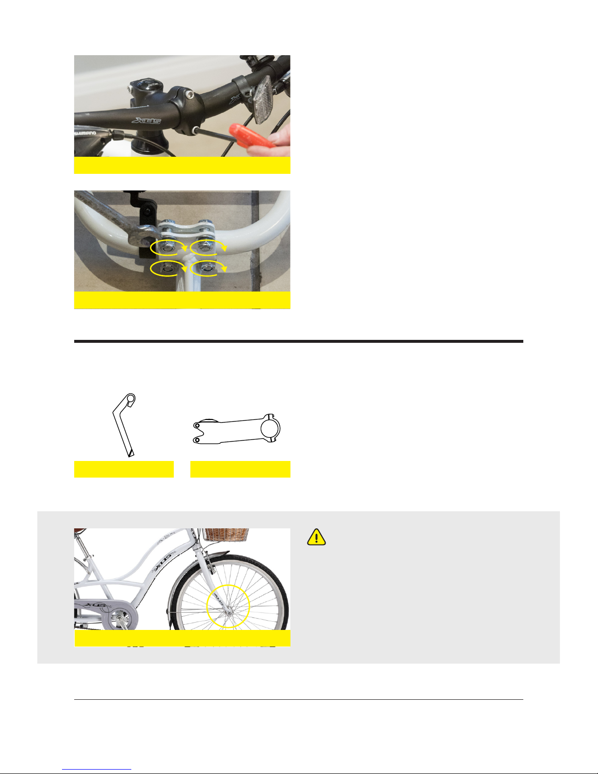
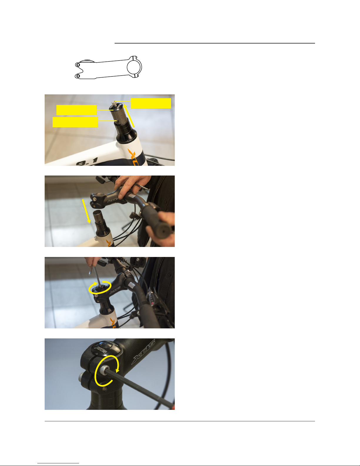
GLOBAL FITNESS & LEISURE BICYCLE User manual

GLOBAL FITNESS & LEISURE BICYCLE ASSEMBLY GUIDE
1
INTRODUCTION
BICYCLE ASSEMBLY INSTRUCTIONS
Congratulations on purchasing your brand new bicycle! Your bicycle comes directly to
you requiring some assembly. This guide has been written to guide you through the
additional steps necessary to complete the assembly of your bike.
These instructions are to be used as a guide only, the images used throughout are for
demonstration purposes only and may not be images of your specific bike.
The following instructions will guide you through:
• Tools Required
• Unpacking the bike
• Assembling the handlebars
• Inserting the handlebar assembly
• Installing the saddle and seatpost
• Installing the front fenders (if applicable)
• Installing the front wheels
• Installing and adjusting the brakes
• Installing the pedals
• Attaching the reflectors and bell
• Attaching the front basket (if applicable)
• Installing training wheels (if applicable)
WARNING: In the interests of safety it is recommended that you have this
bicycle assembled by a skilled bicycle mechanic.

GLOBAL FITNESS & LEISURE BICYCLE ASSEMBLY GUIDE
2
BEFORE YOU START: REQUIRED TOOLS
1. UNPACKING
2. ASSEMBLING THE HANDLEBARS
Remove all the packaging from your bike.
Cut the Zip Ties with scissors or wire
cutters to prevent scratching of the frame
and components.
Inspect the bike and all the included parts
to make sure there are no damaged or
missing parts.
1. Wrench 15mm
2. Wrench 13mm
3. Wrench 12mm
4. Wrench 10mm
5. Philips Head Screwdriver
6. Allen Key 5mm
7. Allen Key 6mm
8. Wirecutters
If not already done, insert the handlebars
in the handle bar stem and tighten the
allen key bolts in the stem using an Allen
Key. The handlebar assembly is now ready
to insert into the bicycle frame.
handlebar
allen key bolt
handlebar stem
1 2 3 4 5 6 7 8

GLOBAL FITNESS & LEISURE BICYCLE ASSEMBLY GUIDE
3
When inserting or adjusting
handlebar assemblies the bicycle forks
must be facing the forward direction.
To check this, the wheel mounting slots
must be in the furthest forward position
so the wheel axle will be in front of the
fork when assembled.
Your bike will come with either a threaded
quill stem, or a threadless stem. Follow
the appropriate instructions below to
insert your handlebar assembly into your
bicycle’s head tube.
3. INserting the handlebar ASSEMBLY
correct alignment
quill stem
alternative handlebar assembly
threadless stem
For handlebar stems with a faceplate,
place handlebar between the stem and
faceplate, then insert and tighten the
allen key bolts with an allen key.
Another alternative is shown to the left
which uses nuts and bolts. In this case,
insert and tighten the nuts and bolts with
a wrench.

GLOBAL FITNESS & LEISURE BICYCLE ASSEMBLY GUIDE
4
Quill stems have a wedge shaped
component at the bottom of the stem that
is inserted in the fork steerer tube.
If present, remove the protective cap from
the handlebar stem, loosen the quill bolt
stem, and insert in the bike steerer tube.
Lower into the stem until the “minimum
insertion” mark is not visible.
QUILL STEMS
stem centre bolt
minimum insertion
mark
WARNING: A quill stem’s Minimum Insertion Mark must not be visible
above the top of the headset. If the stem is extended beyond the Minimum
Insertion Mark, the stem may break or damage the fork’s steerer tube,
which could cause you to lose control.
Ensure the handlebars and forks are
aligned and that the handlebars are facing
forward with the brake levers to the front.
Then tighten the stem centre bolt.
Once the front wheel has been assembled
this step should be re-checked, and
repositioned if needed.

GLOBAL FITNESS & LEISURE BICYCLE ASSEMBLY GUIDE
5
This handlebar assembly clamps around
the fork steerer tube with one or more
pinch bolts.
Ensure the fork is held firmly, or on the
ground as the assemble may fall out
during assembly.
Loosen the top cap of the fork steerer and
remove the top cap and bolt. Do not miss
place these components.
Hold the fork assembly and slide the
handlebar assembly onto the fork tube
and replace the top cap and bolt.
Then tighten the top cap bolt until the
handlebar assembly and fork have no free
play. Do not overtighten.
Now tighten the pinch bolts evenly with
the handlebar assembly facing directly
forward.
Once the front wheel has been
assembled this step should be re-
checked, and repositioned if needed.
THREADLESS STEMS
top cap bolt
fork steerer

GLOBAL FITNESS & LEISURE BICYCLE ASSEMBLY GUIDE
6
Adjustable stems
Some bikes have stems that can be
adjusted to increase or decrease the
angle of the stem to a more desirable
position. Ensure the bolt securing the
angle is securely tightened as failure to do
so may cause loss of steering control.
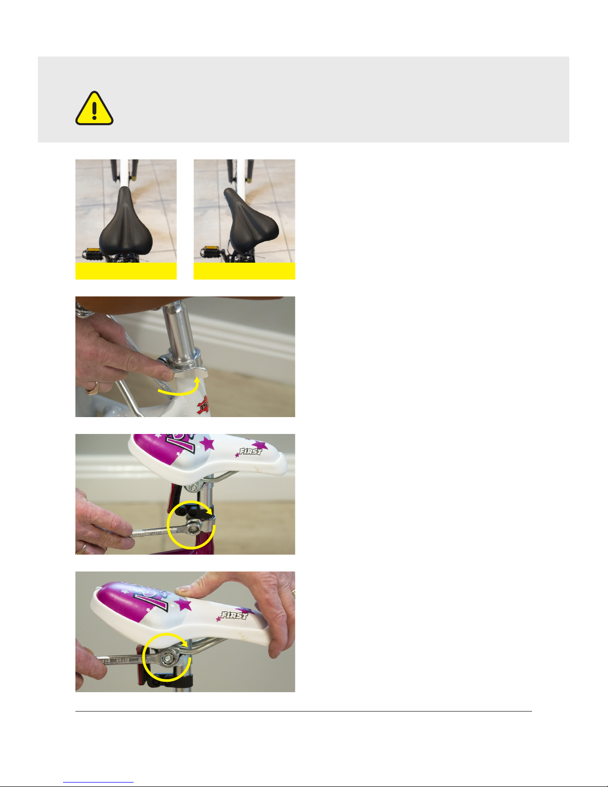
Loosen the seat post clamp. If your bike
has a quick release lever rotate the quick
release clamp until it is fully open.
Quick
release levers operate with an adjusting
nut at one end, and a lever on a cam at
the other end. Always adjust the Quick
release clamp with the lever in the open
position, and by turning the nut (not the
lever).
If your bike has a has a nutted seat post
clamp, use a wrench (or allen key if
appropriate) to loosen the clamp.
Place the seat post into the frame and
slide it down to the desired height,
ensuring the minimum insertion mark
cannot be seen.
4. INSTALLING THE SADDLE & SEAT POST
minimum insertion
mark
nutted seatpost
clamp
quick release lever

GLOBAL FITNESS & LEISURE BICYCLE ASSEMBLY GUIDE
7
Ensure the saddle is aligned with
frame and set at the correct angle for
comfortable cycling.
To align the saddle, stand over the bike
and align the nose of the saddle to run
parallel with the top tube of the frame.
If your bike has a quick release clamp,
tighten the adjusting nut and then close
the quick release lever.
On a nutted seat post clamp, use a
wrench (or allen key if appropriate) to
tighten the clamp.
Ensure that the seat nuts are tightened.
correct incorrect
WARNING: If your seat post is not inserted in the seat tube so that the
Minimum Insertion Mark cannot be seen, the seat post may break, which
could cause you to lose control.

GLOBAL FITNESS & LEISURE BICYCLE ASSEMBLY GUIDE
8
5. INSTALLING THE FRONT FENDERS
Turn the bike over so that it sits on the
saddle and handlebars. Remove the small
plastic rod from between the fork ends.
Position the mudguard between the forks
so that the upper fender mount is behind
the fork, and the fender mounting struts
extend to the fender eyelets.
Align the fender mounting strut holes with
the fender eyelets, place the washers,
then tighten the bolts through with an
allen key.
Then, align the upper fender mount
behind the fork, place the bolt through
from the front of the fork.
If your bike has been supplied with fenders, follow the steps below. If not, skip this
section and move on to installing the front wheel.
mudguard
upper fender
mount
upper fender
mount
fender eyelets
mounting
struts

GLOBAL FITNESS & LEISURE BICYCLE ASSEMBLY GUIDE
9
If your bicycle has tabbed lock washers,
ensure that the locking tabs are correctly
mounted into the holes in the forks.
Your bicycle will come with either a
nutted front wheel or a front wheel with
a quick release mechanism. Follow the
appropriate instructions below to insert
your handlebar assembly into your
bicycle’s head tube.
Thread the nut over the bolt and tighten.
Your front fender has now been installed
and you are ready to install the front
wheel.
quick release nutted
NUTTED FRONT WHEELS
Place the front wheel in the front fork
drop out slots and ensure the wheel fits
correctly. Ensure that the fork dropout sits
in between the lock washer and the cone
nut as shown to the left.
6. INSTALLING THE FRONT WHEEL
If you have not already done so, turn the bike over so that it sits on the saddle and
handlebars. Remove the small plastic rod from between the fork ends.
axle nut cone nut
fork dropout
lock washer

GLOBAL FITNESS & LEISURE BICYCLE ASSEMBLY GUIDE
10
Then fully tighten both nuts and ensure
the wheel sits straight in the forks.
Unscrew the lock nut from the quick
release skewer, remove the outer spring
and slide the skewer through the axle
so the quick release handle is on the left
hand side of the bike.
Re-install the spring and lock nut back on
to the skewer and place the wheel into the
fork slots ensuring the wheel is centred.
Always adjust the Quick release clamp
with the lever in the open position, and by
turning the nut (not the lever).
Close the quick release lever.
QUICK RELEASE FRONT WHEELS
lock nut
skewerspring
forks
lock nut
open
closed
quick release
handle
hub

GLOBAL FITNESS & LEISURE BICYCLE ASSEMBLY GUIDE
11
Unthread the adjusting barrel on the
brake lever a few turns, then align the
slots in the adjusting barrel, the jam nut
and the brake lever.
Insert the cable nipple on the brake cable
into the hole in the lever.
Insert the cable into the slot on the
adjusting barrel and then thread the
adjusting barrel back up to the lever.
You are now ready to install and adjust
your brake calipers.
7. Installing brakes
adjusting barrel
“V” BrakesCaliper Brakes
cable nipple
Your bike will come with one of two
types of brakes: caliper brakes or linear
pull/v brakes. Follow the appropriate
instructions below to install and adjust
your brakes.
Squeeze both brake arms so the brake
pads are against the side wall of the rim.
Ensure the brake cable feeds through the
clamp on the brake arm.
CALIPER BRAKES
BRAKE LEVERS

GLOBAL FITNESS & LEISURE BICYCLE ASSEMBLY GUIDE
12
Linear pull / “v” BRAKES
Then tighten the nut in the clamp to hold
the brakes in position.
Loosen the nut on the brake pad and then
align the brake pad so it runs parallel to
the sidewall of the rim, but allow 1mm
gap so the brake does not rub against the
rim.
Hold each arm so the brake pads can be
adjusted to align with the sidewall of the
rim.
Then hold both arms in position and
insert lower end of the cable lead unit in
to the pivoted metal stirrup.

GLOBAL FITNESS & LEISURE BICYCLE ASSEMBLY GUIDE
13
If more cable length is needed release
the bolt and nut on the end of the brake
arm so that more cable is available. If
released, retighten the bolt and nut to
hold cable in the notch on the lever arm.
Place the rubber protector over the end of
the brake cable.
Loosen the nut on the brake pad and then
align the brake pad so it runs parallel to
the sidewall of the rim, but allow 1mm
gap so the brake does not rub against the
rim.
The pedals are marked as either Right or
Left, R or L. The pedals will be marked on
the end of the pedal spindle and possibly
also by a decal on the pedal body.
The right hand side of the bike is the
chainwheel side of the bike.
8. installing the PEDALS
WARNING: Incorrect attachment of the pedal into the crank arm can strip
the thread from the pedal spindle, or the threads in the crank arm, and
cause irreparable damage.
right pedal left pedal

GLOBAL FITNESS & LEISURE BICYCLE ASSEMBLY GUIDE
14
The reflectors must be positioned and
clamped into place. Using a screwdriver,
loosen the mounting clamp. Position the
reflector ensuring it is facing outwards
and retighten the clamp. The white
reflector is for the front of the bicycle.
Note: The right hand side of the bike is
the chainwheel side of the bike. Insert the
Right Pedal into the Right pedal arm and
turn the thread clockwise. Fully tighten
with a 15mm narrow open ended wrench.
Insert the Left Pedal into the Left pedal
arm and turn the thread anti-clockwise.
Fully tighten with a 15mm open ended
wrench.
9. Attaching the REFLECTORS & Bell
WARNING: Reflectors are not a substitute for required lights. Riding at
dawn, dusk, night or at other times of poor visibility without an adequate
bicycle lighting system and without reflectors is dangerous and may result
in serious injury or death.
front reflector
right pedal
left pedal

GLOBAL FITNESS & LEISURE BICYCLE ASSEMBLY GUIDE
15
Position and mount the red reflector on
the seatpost at the rear of the bicycle.
Place the bell into position so that it can
be easily used and then tighten the clamp.
If you have been supplied with a steel
bracket for the lower basket mount
attach this to the front of the fork using a
screwdriver.
If you have been supplied with a strutted
lower basket mount as on a ladies’ alloy
retro, attach the struts to the front eyelet
on the fork dropouts.
Follow these instructions if you have been supplied a front basket with your bicycle.
10. Attaching the FRONT BASKET
rear reflector
lower basket mount
bell

GLOBAL FITNESS & LEISURE BICYCLE ASSEMBLY GUIDE
16
Follow these instructions if you have been supplied training wheels with your bicycle.
Loosen and remove the nut at the rear
dropout of the bicycle.
Bolt the basket to the lower basket mount
using a screwdriver.
11. Installing Training WHeels
Bolt the basket to the upper basket
mount located above the headtube of the
bicycle.
upper basket mount
For steel retro bicycles the lower basket
mount struts will attach to the front wheel
hub at the fork dropout.

GLOBAL FITNESS & LEISURE BICYCLE ASSEMBLY GUIDE
17
Place the training wheel over the smaller
steel bracket.
Then, place the large steel bracket over
the training wheel.
Finally, thread the nut back onto the bolt
over the training wheel assembly.
Then, tighten the bolt and repeat for the
opposite side of the bicycle.
Place the small steel bracket over the
bolt.

GLOBAL FITNESS & LEISURE BICYCLE ASSEMBLY GUIDE
18
12. INFLATING Your TYRES
Before riding your bicycle, you must
inflate your tyre up to the correct
pressure. There are two kinds of
bicycle tube valves in common use: the
Schraeder (Car) Valve and the Presta
Valve (also known as a French Valve).
Identify which valve you have and follow
the appropriate instructions below to
inflate your tyres.
A Presta valve has a narrower diameter and is only found on
bicycle tyres. To inflate a Presta valve using a Presta headed
bicycle pump:
• Remove the valve cap
• Unscrew the valve stem lock nut
• Push down on the valve stem to free it up
• Push the pump head on to the valve head and inflate to the
PSI or KPA value written on the sidewall of your tyre. (Refer
to page 43 of your bicycle owner’s manual for a KPI to PSI
conversion table.)
• The Schraeder valve is like the valve on a car tyre. To Inflate a
Schrader valve tube:
• Remove the valve cap and push the pump head on to the valve
stem.
• Inflate to the PSI or KPA value written on the sidewall of your
tyre. (Refer to page 43 of your bicycle owner’s manual for a
KPI to PSI conversion table.)
Presta Valve
SCHRAEDER Valve
presta valve schraeder valve
Table of contents